Vision-based SLAM#
Pre-requisites and initial checks#
In order to navigate with ARI the following components are needed:
Tablet/screen
Computer
ROS noetic or PAL gallium installed
Robot
Joystick (if available)
rviz
Before continuing with the instructions of this section make sure that the robot
computer is able to resolve the development computer hostname. Otherwise, some
commands will not work with the real robot due to communication failures
between the robot’s computer and the development computer. We will assume that
the development computer’s IP is 10.68.0.128, which will be set in the
ROS_IP environment variable. The user will have to adapt the examples below
to set the right IP address.
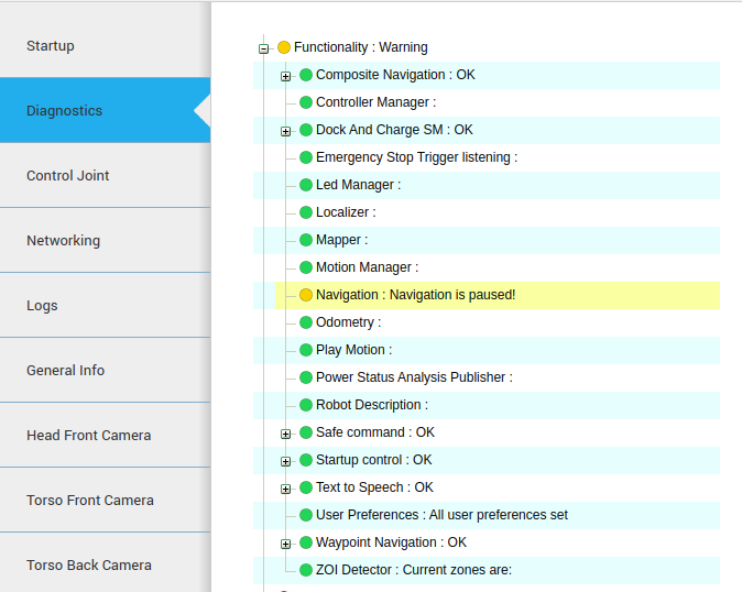
Note that when the robot is charging (either using the docking station or a cable), the navigation functionality is paused for safety. The status of the functionality can be checked in the WebCommander diagnostics tab, see figure below.
Note
Alternatively, the status can be checked in /pause_navigation topic, which reports a boolean specifying whether the functionality is paused.
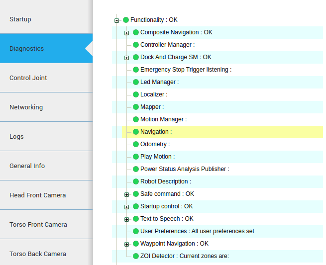
Make also sure that no errors are visible in the diagnostics tab (no red indications) and that all are green.
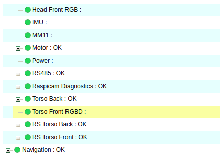
At the same time, make sure that the torso front camera is publishing correctly, as it is the camera that will be used for navigation. For this you may check that in the Hardware section of the Diagnostics tab the RS Torso Front appears green.
Starting the navigation system#
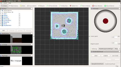
In order to visualise the mapping and localization pipeline using rviz,
the ROS visualisation interface, from your development computer, the following
command should be run in order to launch PAL’s rviz Map Editor with a
specific file for navigation, provided with ari_2dnav.
export ROS_MASTER_URI=http://ari-0c:11311
export ROS_IP=10.68.0.128
rosrun rviz rviz -d `rospack find ari_2dnav`/config/rviz/navigation.rviz
In order to ensure that rviz works properly, make sure that the robot computer
is able to resolve the development computer hostname.
When the robot boots, the navigation pipeline starts automatically. Furthermore, the localization mode, using the last map, will be active.
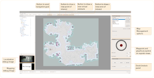
Through here it is possible to:
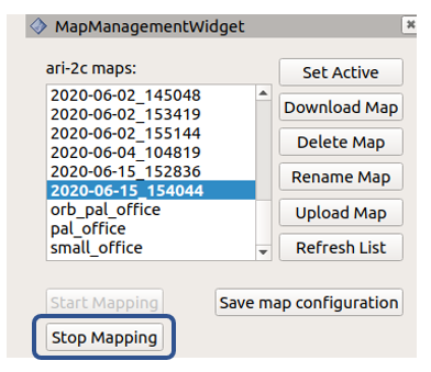
Start and stop mapping, by pressing the corresponding buttons in the MapManagementWidget, as well as perform other map operations.
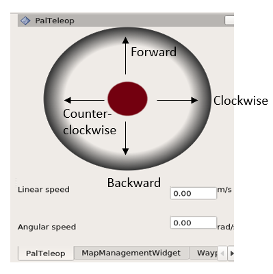
Move the robot around using the graphical joystick, on the PalTeleop tab, by guiding the red circle forward, backwards, or to the lateral sides in order to turn the robot clockwise/anti-clockwise
Generate POIs and execute a trajectory through them using the Waypoint Group tab
Dock/undock the robot in order to charge it, using the DockUndock panel
The upper horizontal bar contains a list of buttons to send:
navigation goal
create a POI
Virtual Obstacles
Zones of Interests
The left bar enables the user to visualize different components (e.g. mapping, localization, planning, the robot model), including the image outputs such as the keypoints detected through localization.
Creating a map#
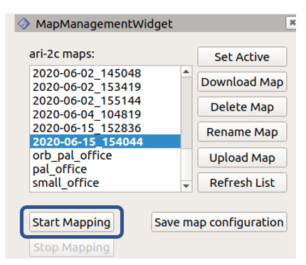
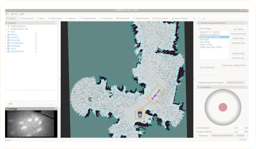
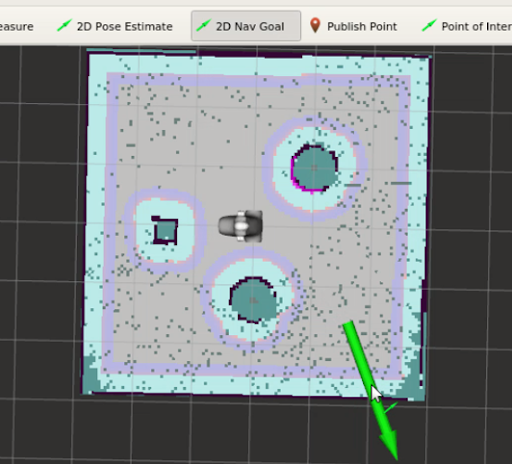
In order to create a new map focus on the right panel of rviz, where the
Start/Stop Mapping buttons and the PalTeleop joystick
are displayed. Press the button Start Mapping to begin the mapping
process.
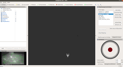
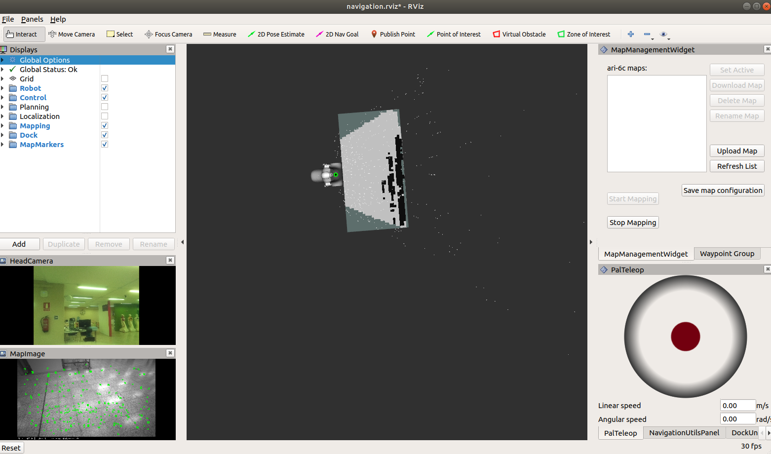
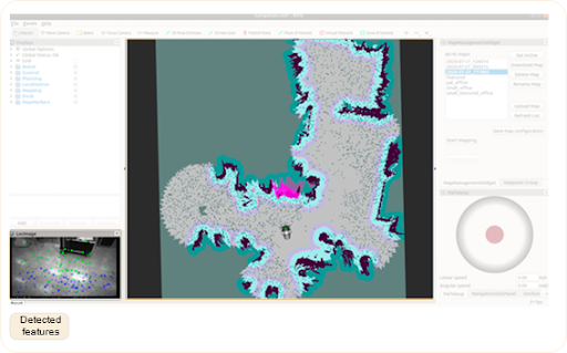
The rviz interface will change to that of the figure below.
The robot base can be then tele-operated using the key_teleop node
or the graphical joystick of rviz by dragging and keeping the red button in
the desired orientation, to move the robot forward or backwards, or to rotate it
clockwise/counter-clockwise.
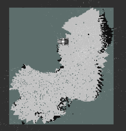
You will see the occupancy grid map updating as the robot moves.
Please make sure you can drive the robot safely before attempting to increase the speeds.
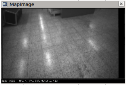
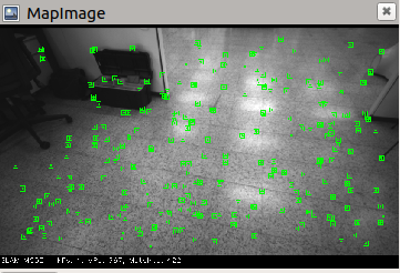
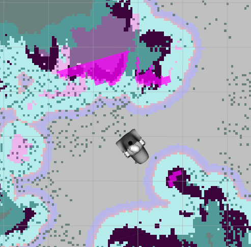
As you move the robot and it starts mapping, in order to make sure that the map is being done correctly, make sure that:
Green points are being detected in the
MapImageinterface. These are features or keypoints that the Visual SLAM algorithm detects through the torso RGB-D camera.
As the joystick is moved the robot should move accordingly in the map as its estimated pose is updated. It also serves to hint where it should go to continue mapping
Note
To improve mapping process, it is recommended that you:
Move the robot slowly
Avoid sharp turns
Drive in circles in the same direction, by returning to a previous location so that the robot can recognise an already visited area to optimize the map.
Try to drive along walls and have objects in sight
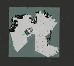
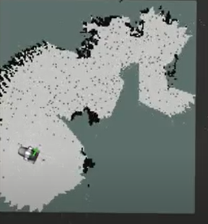
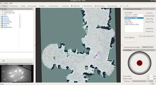
If at a given time key points disappear from the image, attempt to slow down the speed or return to the area where the robot was able to detect them previously. The figures below show a sample mapping process where the occupancy grid map is extended progressively.
Then it is time to Stop Mapping. This will create a new map on the robot with a name consisting of a time-stamp that can be used for localization and navigation. Bear in mind it may take a while to process and to store the map. For further details regarding where the mapping is stored, refer to Managing maps.
At the same time, the robot will start using it for localization and path planning, once the Start Mapping option is activated again. If you would like to have more information on how to manage maps refer to Managing maps (including console-based options).
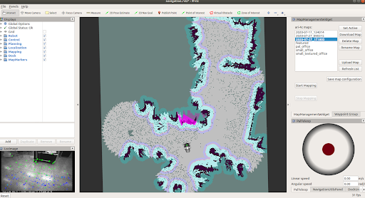
Localization#
Once the Start Mapping option becomes available again the new map will be loaded and the robot will be localizing in it.
You will see the occupancy grid map, as well as the localization debug image, that will output the keypoints detected through Visual SLAM and match them to the map built previously.
Note that in order to safely send navigation goals it is important to ensure the robot is well localised in the map, as otherwise the robot will not be able to reach the goal.
Because of this, before proceeding to path planning, ensure that the robot is well localized in the map:
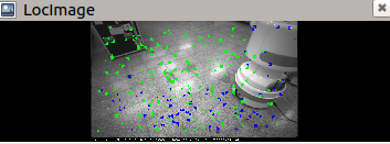
The
LocImagedebug image on the left, which visualizes the output of the torso RGB-D camera, has some green key points in it, indicating that the localization system is recognising and matching features corresponding to the map built previously.
Costmaps are aligned, that is, that regions where obstacles should be are indicated properly.
The /move_base node maintains two costmaps, one for the
global planner and one for a local planner. They are visible in rviz through
the Planning section of the left panel:
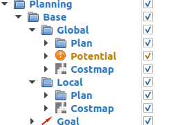
Global costmap: digital representation used by the global planner in order to compute paths to navigate from one point of the map to another without getting too close to the static obstacles registered during mapping. More details can be found here: http://wiki.ros.org/costmap_2d
Local costmap: similar to the global costmap, but it is smaller and moves with the robot, it is used to take into account new obstacles that were not present in the original map. It is used by the teb_local_planner node to avoid obstacles, both static and dynamic, while trying to follow the global path computed by the global planner. More details can be found here: http://wiki.ros.org/costmap_2d.
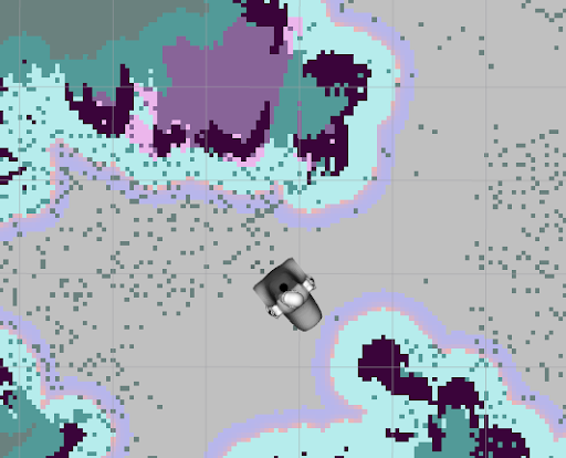
As the robot is navigating, the costmaps should be updated accordingly, indicating the walls and obstacles at the expected locations.
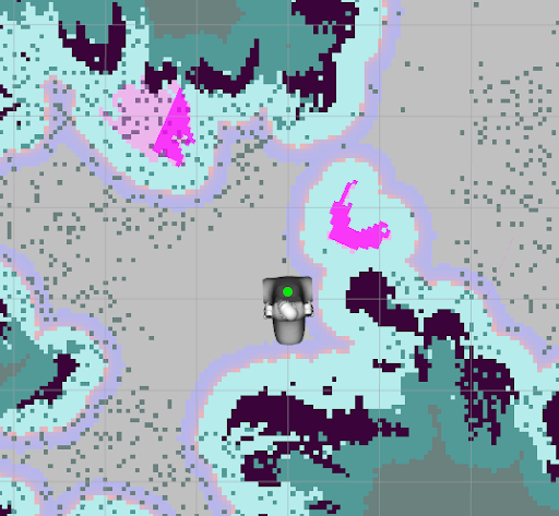
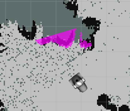
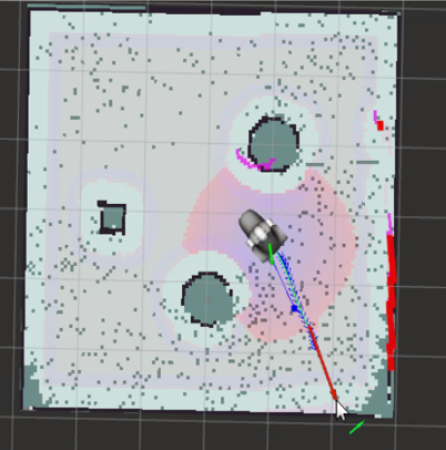
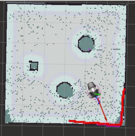
The figure below shows an example of the robot getting lost, as it is not detecting any keypoints through the image on the left bar and the robot is not in the right place in the map.
If no keypoints are detected and the costmaps do not appear aligned, the robot will rely on wheel odometry until it returns to a known area. Some reasons why this could happen are:
robot has moved to an area that is outside the generated map,
new objects have been added to the scene after producing the initial map
If the environment has not changed and the robot is within the mapped area, but the robot gets lost, attempt to return the robot towards the initial position or an area where it was previously localised.
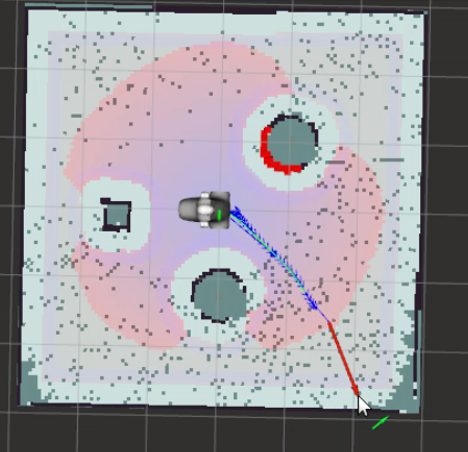
Localization and autonomous navigation#
Executing the following on a terminal will start the simulation in localization and path planning mode.
roslaunch ari_2dnav_gazebo ari_navigation.launch
A Gazebo window will open, with the robot in a small enclosed environment, and will load the latest map created, indicating as well the localization debug image with detected keypoint and the localized robot model in the map.
Ensure that the robot is well localized before sending navigation goals. The figure below shows a sequence:
Points of interests, zones of interest, virtual obstacles#
Like with laser-based mapping, you can define points of interest, virtual obstacle and zones of interest.
Learn how to do that here: Points of interests, zones of interest, virtual obstacles.