Laser-based SLAM and path planning on the robot with RViz#
Pre-requisites#
Before you start mapping, make sure the robot is undocked. Otherwise the robot will not move for security purposes. Follow the undocking section to do so.
Make sure that the robot computer is able to resolve the development computer hostname. Set the right
ROS_MASTER_URIandROS_IPenvironment variables in the development computer.
Creating a new map with Laser Scanner#
Step 1. Start the mapping process. Open rviz:
rosrun rviz rviz -d `rospack find ari_2dnav`/config/rviz/navigation.rviz
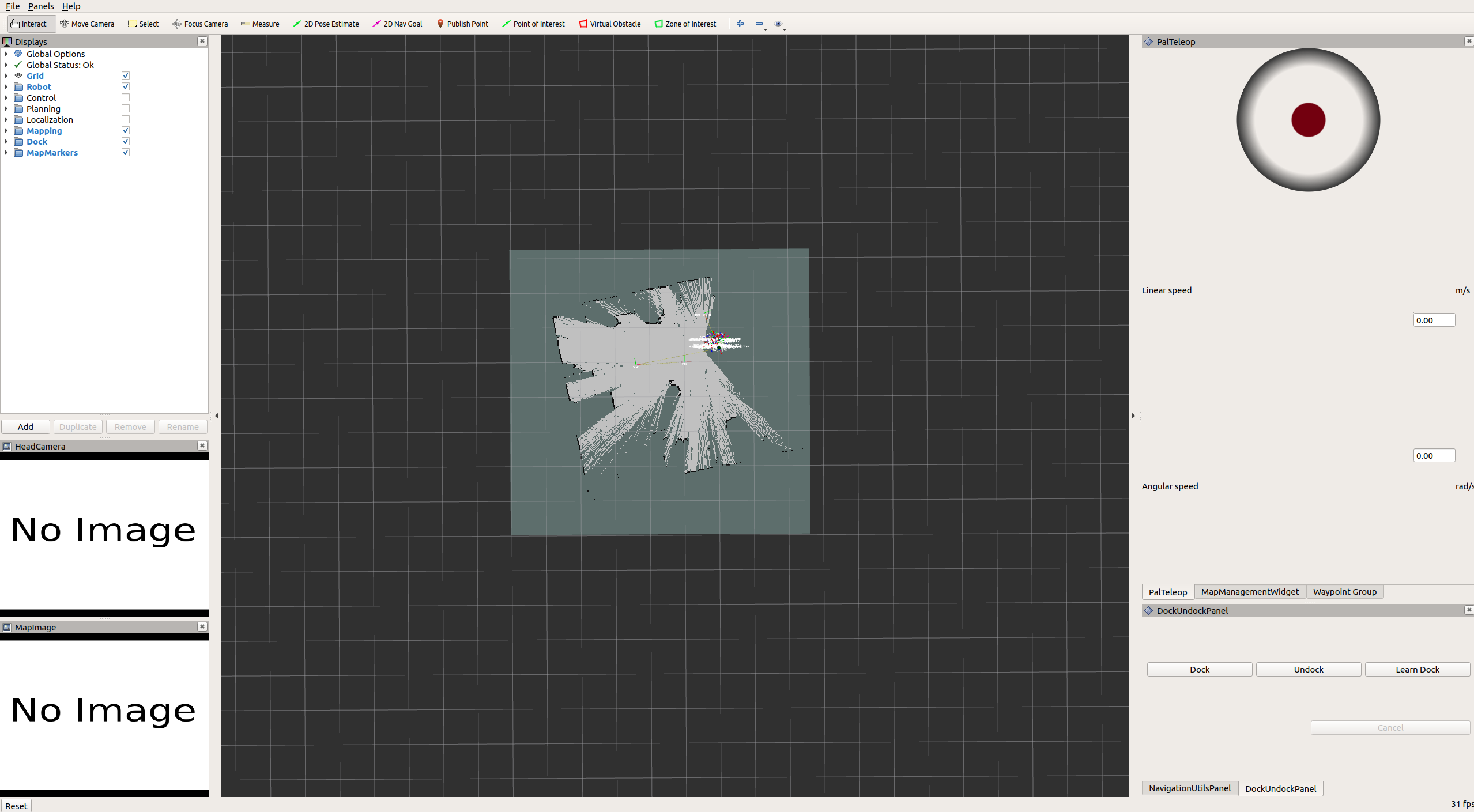
You’ll see the following rviz interface:
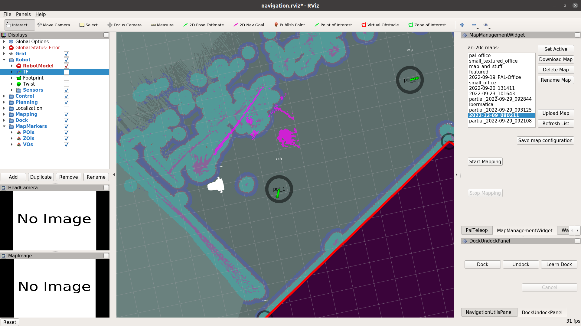
In order to create a new map focus on the right panel of rviz, where the
PalTeleop and MapManagementWidget tabs are located. Go
to MapManagementWidget tab and press the Start Mapping button
to begin the mapping process.
The rviz interface will change to that of the figure below:
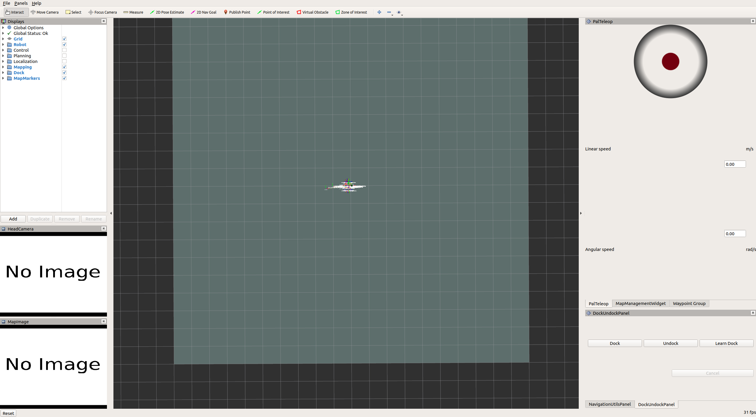
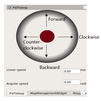
Step 2. Map the area The robot base can be then tele-operated using the
key_teleop package or the graphical joystick of rviz by dragging and keeping the
red button in the desired orientation, to move the robot forward or backwards,
or to rotate it clockwise/counter-clockwise.
You will see the occupancy grid map updating as the robot moves.
Please make sure you can drive the robot safely before attempting to increase the speeds.
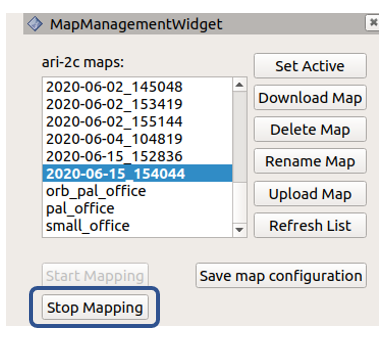
Step 3. Stop mapping. Once all the desired area has been covered, press the
Stop Mapping button in the MapManagementWidget. This will create
a new map on the robot with a name consisting of a time-stamp that can be used
for localization and navigation. Bear in mind it may take a while to process and
to store the map. Press the Refresh List if you do not see your
current map.
Note
To improve the mapping process, it is recommended that you:
Move the robot slowly
Avoid sharp turns
Drive in circles in the same direction, by returning to a previous location so that the robot can recognise an already visited area to optimize the map.
Try to drive along walls and have objects in sight
For further details in where the mapping is stored refer Managing maps.
Localization with Laser Scanner#
Once the mapping process has been completed, the new map will be loaded and the robot will be localizing in it. Note that the correct localization of the robot in the map is a main requirement in order to safely perform the navigation of the robot in the map. This allows the user to specify a goal or a set of goals in the maps and the robot will plan a trajectory to navigate safely through them while performing obstacle avoidance. Therefore, before proceeding to path planning, ensure that the robot is well localized in the map.
Checking the current localization status of the robot#
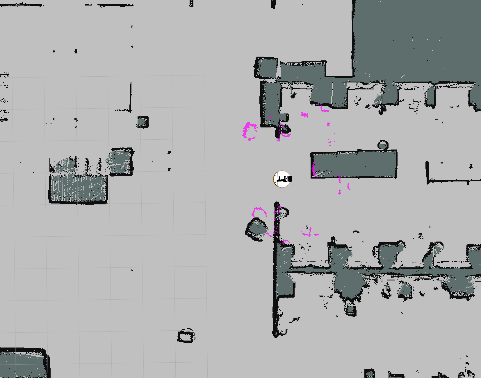
Open rviz (if you haven’t done that already). You should now see the
occupancy grid map, as well as the output of the Laser Scanner as a set of
adjacent points that overlaps the created map:
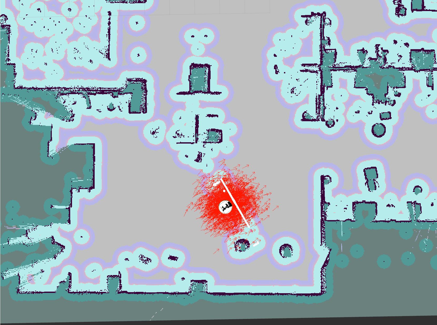
After moving a bit the robot in the map, it will be able to locate in the map with more accuracy. The red particles cloud will become smaller and smaller as the robot becomes more confident about its position in the map
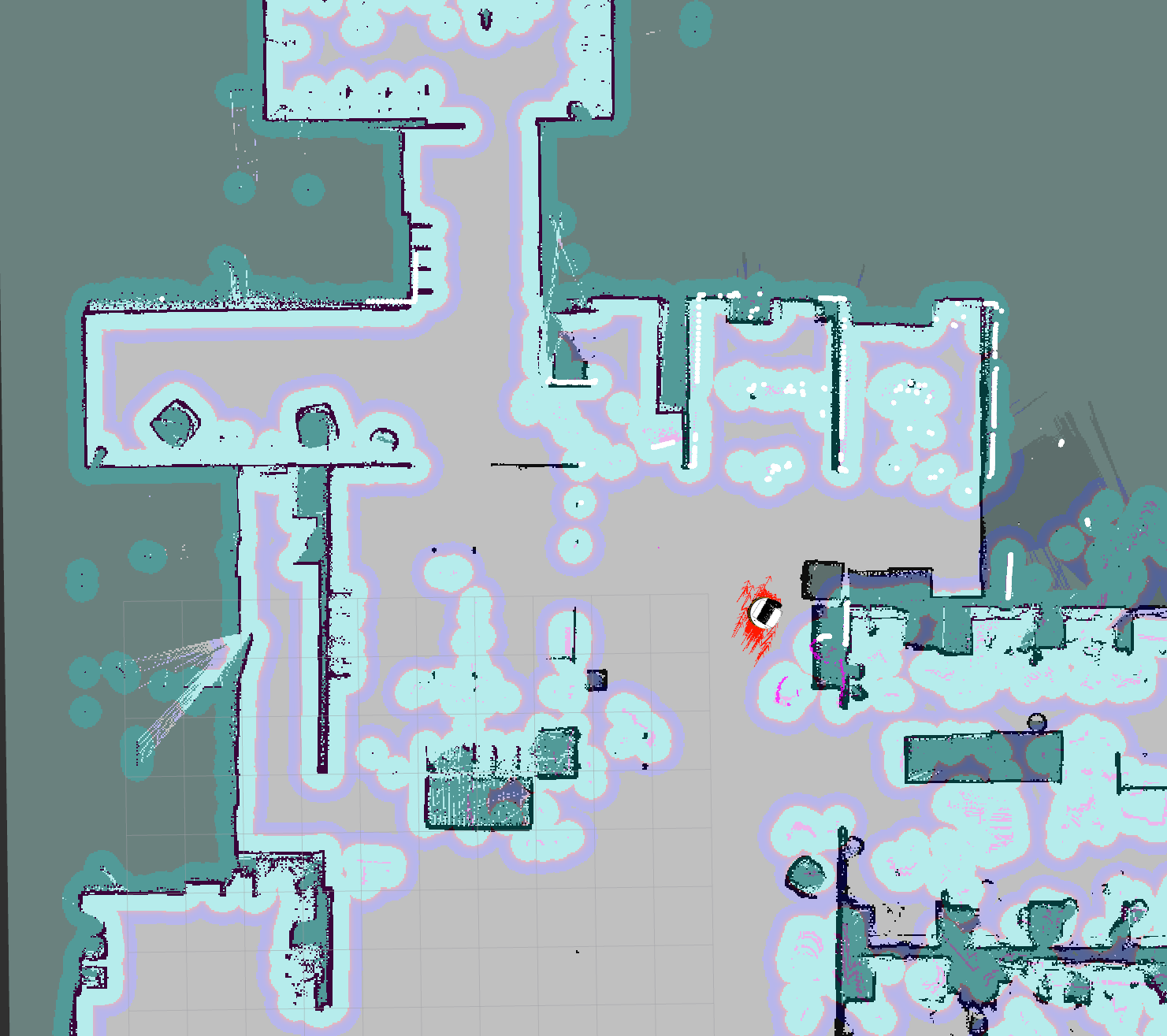
You can see that the robot is correctly localized in the map by observing the laser scan points (in white) and comparing them to the fixed obstacles in the map (in black). Their correspondance means that the robot is correctly localized in the map and can safely navigate in it.
In order for the robot to navigate safely in the map, it maintains two costmaps:
one for the global planner and one for a local planner. They are visible in
rviz through the Planning section on the left panel:
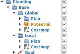
Global costmap: digital representation used by the global planner in order to compute paths to navigate from one point of the map to another without getting too close to the static obstacles registered during mapping. More details can be found here: http://wiki.ros.org/costmap_2d
Local costmap: similar to the global costmap, but it is smaller and moves with the robot. It is used to take into account new obstacles that were not present in the original map. It is used by the
teb_local_plannerto avoid obstacles, both static and dynamic, while trying to follow the global path computed by the global planner. More details can be found here: http://wiki.ros.org/costmap_2d.
As the robot navigates, the costmaps should be updated accordingly, indicating the walls and obstacles at the expected locations.
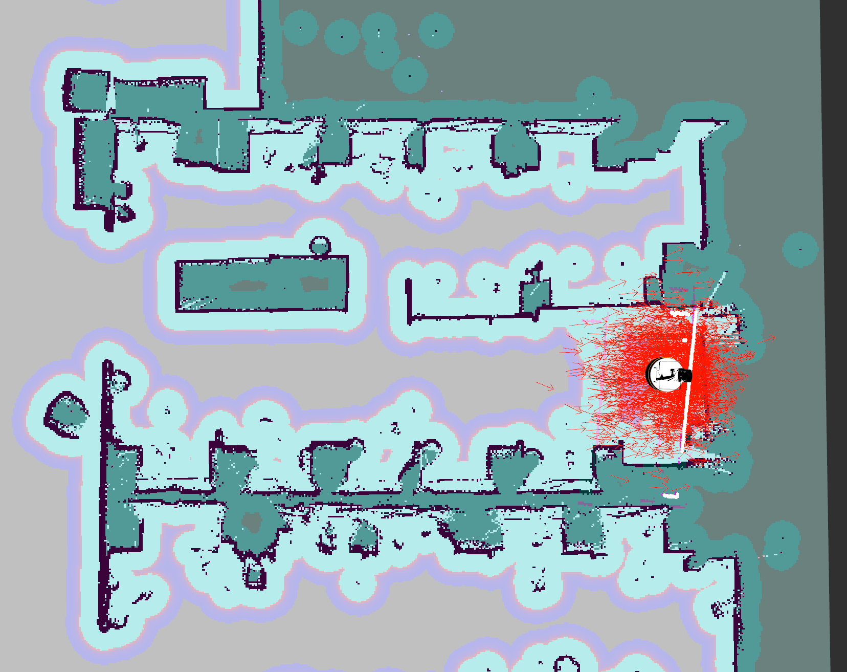
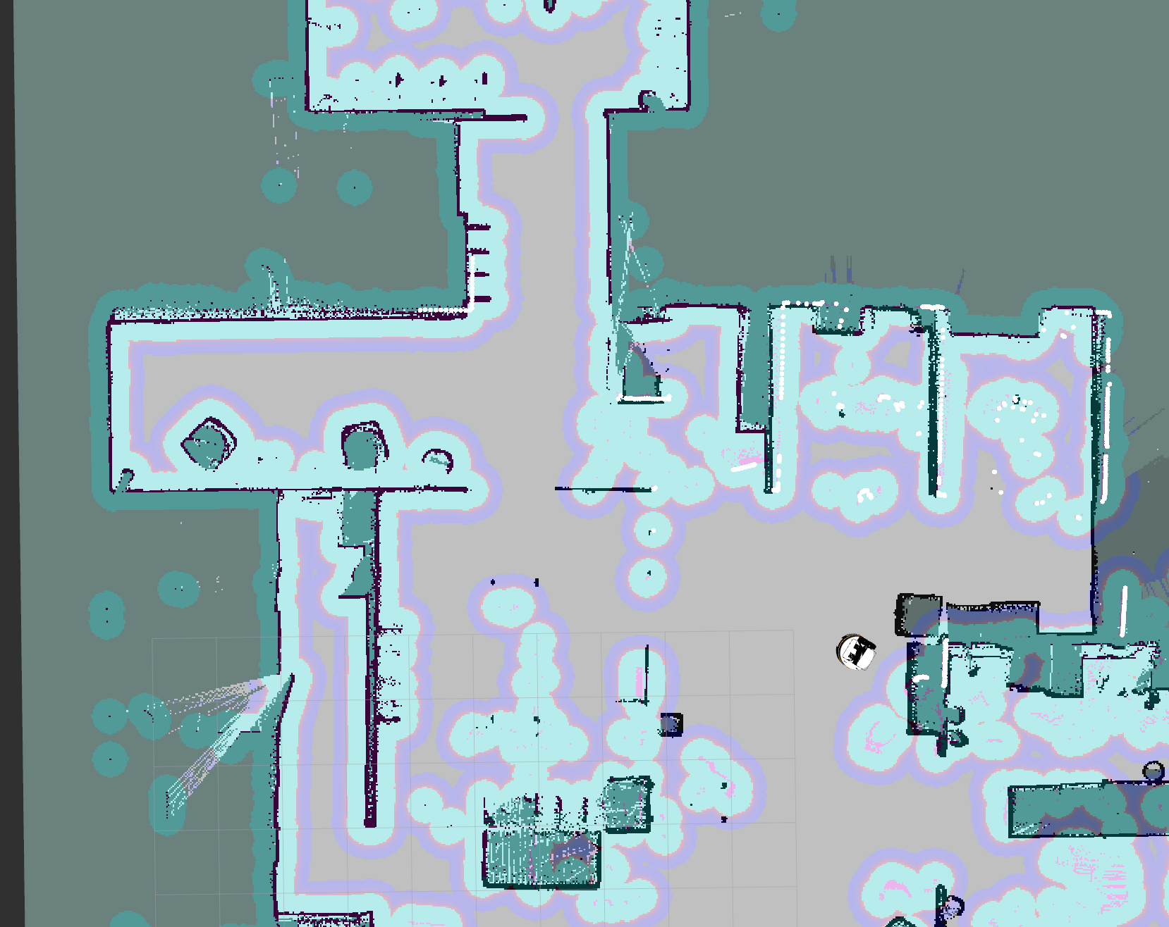
The figure below shows an example of the robot getting lost, since there is no correspondance between the points coming from the Laser Scanner and the fixed obstacles of the recorded map.
Some reasons why this could happen are:
robot has moved to an area that is outside the generated map
new objects have been added to the scene after producing the initial map
the robot has encountered is experiencing a severe and prolonged slippage
Localizing the robot in the map#
To help localize your robot in the map, you can:
Manually provide its current pose:
Step 1. Press the 2D Pose Estimate button in the top rviz menu.

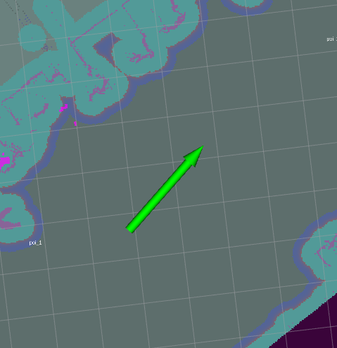
Step 2. Manually select the pose and the orientation of the robot in the map. To do so, press the left button on your mouse at the desired location in the map (a green arrow will appear). Without releasing the mouse button, modify the robot orientation by moving the mouse (the green arrow will rotate).
2. If the environment has not changed and the robot is within the mapped area, but the robot is lost, try to return the robot towards the initial position or an area where it was previously localised.
Points of interests, zones of interest, virtual obstacles#
This section covers additional functionalities of the rviz panel that allow
the user to define and execute a trajectory along points of interests, set-up
zones of interests and edit the map to include virtual obstacles.
Defining Points of Interest#
A Point of Interest (POI) is a pose in the map defined by a set of coordinates and orientation. Once a POI is defined and stored in the map metadata the robot can be sent to the POI using the action_go_to_poi action interface.
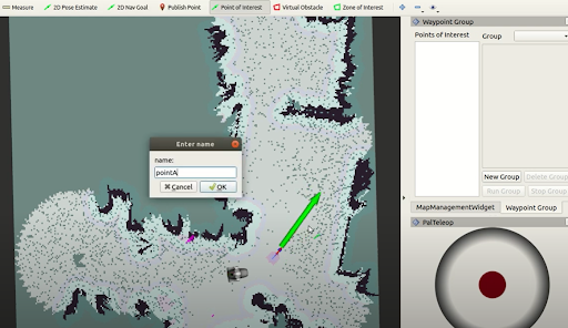
To create a new POI, press the button Point of Interest on the top bar of the Map Editor. Then move the mouse to the desired map location, press the mouse’s left button and drag the mouse to define the orientation of the POI. Release the mouse’s button to create the POI. Afterwards, a dialog requesting the name of the POI will show up as shown in the figure below. After accepting it the POI will be created.
In order to get these meta-data permanently stored press Save map configuration.
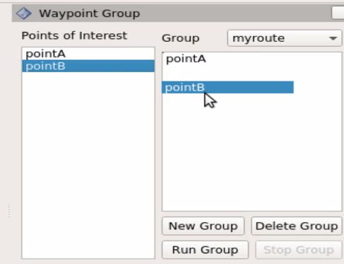
After creating POIs, you can define groups of POIs. By running a group of POIs, the robot will visit in sequence all the POIs in the group.
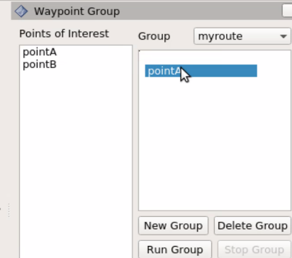
Use the panel Waypoint Group to create groups of POIs. The list on the left
of the panel shows all the POIs created. First press New Group to
define a new group of POIs. A dialog requesting the name of the group will
appear, the figure below. In order to add POIs first select the POI on the left
list and drag-and-drop it to the panel of its right. The same POI can be set
multiple times. When the group contains all the desired POIs press
Save map configuration.
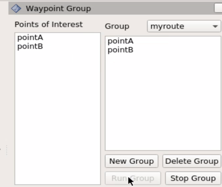
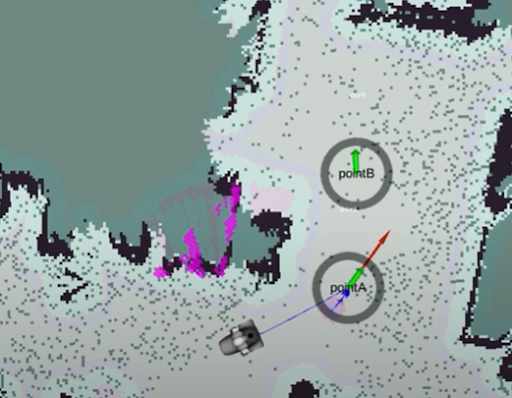
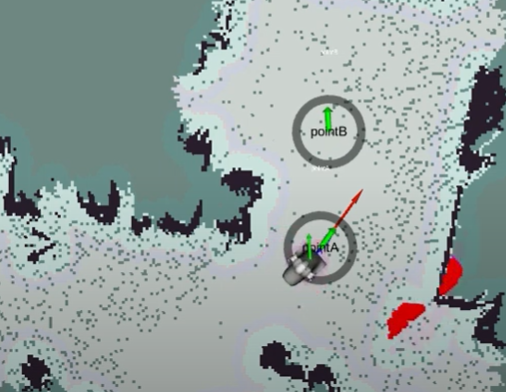
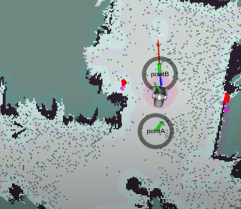
The robot will visit in sequence all the POIs in a group by selecting it in the dropdown list named Group and then pressing the Run Group. The task can be cancelled at any time by pressing Stop group. The figure below shows the robot running a group of 2 POIs while avoiding virtual obstacles (VOs– we will go through these next). In order to run a group of POIs the action interface action_pal_waypoint-navigate is available.
Defining Zones of Interest#
Zones of Interest (ZOI) provide a simple way to have topological localization, i.e. Obtain the name of the zone of the map where the robot is located. A ZOI can be defined by pressing the Zone of Interest button on the top bar of the Map Editor.
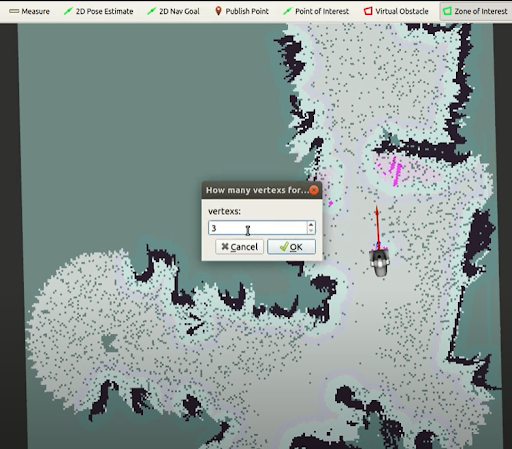
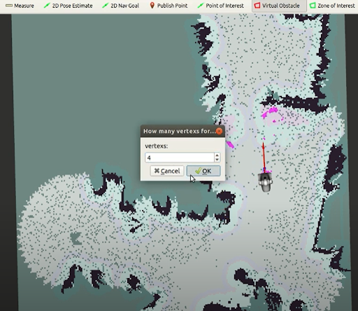
By clicking on a map point the user specifies the central position of the ZOI. Afterwards, a dialog requesting the name of the zone and then another requesting how many points will be used to define the zone will appear (see the figures below).
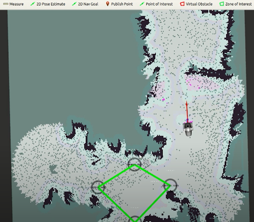
A green polygon with the selected number of vertices will appear on the selection map point. You can then drag the vertices with the mouse to define the final placement of the Zone of Interest. Note that in order to move a vertex of the zone the mouse icon must be placed on top of the blue circle, the color of the circle will vary slightly, before clicking on it and dragging it.

Defining Virtual Obstacles#
Virtual obstacles (VO) are of key importance to prevent some dangerous situations during navigation, such as falling downstairs or colliding with obstacles not clearly visible to the robot’s sensors, or to label forbidden areas where the robot is not allowed to enter.
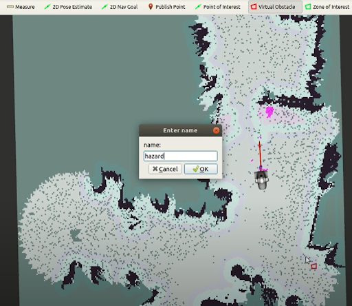
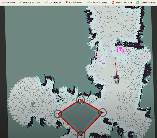
The VOs are created the same way as the ZOIs by pressing the Virtual Obstacle button on the top bar of the Map Editor. VOs are represented with red polygons (see the figures below). In order to store the meta-data defining the VOs, press Save map configuration.
Modifying map meta-data#
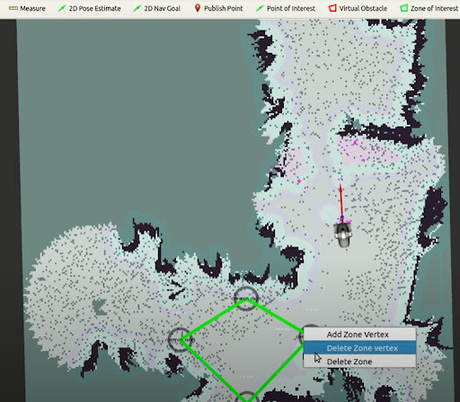
The POIs, ZOIs and VOs can be modified at any time or removed by placing the mouse icon on top of their blue circle and clicking on the right button. A popup menu will appear providing different options:
removing a POI
adding new vertices to ZOIs and VOs
removing a vertex or removing the whole ZOI or VO.
After any modification of the POIs, ZOIs or VOs remember to press Save map configuration to store the changes permanently in the map.