Mobile base#
TIAGo’s mobile base is provided with a differential drive mechanism and contains an onboard computer, batteries, power connector, laser-range finder, three rear sonars, a user panel, a service panel and two WiFi networks to ensure wireless connectivity. Furthermore, the version of TIAGo with a docking station has a charging plate on the front
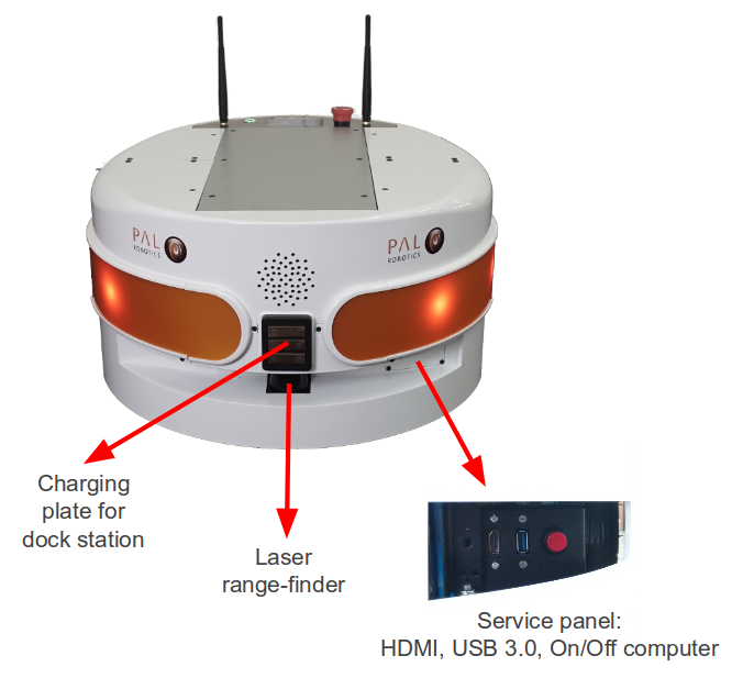
Figure: Mobile base front view#
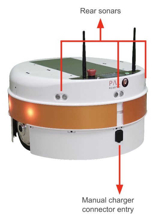
Figure: Mobile base rear view#
Onboard computer#
The specifications of TIAGo ’s onboard computer depends on the configuration options you have ordered. The different possibilities are shown in table below:
Component |
Description |
|---|---|
CPU |
Intel i5 / i7 |
RAM |
8 / 16 GB |
Hard disk |
250 / 500 GB SSD |
Wi-Fi |
802.11 a/b/g/n/ac |
Bluetooth |
Smart 4.0 Smart Ready |
Battery#
The specifications of the battery supplied with TIAGo are shown in table:
Type |
Li-Ion |
|---|---|
V_nominal |
36.0 V |
V_max |
42.0 V |
V_cutoff |
30.0 V |
Nominal capacity |
20 Ah |
Nominal energy |
720 Wh |
Max. continuous discharge current |
20 A |
Pulse discharge current |
60 A |
Max. charging current |
15 A |
Charging method |
CC/CV |
Weight |
7.5 kg |
TIAGo can be equipped with two batteries. In this case, the total Nominal capacity is 1440 Wh.
Power connector#
TIAGo must be charged only with suplied charger. To insert the charger connector, open the lid located on the rear part.
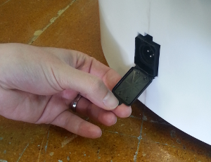
Figure: Charging connector entry#
Connection Insert charging connector with metal lock facing up, push it until you hear a ’click’.
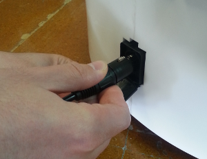
Figure: Charger connector insertion procedure#
Disconnection Once charge is completed, connector can be removed. In order to do so, press metal lock and pull firmly the connector (see the figure below).
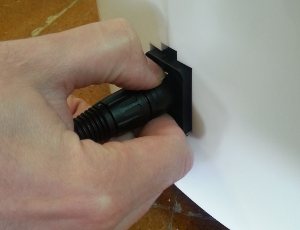
Figure: Charger connector removal procedure#
Laser range-finder#
The specifications of the laser on the front part of the mobile base depend on the configuration options you have ordered. The lasers supported are shown in table:
Manufacturer |
Hokuyo |
|---|---|
Model |
URG-04LX-UG01 |
Range |
0.02 - 5.6 m |
Frequency |
10 Hz |
Field of view |
180 degrees |
Step angle: |
0.36 degrees |
Manufacturer |
SICK |
|---|---|
Model |
TIM561-2050101 |
Range |
0.05 - 10 m |
Frequency |
15 Hz |
Field of view |
180 degrees |
Step angle: |
0.33 degrees |
Manufacturer |
SICK |
|---|---|
Model |
TIM571-2050101 |
Range |
0.05 - 25 m |
Frequency |
15 Hz |
Field of view |
180 degrees |
Step angle: |
0.33 degrees |
Sonars#
The rear part of the mobile base has three ultrasound sensors, here referred to as sonars. One is centered and the other two are placed at 30º on the left and right. See table for the sonar’s specifications
Manufacturer |
Devantech |
|---|---|
Model |
SFR05 |
Frequency |
40 kHz |
Measure distance |
0.03 - 1 m |
IMU#
The Inertial Measurement Unit is mounted at the center of the mobile base and may be used to monitor inertial forces and attitude. The specifications are presented in the table:
Manufacturer |
InvenSense |
|---|---|
Model |
MPU-6050 |
Gyroscope |
3-axis |
Accelerometer |
3-axis |
User panel#
The user panel is on the top, rear part of TIAGo mobile base. It provides the buttons to power up and shutdown the robot, and a screen to give visual feedback on the robot’s status. All the specific elements of the user panel are shown in the figure below and the description of each element is presented in teh table:
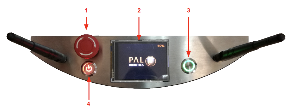
Figure: User Panel#
Number |
Name / Short description |
|---|---|
1 |
Emergency stop |
2 |
Information display |
3 |
On / Off button |
4 |
Electric switch |
Electric switch The electric switch is the main power control switch. Before turning TIAGo ON make sure first that this switch is ON, i.e. its red light indicator is ON. On the other hand, when TIAGo is not going to be used for a long period, please press the switch so that its red light indicator turns OFF. Note that this switch should not be turned OFF before using the On/Off button to turn OFF the onboard computer of the robot. Turning OFF this switch will cut instantaneously the power supply to all the robot components, including the onboard computer. Do not use this switch as emergency stop. For the emergency stop please refer to the next section.
Emergency stop When pushed, motors are stopped and disconnected. Green indicator will blink fast in order to notify the emergency state.
To start the normal behaviour again, a two step validation must be executed: emergency button must be released rotating clockwise, and then On/On button must be pressed for 1 second. The green light will change to fixed state.
Information display 320x240 Color TFT display that shows battery level on the top-right corner.
On / Off button Standby control button. It is a push button with a green light to indicate the current system status.
Light |
State |
Name / Short description |
|---|---|---|
Off |
Fixed |
Standby |
On |
Fixed |
Running |
On |
Slow-Blink |
System in process of shutdown |
On |
Fast-Blink |
Emergency state |
After main power is connected, i.e. electric switch is ON (see Figure: User Panel), user must press this button during 1 second in order to start the TIAGo.
To set again the system in standby mode when is running, press again the button. The green light will blink slowly during shut down procedure and light-off when standby mode reached.
Service panel#
It is possible to access the service panel by removing the cover behind the laser (see Figure: Service panel).
This service panel gives access to video, usb and on/off button of the robot’s computer. It can be used for reinstallation or debug propouses.
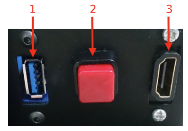
Figure: Service panel#
Number |
Name / Short description |
|---|---|
1 |
USB 3.0 |
2 |
On/Off button computer |
3 |
HDMI (not in TIAGo Lite) |
Connectivity#
TIAGo is equipped with a dual band Wireless 802.11b/g/n/ac interface, plus bluetooth 4.0 and a WiFi antenna. When the WiFi interface is configured as access point, it has a 802.11g interface.
There are two Gigabit Ethernet ports, ports 2 and 3 in the expansion panel figure, that can be used to connect to the robot’s internal network. For this network, the IP address range 10.68.0.0/24 has been reserved. The IP addresses used in the building network MUST not use this range because it can interfere with the robot’s services.