Differential mobile base
TIAGo’s mobile base is provided with a differential drive mechanism and contains an onboard computer, batteries, power connector, one laser range-finder, three rear sonars, a user panel, a service panel and two WiFi networks to ensure wireless connectivity. Furthermore, the version of TIAGo with a docking station has a charging plate on the front
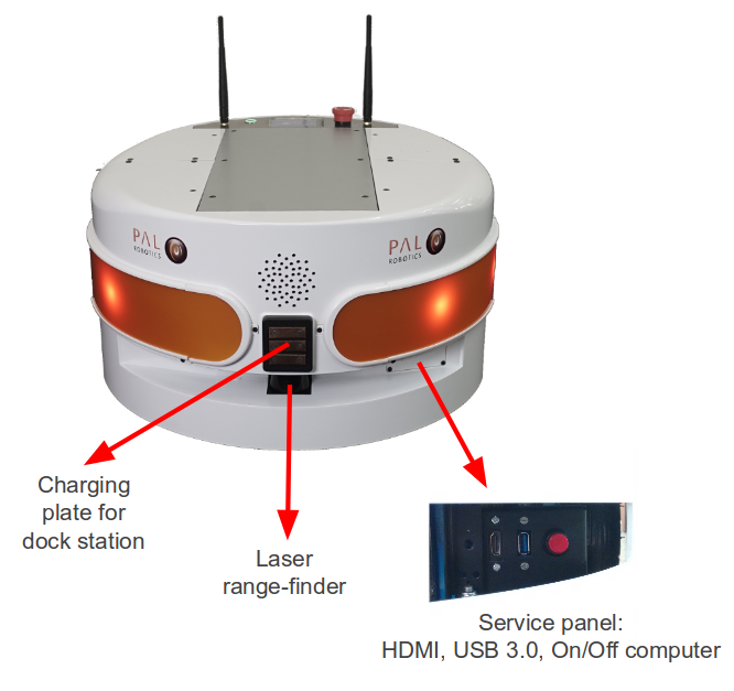
Figure: Mobile base front view
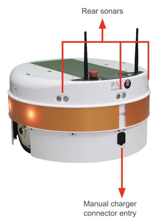
Figure: Mobile base rear view
Robot’s main specifications
Height |
30 cm |
Diameter |
54 cm |
Weight |
40 kg |
Base footprint |
Ø 54 cm |
Drive system |
Differential |
Max speed |
1 m/s |
Payload |
100 kg |
Battery |
36 V, 20 Ah |
Features of the differential mobile base
Onboard computer
The specifications of TIAGo’s onboard computer depends on the configuration options you have ordered. The different possibilities are shown in table below:
Component |
Description |
|---|---|
CPU |
Intel i5 / i7 |
RAM |
8 / 16 GB |
Hard disk |
250 / 500 GB SSD |
Wi-Fi |
802.11 a/b/g/n/ac |
Bluetooth |
Smart 4.0 Smart Ready |
Battery
The specifications of the battery supplied with TIAGo are shown in table:
Type |
Li-Ion |
|---|---|
V_nominal |
36.0 V |
V_max |
42.0 V |
V_cutoff |
30.0 V |
Nominal capacity |
20 Ah |
Nominal energy |
720 Wh |
Max. continuous discharge current |
20 A |
Pulse discharge current |
60 A |
Max. charging current |
15 A |
Charging method |
CC/CV |
Weight |
7.5 kg |
TIAGo can be equipped with two batteries. In this case, the total Nominal capacity is 1440 Wh.
Power connector
TIAGo must be charged only with suplied charger. To insert the charger connector, open the lid located on the rear part.
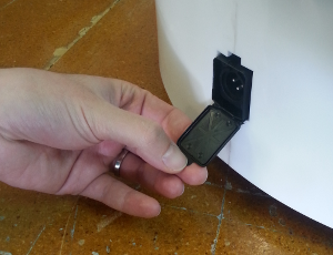
Figure: Charging connector entry
Connection Insert charging connector with metal lock facing up, push it until you hear a ‘click’.
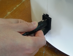
Figure: Charger connector insertion procedure
Disconnection Once charge is completed, connector can be removed. In order to do so, press metal lock and pull firmly the connector (see the figure below).
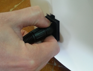
Figure: Charger connector removal procedure
Laser range-finder
The specifications of the laser on the front part of the mobile base depend on the configuration options you have ordered. The lasers supported are shown in table:
Manufacturer |
Hokuyo |
|---|---|
Model |
URG-04LX-UG01 |
Range |
0.02 - 5.6 m |
Frequency |
10 Hz |
Field of view |
180 degrees |
Step angle: |
0.36 degrees |
Manufacturer |
SICK |
|---|---|
Model |
TIM561-2050101 |
Range |
0.05 - 10 m |
Frequency |
15 Hz |
Field of view |
180 degrees |
Step angle: |
0.33 degrees |
Manufacturer |
SICK |
|---|---|
Model |
TIM571-2050101 |
Range |
0.05 - 25 m |
Frequency |
15 Hz |
Field of view |
180 degrees |
Step angle: |
0.33 degrees |
Sonars
The rear part of the mobile base has three ultrasound sensors, here referred to as sonars. One is centered and the other two are placed at 30º on the left and right. See table for the sonar’s specifications
Manufacturer |
Devantech |
|---|---|
Model |
SFR05 |
Frequency |
40 kHz |
Measure distance |
0.03 - 1 m |
IMU
The Inertial Measurement Unit is mounted at the center of the mobile base and may be used to monitor inertial forces and attitude. The specifications are presented in the table:
Manufacturer |
InvenSense |
|---|---|
Model |
MPU-6050 |
Gyroscope |
3-axis |
Accelerometer |
3-axis |
User panel
The user panel is on the top, rear part of TIAGo mobile base. It provides the buttons to power up and shutdown the robot, and a screen to give visual feedback on the robot’s status. All the specific elements of the user panel are shown in the figure below and the description of each element is presented in teh table:

Figure: User panel with and without a key lock
Number |
Name / Short description |
|---|---|
1 |
Emergency stop |
2 |
Key lock / Electric switch |
3 |
Information panel |
4 |
On / Off button |
Electric switch The electric switch is the main power control switch. Before turning TIAGo ON make sure first that this switch is ON, i.e. its red light indicator is ON. On the other hand, when TIAGo is not going to be used for a long period, please press the switch so that its red light indicator turns OFF. Note that this switch should not be turned OFF before using the On/Off button to turn OFF the onboard computer of the robot. Turning OFF this switch will cut instantaneously the power supply to all the robot components, including the onboard computer. Do not use this switch as emergency stop. For the emergency stop please refer to the next section.
Key lock
This is the main power control switch. When the robot is not going to be used for a long period of time, please turn off the power by selecting OFF position (Figure: Electric key positions).

Figure: Electric key positions
Emergency stop When pushed, motors are stopped and disconnected. Green indicator will blink fast in order to notify the emergency state.
To start the normal behaviour again, a two step validation must be executed: emergency button must be released rotating clockwise, and then On/On button must be pressed for 1 second. The green light will change to fixed state.
Information display 320x240 Color TFT display that shows battery level on the top-right corner.
On / Off button Standby control button. It is a push button with a green light to indicate the current system status.
Light |
State |
Name / Short description |
|---|---|---|
Off |
Fixed |
Standby |
On |
Fixed |
Running |
On |
Slow-Blink |
System in process of shutdown |
On |
Fast-Blink |
Emergency state |
After main power is connected, i.e. electric switch is ON (see Figure: User Panel), user must press this button during 1 second in order to start the TIAGo.
To set again the system in standby mode when is running, press again the button. The green light will blink slowly during shut down procedure and light-off when standby mode reached.
Service panel
It is possible to access the service panel by removing the cover behind the laser (see Figure: Service panel).
This service panel gives access to video, usb and on/off button of the robot’s computer. It can be used for reinstallation or debug purposes.
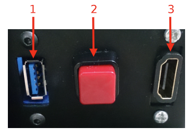
Figure: Service panel
Number |
Name / Short description |
|---|---|
1 |
USB 3.0 |
2 |
On/Off button computer |
3 |
HDMI (not in TIAGo Lite) |
Expansion Panel
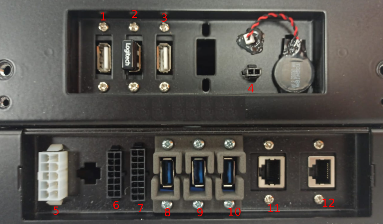
Figure: Expansion panel (this may be subject of small variations depending on version)
Number |
Name / Short description |
|---|---|
1 |
USB 2.0 |
2 |
USB 2.0 |
3 |
USB 2.0 |
4 |
Speaker |
5 |
Power expansion |
6 |
Communications expansion |
7 |
GPIOs |
8 |
USB 3.0 |
9 |
USB 3.0 |
10 |
USB 3.0 |
11 |
GbE port |
12 |
GbE port / External port |
To access the expansion panel the front part of the top metal cover should be removed, as shown in the figure below.
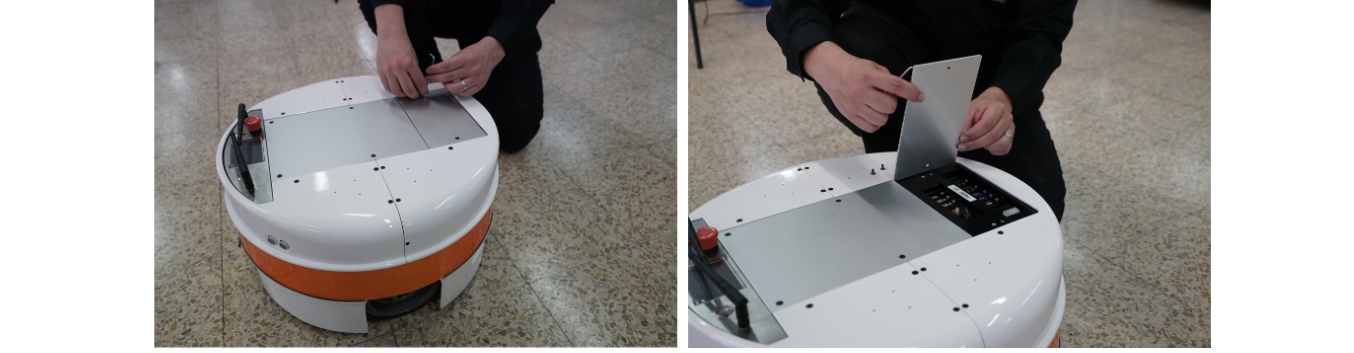
Figure: Accessing the expansion panel
Speaker connector
This expansion connector provides amplified audio output of RIGHT audio channel. Output power is 8 W max, output impedance is 8 Ohm. It is recommended to use external speaker of 8 Ohm impedance with rated power of 10 W minimum.
Connector type Molex 43020-0200, mating part is Molex 43025-0200.
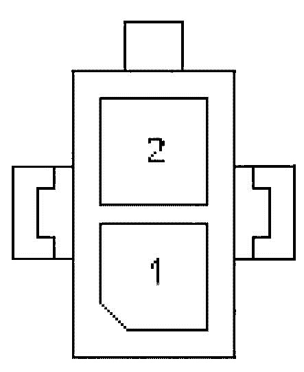
Figure: Speaker connector pinout
Pin |
Name / Short description |
|---|---|
1 |
8 Ohm, 8 W audio output, negative pin |
2 |
8 Ohm, 8 W audio output, positive pin |
Power expansion connector
This expansion connector provides access to the battery and provide up to 360 W. Battery voltage can vary depending on actual State Of Charge in the range of 30V to 42V.
It is recommended to use the all 3 battery output pins in parallel to divide current between them. The maximum current that can be provided through these battery pins is 10 A in total, approximately.
Connector type Molex 39012101, mating part is Molex 39012100.
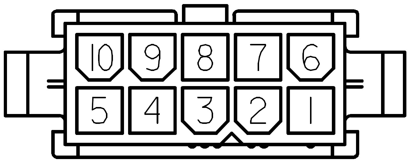
Figure: Power expansion connector pinout
Communications expansion connector
This expansion connector provides access to internal communication buses of the robot. There are 2 CAN buses for motors and actuators and a propietary bus for sensors. Only the CAN buses are available to the user. CAN bus speed is 1Mbit/s.
Connector type Molex 43020-1400, mating part is Molex 43025-1400.

Figure: Communication expansion connector pinout
Number |
Name / Short description |
|---|---|
1 |
CANL of LEFT bus |
2 |
Shield of LEFT bus |
3 |
CANH of LEFT bus |
4 |
reserved |
5 |
reserved |
6 |
reserved |
7 |
n.c. |
8 |
CANL of RIGHT bus |
9 |
Shield of RIGHT bus |
10 |
CANH of RIGHT bus |
11 |
n.c. |
12 |
n.c. |
13 |
n.c. |
14 |
n.c. |
GPIOs
This expansion connector provides access to General Purpose Input (GPI) and Output (GPO) pins.
Connector type Molex 43020-1600, mating part is Molex 43025-1600.
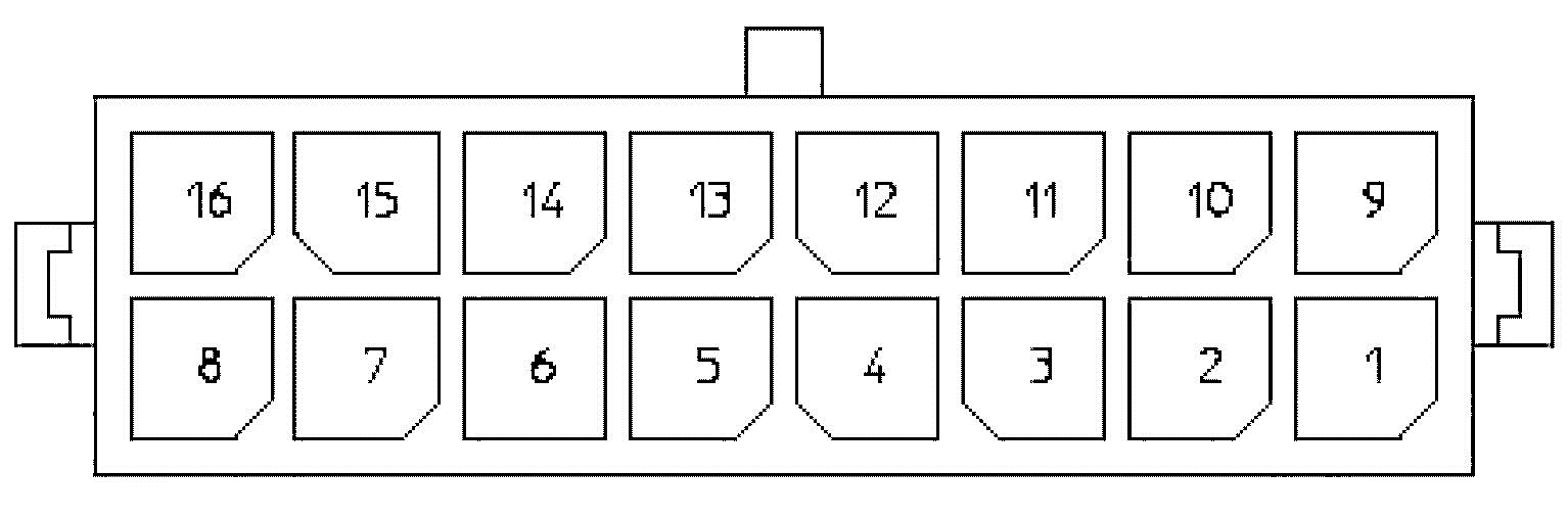
Figure: GPIOs connector pinout
Number |
Name / Short description |
|---|---|
1 |
|
2 |
|
3 |
|
4 |
+5V |
5 |
GPO 0 (5V TTL level) |
6 |
GPO 1 (5V TTL level) |
7 |
GPO 2 (5V TTL level) |
8 |
GPO 3 (5V TTL level) |
9 |
|
10 |
|
11 |
|
12 |
GND |
13 |
GPI 0 (5V TTL level) |
14 |
GPI 1 (5V TTL level) |
15 |
GPI 2 (5V TTL level) |
16 |
GPI 3 (5V TTL level) |
General purpose outputs are referenced to pin 12 GND and by default are set to low level. On the other hand, general purpose inputs must be set using pin 4 +5V for high level and pin 12 GND for low level, and have an internal default pull-up.
Expansion Plate
The metal plate on the top of the TIAGo Base could be use for mounting additional componets. The thread distances are shown in Figure: Expansion plate for integration of upper body that will appear in the Electrical parts and components section and the screws to use are M4 type.
Connectivity
TIAGo is equipped with a dual band Wireless 802.11b/g/n/ac interface, plus bluetooth 4.0 and a WiFi antenna. When the WiFi interface is configured as access point, it has a 802.11g interface.
There are two Gigabit Ethernet ports, ports 2 and 3 in the expansion panel figure, that can be used to connect to the robot’s internal network. For this network, the IP address range 10.68.0.0/24 has been reserved.
Caution
The IP addresses used in the building network MUST not use this range because it can interfere with the robot’s services.
Electrical parts and components
Neither TIAGo Base nor any of its electrical components and mechanical parts are connected to an external ground. The chassis and all electromechanical components of the robot are physically isolated from the environment ground with the isolated rubber under its feet. To avoid any damage in the electromechanical part of TIAGo Base don’t touch any metallic parts directly to avoid discharges.
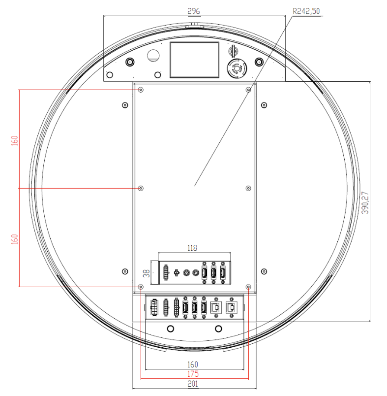
Figure: Expansion plate for integration of upper body
Electrical power supply and connectors
The power source supplied with TIAGo Base is compliant with the directive on the restriction of the use of certain hazardous substances in electrical and electronic equipment 2002/95/EC (RoHS) and compliant with the requirements of the applicable EC directives, according to the manufacturer. The power source is connected to the environment ground, whenever the supplied wire is used (Phase-Neutral-Earth).