Visual programming
Overview
The Visual Programming is a web based app used to create programs for the robot in a simple and user friendly way. It consists in creating graph structures to manage actions that need to happen in a specific order using nodes. Each node in the graph is an action with a unique ID and tells the system what to do next. For most nodes, error handling can be configured to either, do something in case of error, or ignore it.
The Visual Programming web app consists of a Start page, a list of previously created programs and ways to manage them, and an Editor page, where program graphs can be created or edited.
Start page
The visual programming home page displays a New Program button and a list of programs previously created.
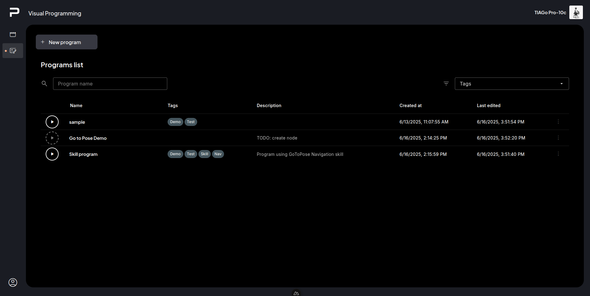
Programs list
Filter bar
Filter the list by the program name, or the tags assigned to the programs.
List
Each list item shows, from left to right:
 Play button
Program name
Tags
Description
Created at date
Updated at date
Context menu
Clicking the starts the program. The  appears to
stop execution. While a program is running, other programs are disabled.
appears to
stop execution. While a program is running, other programs are disabled.
If the play button has a dashed border and is disabled  , the
program’s graph is incomplete and cannot be executed.
, the
program’s graph is incomplete and cannot be executed.
Click the program name to open it in the editor.
Programs can be tagged to group or filter them.
A description can be added to each program.
Each program has a created date, and if a program has been updated it will also display a “Last edited”.
Clicking on the three dots opens the context menu for that program to:
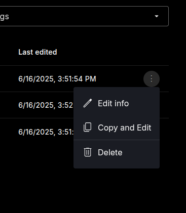
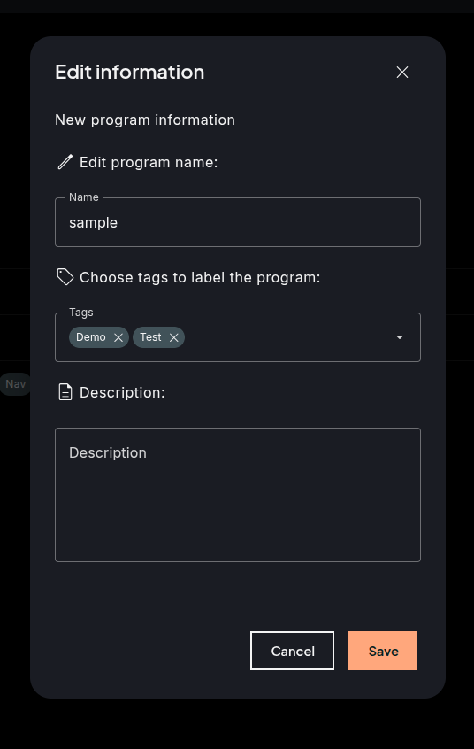
Edit information (name, tags, and description), opens a popup with the different fields to be edited.
Copy and edit, use the existing program data to create another program. It opens the editor.
Delete, clicking it will open a prompt to confirm deletion. This action is irreversible.
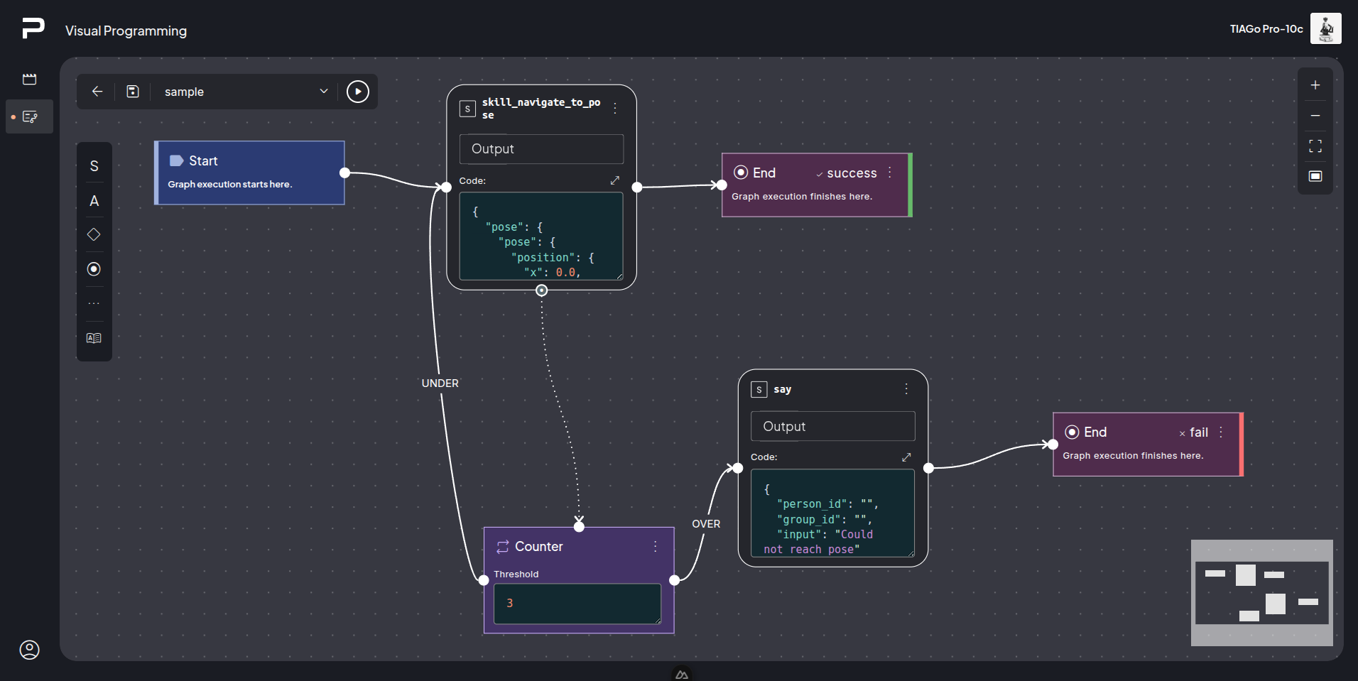
Editor
The visual programming editor allows the editing of a program’s graph structure via nodes, connections, and properties.
The UI of th editor is divided into the following part:
Top left panel
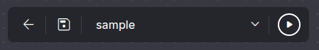
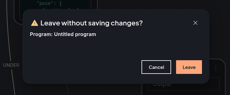
The top left panel has a back button, which goes back to the programs list page. It opens a prompt before if there are some unsaved changes to confirm exiting.
Save button to save the changes, the save button icon will display a small colored circle if there are any unsaved changes.
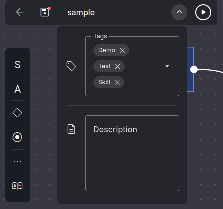
Field with the program name, and a collapsable menu to edit tags and description.
Finally, the play button to run the program on the editor.
Top right controls panel
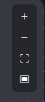
This panel contains options to control the workspace visualization, such as zooming in and out, fitting the graph into view, and taking a screenshot of the editor, which is automatically downloaded as an image.
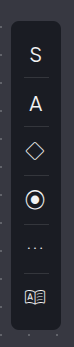
Nodes menu
The nodes menu on the left of the editor is available to select the different types of nodes offered.
Different type of nodes available:
Executor nodes
Executor nodes refer to the type that executes some sort of code and can return a result that can be used later. These are: Skill nodes, Simple API nodes, and Python nodes.
Control nodes
The control nodes manage the flow of program, these include the If node and the Counter node
End nodes
The end node finishes the flow of the program graph or subgraphs; there is the End Success node, the End Failure node, and the End Subgraph node.
Signal nodes
Signal nodes are used to initiate, emit, or respond to events within a visual programming graph. They act like triggers — sending or reacting to “signals” that control when other parts of the program should start or react. This type includes Emitter node, Wait for Signal node, and Slot node.
The nodes menu has the following submenus:
Skill nodes menu
Simple API menu
Flow control menu
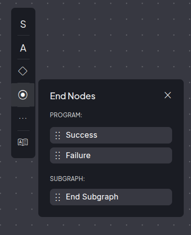
End nodes menu
Advanced menu
Variables menu
Nodes
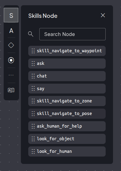
Skill node
A skill node represents a call to a skill.
The node allows a JSON-encoded object to be sent to the skill as arguments for that skill, which can use intermediate “variables” to offer further configuration, and allows the user to store the response in a variable that can be used later.
The skill nodes can be found in the Skills submenu on the Nodes menu.
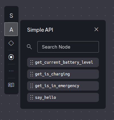
Simple API node
Simple API nodes are nodes that call methods exposed by the Simple API. Those methods might receive parameters as needed, and their results can be stored for later use.
The Simple API nodes are located in the submenu of simple API
Python node
The python node evaluates a valid python expression and returns its result.
The python node is located in the advanced sub menu.
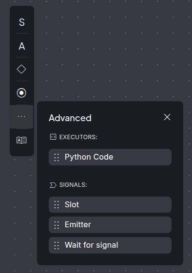
Slot node
A slot node is a node from which code will start to be executed in response to a signal.
The Slot node is located in the advanced sub menu.
Emitter node
Emits a signal, to start a Slot node or a Wait For Signal node that is started with the emitted signal as an initiator.
The Emitter node is located in the advanced sub menu.
“Wait for signal” node
Waits for a specific signal to be emitted and blocks execution until then. The Wait for Signal node is located in the advanced sub menu.
IF node
An if node evaluates a given python expression that returns a boolean value, and chooses the next node depending on that value.
The IF node can be found in the Flow control menu.
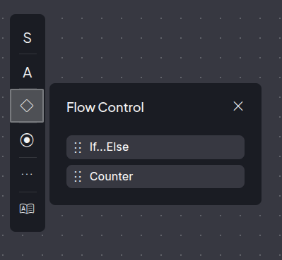
Counter node
The Counter node increments a counter each time it’s executed. If this count remains below a set threshold, the execution flow follows the “under” edge. Once the count exceeds the threshold, the flow transitions via the “over” edge.
The Counter node can be found in the Flow control menu.
End node
An end node finishes execution for the current graph or subgraph.
There are the three types of End nodes:
End success: Finish the execution of the entire program in Success
End failure: finish the execution of the entire program in Failure
End subgraph: finish the current subgraph.
The end nodes can be found in the End nodes submenu.
10. Start node The start node is where the execution of the program starts, there can only be one Start node for the program.
The start node can not be added or removed from the program.
Variables
A program can make use of variables, which are stored globally for that specific program and used throughout the graph.
Variables can be created by storing the result of the executor nodes return value, and then can be used in inputs for other nodes.
All created variables, if any, are found in the Variables menu.
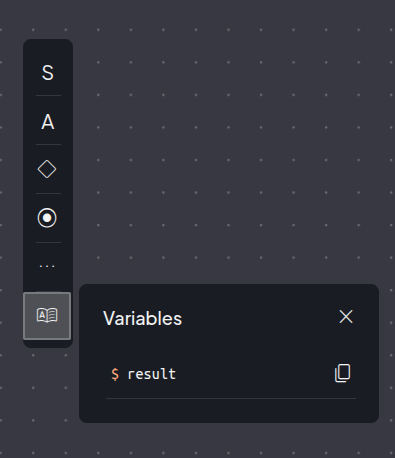
An example of creating a variable:
The created variables can be used in other nodes, where they will be replaced by the actual value.
The variable can be dragged from the menu and dropped in a node input, it will be appended at the end of that input, the Copy button can be used to copy on the clipboard and paste at the desired location, and also the variable name can be just typed in directly into the input preceded by the $ sign.

Editor workspace
Interaction with the editor workspace.
The mouse wheel can be used to zoom in and out
Click on the editor and drag to move around the workspace
Click on a node in the workspace and drag it to move it around
Click on the context menu of a node, all nodes will show an option to delete the node. Nodes can also be deleted by clicking on the node to select and then pressing Backspace key or Delete button. Executor node types will also show an option to ignore or handle failure. If handle failure is used it will show an error edge source handle which can be connected to another node in case the node execution fails.
Add nodes to the graph by opening the nodes menu and dragging on from there or click on the node from the menu and it will appear in the middle of the editor.
Click on a source edge handle and drag to connect to an input edge handle.
Click on an existing edge to select it, this will open a context menu for edge where it has an option to delete the edge, or use the Backspace key or Delete button to remove the edge.
Hold down the Shift key, click and move the mouse to perform a multiselect of nodes where they can be all deleted, or moved around.
Graph errors panel
In case there are some errors in the graph, all of them will be displayed in the graph error panel at bottom left of the editor.
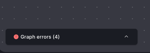
Collapsed graph error panel
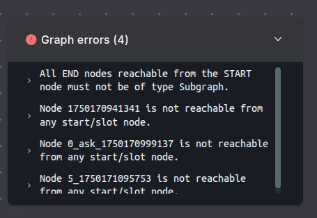
Expanded graph error panel
Minimap
Shows a minimap of the graph, it is located at the bottom right corner of the editor.
Rules for graphs
For a created visual programming to be playable it needs to meet certain requirements:
All nodes except End Nodes must point to another node.
All nodes except Start and Slot nodes must be pointed by another node or nodes.
All Nodes except IF nodes or Counter nodes must point to a Node that is not their ancestor.
In the case of IF and Counter nodes, the False or Under edge can be connected to an ancestor node to create a loop.
A graph can only have one Start node.
All End nodes that can be reached from the Start Node must finish the program, either with success or failure.
A graph must emit all signals that are used either in Slot nodes or in Wait for Signal nodes.
All emitted signals must be reacted to by either a Slot node, or a Wait for Signal node.