1 TIAGo OMNI Base handbook
2 Package contents
2.1 Overview
This section includes a list of items and accessories that come with TIAGo OMNI Base. Make sure they’re all present:
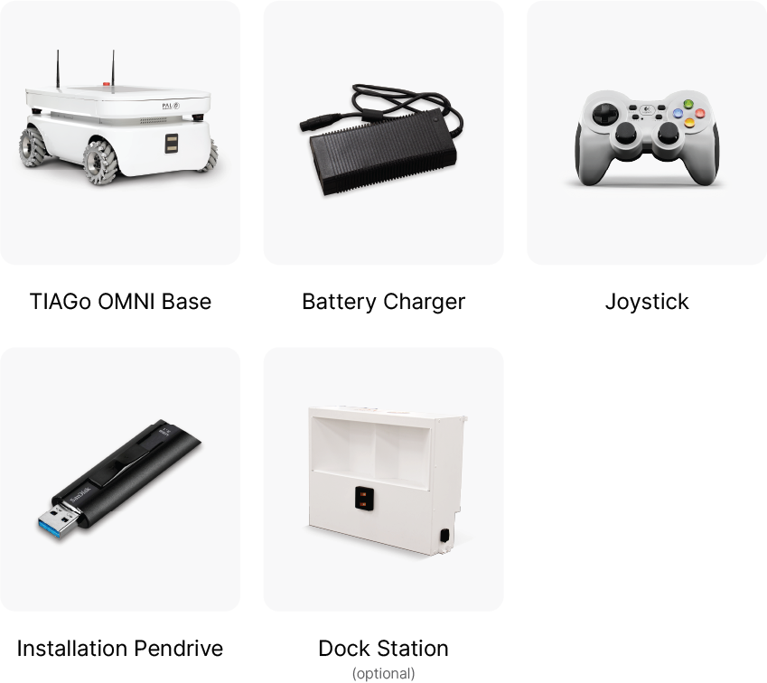
Figure: Components inside transportation box
Furthermore, a set of physical keys is provided for authorized personnel to facilitate the switching on and off of the robot.
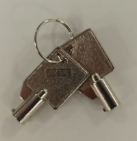
Figure: Physical keys
3 Specifications
3.1 Robot overview
TIAGo OMNI Base’s main specifications are summarized in the tables below.
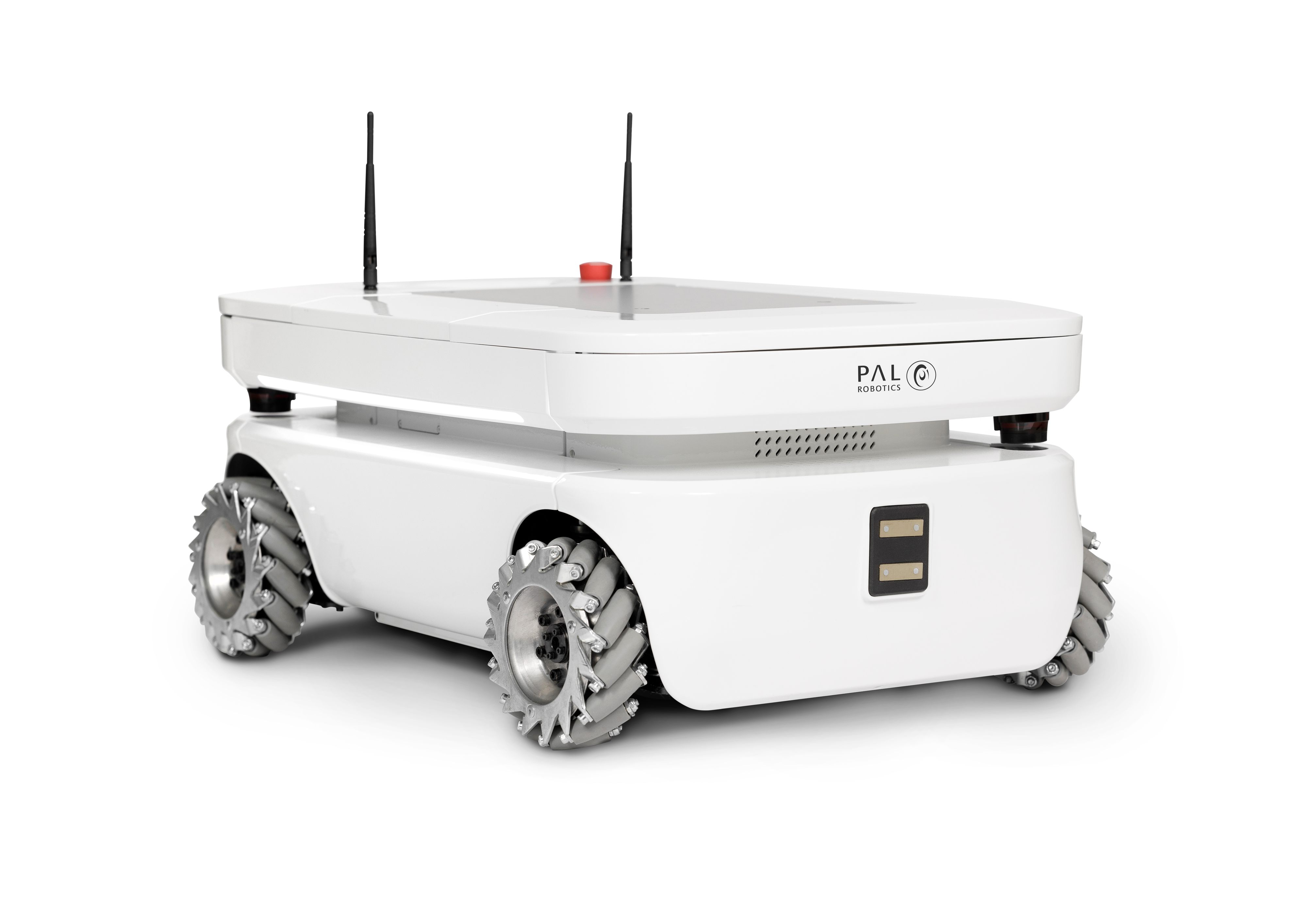
Figure: TIAGo OMNI Base
Robot’s main specifications:
Height |
31 cm |
Weight |
48 Kg |
Base footprint |
72 * 50 cm |
Drive system |
Omnidirectional |
Max speed |
1 m/s |
Payload |
150 kg |
Battery |
2 x 36 V, 20 Ah |
3.2 Mobile base
TIAGo ’s mobile base is provided with a omnidirectional drive mechanism and contains an onboard computer, batteries, power connector, two laser-rangefinder, a user panel, a service panel and two WiFi networks to ensure wireless connectivity. Furthermore, the version of TIAGo with a docking station has a charging plate on the front.
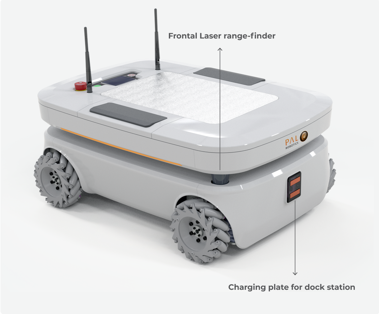
Figure: Mobile base front view
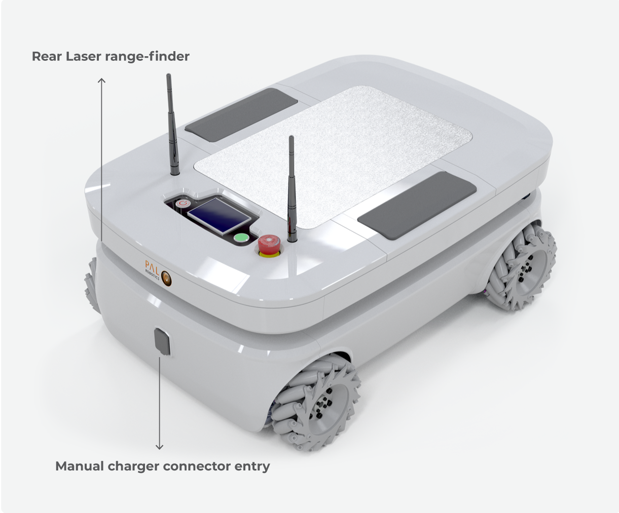
Figure: Mobile base rear view
3.2.1 Onboard computer
The specifications of TIAGo ’s onboard computer depends on the configuration options you have ordered. The different possibilities are shown in table below:
Component |
Description |
|---|---|
CPU |
Intel i5 / i7 |
RAM |
8 / 16 GB |
Hard disk |
250 / 500 GB SSD |
Wi-Fi |
802.11 a/b/g/n/ac |
Bluetooth |
Smart 4.0 Smart Ready |
3.2.2 Battery
The specifications of the battery supplied with TIAGo are shown in table below:
Type |
Li-Ion |
|---|---|
V_nominal |
36.0 V |
V_max |
42.0 V |
V_cutoff |
30.0 V |
Nominal capacity |
20 Ah |
Nominal energy |
720 Wh |
Max. continuous discharge current |
20 A |
Pulse discharge current |
60 A |
Max. charging current |
15 A |
Charging method |
CC/CV |
Weight |
7.5 kg |
TIAGo OMNI Base can be equipped with two batteries. In this case, the total Nominal capacity is 1440 Wh.
3.2.3 Power connector
TIAGo OMNI Base must only be charged only with the supplied charger. To insert the charger connector, open the lid located on the rear part of the robot, as shown in Figure: Connector entry
Connection Insert charging connector with metal lock facing up and push it, as shown in Figure: Connector entry b , until you hear a ’click’.
Disconnection Once charge is completed, connector can be removed. In order to o remove it, press metal lock and pull the connector firmly, see Figure: Connector entry.
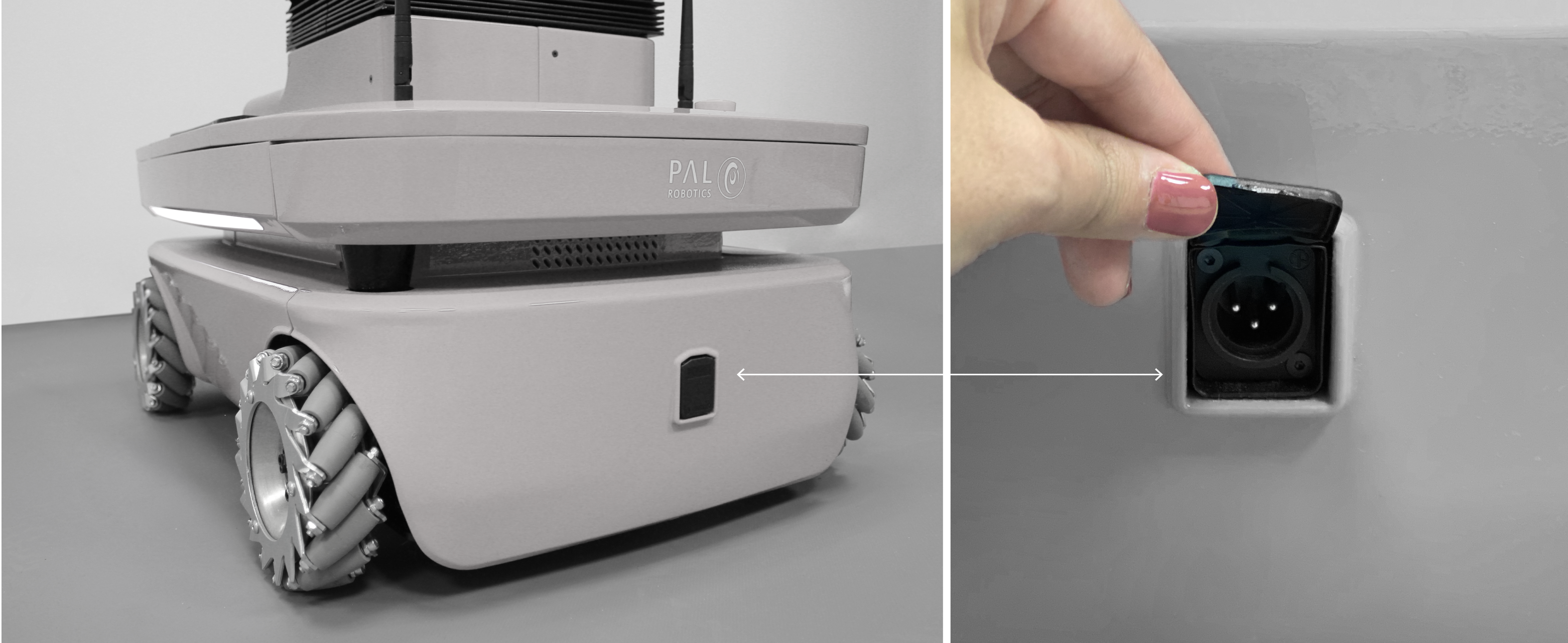
Figure: Connector entry
3.2.4 Laser range-finder
The specifications of the laser on the front part of the mobile base depend on the configuration options you have ordered. The lasers supported are shown in table:
Manufacturer |
Hokuyo |
|---|---|
Model |
URG-04LX-UG01 |
Range |
0.02 - 5.6 m |
Frequency |
10 Hz |
Field of view |
180 degrees |
Step angle: |
0.36 degrees |
Manufacturer |
SICK |
|---|---|
Model |
TIM561-2050101 |
Range |
0.05 - 10 m |
Frequency |
15 Hz |
Field of view |
180 degrees |
Step angle: |
0.33 degrees |
Manufacturer |
SICK |
|---|---|
Model |
TIM571-2050101 |
Range |
0.05 - 25 m |
Frequency |
15 Hz |
Field of view |
180 degrees |
Step angle: |
0.33 degrees |
3.2.5 IMU
The Inertial Measurement Unit is mounted at the center of the mobile base and may be used to monitor inertial forces and attitude. The specifications are presented in the table:
Manufacturer |
InvenSense |
|---|---|
Model |
MPU-6050 |
Gyroscope |
3-axis |
Accelerometer |
3-axis |
3.2.6 User panel
The user panel is on the top, rear part of TIAGo OMNI Base. It provides the buttons to power up and shutdown the robot, and a screen to give visual feedback on the robot’s status. All the specific elements of the user panel are shown in the figure below and the description of each element is presented in the table below:
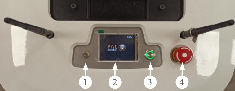
Figure: User Panel
Number |
Name / Short description |
|---|---|
1 |
Electric key lock |
2 |
Information display (optional) |
3 |
On / Off button |
4 |
Emergency stop |
Electric key lock This is the main power control switch. When TIAGo OMNI Base is not going to be used for a long period of time, please turn off the power by selecting OFF position as shown in the following figure:
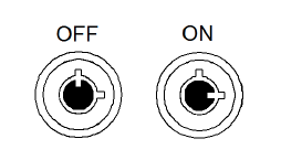
Figure: Electric Key Lock
Emergency stop When pushed, motors are stopped and disconnected. The green indicator of the On/Off button will blink fast in order to notify the user of the emergency state.
To start normal behaviour again, a two step validation process must be executed: the emergency button must be released by rotating clockwise, and then the On/Off button must be pressed for one second. The green light indicator of the On/Off button will change to a fixed state.
Information display 320x240 Color TFT display shows the battery level on the top right corner.
On / Off button he standby control button is a pushbutton with a green light that indicates the system’s current status.
Light |
State |
Name / Short description |
|---|---|---|
Off |
Fixed |
Standby |
On |
Fixed |
Running |
On |
Slow-Blink |
System in process of shutdown |
On |
Fast-Blink |
Emergency state |
After main power is connected, i.e. electric switch is ON (Figure: User panel), user must press this button during 1 second in order to start the TIAGo OMNI Base.
To re-set the system in standby mode when the robot is running, press the button again. The green light will blink slowly during shutdown procedure and light-off when standby mode reached.
3.2.7 Panels for the user
3.2.7.1 Service panel
The frontal white top cover (which is attached with magnets) needs to be removed to access the service panel (see figure Figure: Service panel).
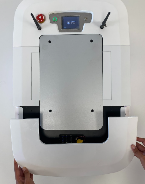
Figure: Service panel
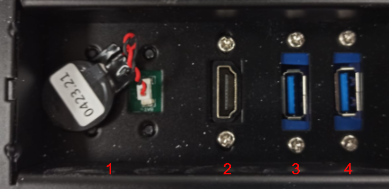
Number |
Name / Short description |
|---|---|
1 |
Computer BIOS battery |
2 |
HDMI port |
3 |
USB 3 |
4 |
USB 3 |
3.2.7.2 Expansion panel
In order to access this panel the top plate of the robot must be removed.
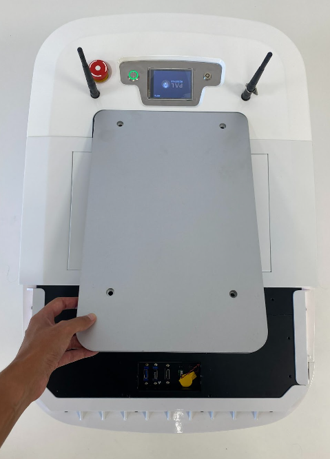
Mounting plate must be removed in order to get access to this panel.
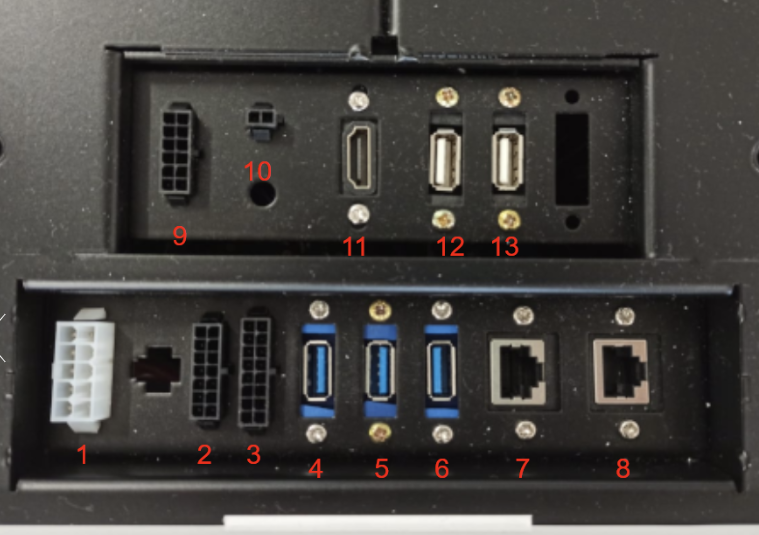
Number |
Name / Short description |
|---|---|
1 |
Power connector |
2 |
Communications Expansion, i.e. CAN (if ordered) |
3 |
GPIOs |
4 |
USB 3 |
5 |
USB 3 |
6 |
USB 3 |
7 |
Ethernet |
8 |
Ethernet |
9 |
Reserved |
10 |
Speaker |
11 |
HDMI |
12 |
USB 2 |
13 |
USB 2 |
Power connector
This expansion connector provides access to the battery and provide up to 360 W. Battery voltage can vary depending on actual State Of Charge in the range of 30V to 42V.
It is recommended to use the all 3 battery output pins in parallel to divide current between them. The maximum current that can be provided through these battery pins is 10 A in total, approximately.
Connector type Molex 39012101, mating part is Molex 39012100.
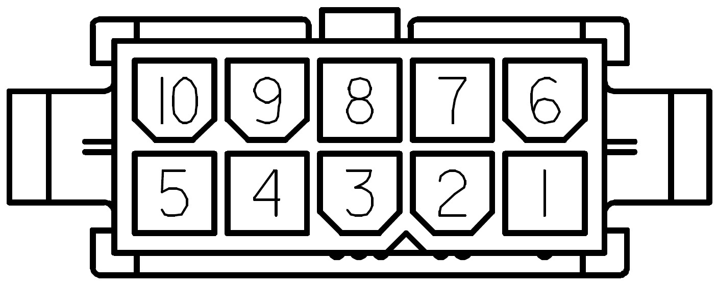
Figure: Power expansion connector pinout
Pin |
Name / Short description |
|---|---|
1 |
|
2 |
+12V output (max 4.5A shared with SICK Laser if present) |
3 |
Battery output (max 9A/pin) |
4 |
Battery output (max 9A/pin) |
5 |
Battery output (max 9A/pin) |
6 |
|
7 |
GND of 12V output |
8 |
Battery GND |
9 |
Battery GND |
10 |
Battery GND |
Communications expansion
This expansion connector provides access to internal communication buses of the robot. There are 2 CAN buses for motors and actuators and a propietary bus for sensors. Only the CAN buses are available to the user. CAN bus speed is 1Mbit/s.
Connector type Molex 43020-1400, mating part is Molex 43025-1400.
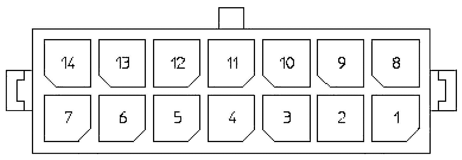
Figure: Communication expansion connector pinout
Number |
Name / Short description |
|---|---|
1 |
CANL of LEFT bus |
2 |
Shield of LEFT bus |
3 |
CANH of LEFT bus |
4 |
reserved |
5 |
reserved |
6 |
reserved |
7 |
n.c. |
8 |
CANL of RIGHT bus |
9 |
Shield of RIGHT bus |
10 |
CANH of RIGHT bus |
11 |
n.c. |
12 |
n.c. |
13 |
n.c. |
14 |
n.c. |
GPIOs
This expansion connector provides access to General Purpose Input (GPI) and Output (GPO) pins.
Connector type Molex 43020-1600, mating part is Molex 43025-1600.

Figure: GPIOs connector pinout
Number |
Name / Short description |
|---|---|
1 |
|
2 |
|
3 |
|
4 |
+5V |
5 |
GPO 0 (5V TTL level) |
6 |
GPO 1 (5V TTL level) |
7 |
GPO 2 (5V TTL level) |
8 |
GPO 3 (5V TTL level) |
9 |
|
10 |
|
11 |
|
12 |
GND |
13 |
GPI 0 (5V TTL level) |
14 |
GPI 1 (5V TTL level) |
15 |
GPI 2 (5V TTL level) |
16 |
GPI 3 (5V TTL level) |
General purpose outputs are referenced to pin 12 GND and by default are set to low level. On the other hand, general purpose inputs must be set using pin 4 +5V for high level and pin 12 GND for low level, and have an internal default pull-up.
3.2.8 Connectivity
TIAGo is equipped with a dual band Wireless 802.11b/g/n/ac interface, plus bluetooth 4.0 and a WiFi antenna. When the WiFi interface is configured as access point, it has a 802.11g interface.
There are two Gigabit Ethernet ports, ports 2 and 3 in the expansion panel figure, that can be used to connect to the robot’s internal network. For this network, the IP address range 10.68.0.0/24 has been reserved. The IP addresses used in the building network MUST not use this range because it can interfere with the robot’s services.
3.3 Electrical parts and components
Neither TIAGo OMNI Base nor any of its electrical components or mechanical parts are connected to external ground. The chassis and all electromechanical components are physically isolated from the ground by the isolation rubber under its feet. Avoid touching any metal parts directly to prevent discharges and damage to TIAGo OMNI Base’s electromechanical parts.
Electrical power supply and connectors
The power source supplied with TIAGo OMNI Base is compliant with the Directive on the restriction of the use of certain hazardous substances in electrical and electronic equipment 2002/95/EC (RoHS) and with the requirements of the applicable EC directives, according to the manufacturer. The power source is connected to the environment ground, whenever the supplied wire is used (Phase-Neutral-Earth).
4 Storage
4.1 Overview
This section contains information relating to the storage of TIAGo OMNI Base.
4.2 Unboxing TIAGo OMNI Base
This section explains how to unbox TIAGo OMNI Base safely. TIAGo OMNI Base is shipped with the flightcase shown in figure:
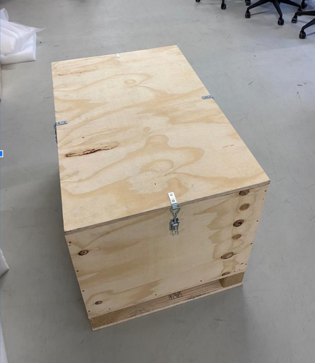
Figure: TIAGo OMNI Base flightcase
The flightcase MUST be always transported flat as shown in picture 7 to ensure the robot’s safety.
The lid of the box is used as a ramp to go up the omnidirectional base (1). The ramp is removed and these 4 foams are put under pressure (2). The foams are pressed with the side cover so that the base is fixed. And the Dock Station is placed (3). The Wi-Fi antennas are folded, and the accessories box is placed (4), The set is covered with the upper foam, matching the hole in the foam with the antennas and the emergency button (5). Place the end lid and center the foam so that everything fits (6). Ready to transport and move (7).
Do not pull on any part of the omni base cover, as it could cause damage to you or the robot.
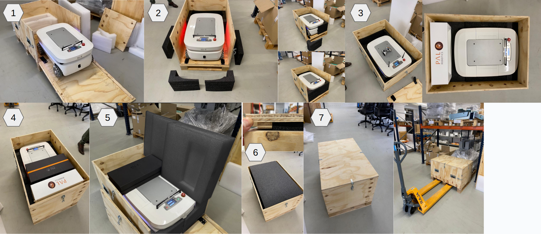
Figure: Boxing procedure
5 Storage cautions
Always store TIAGo OMNI Base in a place where it will not be exposed to weather conditions.
The storage temperature range for TIAGo OMNI Base is between 0ºC ∼ +60ºC.
The storage temperature range for the batteries is between +10ºC ∼ +35ºC.
It is recommended to turn completly off (red power button is off) the TIAGo OMNI Base when the storage period exceeds two weeks.
It is recommended to charge the battery to 50% when storing it for more than two weeks.
Avoid the use or presence of water near TIAGo OMNI Base.
Avoid any generation of dust close to TIAGo OMNI Base.
Avoid the use or presence of magnetic devices or electromagneticfields near TIAGo OMNI Base.
6 Introduction to safety
6.1 Overview
Safety is important when working with TIAGo OMNI Base. This chapter provides an overview of safety issues, general usage guidelines to maintain safety, and some safety-related design features. Before operating the robot, all users must read and understand this chapter!
6.2 Intended applications
It is important to clarify the intended usage of the robot prior to any kind of operation.
TIAGo OMNI Base is a robotics research and development platform designed to be operated in a controlled environment, under supervision by trained staff at all times
- The hardware and software of TIAGo OMNI Base enables research and development of activities in the following areas:
Navigation and SLAM
6.3 Working environment and usage guidelines
The working temperatures are:
Robot: +10ºC ~ +35ºC
The space where TIAGo OMNI Base operates should have a flat floor and be free of hazards. Specifically, stair-ways and other drop offs can pose an extreme danger. Avoid sharp objects (such as knives), sources of fire, hazardous chemicals, or furniture that could be knocked over.
Maintain a safe environment:
The terrain for TIAGo OMNI Base usage must be capable of supporting the weight of the robot (see Specifications section). It must be horizontal and flat. Do not use any carpet, to avoid tripping over.
Make sure the robot has adequate space for any expected or unexpected operation.
Make sure the environment is free of objects that could pose a risk if knocked, hit, or otherwise affected by TIAGo OMNI Base.
Make sure there are no cables or ropes that could be caught in the covers or wheels; these could pull other objects over.
Make sure no animals are near the robot.
Be aware of the location of emergency exits and make sure the robot cannot block them.
Do not operate the robot outdoors.
Keep TIAGo OMNI Base away from flames and other heat sources.
Do not allow the robot to come in contact with liquids.
Avoid dust in the room.
Avoid the use or presence of magnetic devices near the robot.
Apply extreme caution with children.
6.4 Battery manipulation
The following guidelines must be respected when handling the robot in order to prevent damage to the robot’s internal batteries.
Do not expose to fire.
Do not expose the battery to water or salt water, or allow the battery to get wet.
Do not open or modify the battery case.
Do not expose to ambient temperatures above 49ºC for over 24 hours.
Do not store in temperatures below -5ºC over seven days.
For long term storage (more than 1 month) charge the battery to 50%.
Do not use the TIAGo OMNI Base’s batteries for other purposes.
Do not use other devices but the supplied charger to recharge the battery.
Do not drop the batteries.
If any damage or leakage is observed, stop using the battery.
7 Safety measures in practice
7.1 Emergency stop
The emergency stop button can be found on the back of the robot between the power button and the battery level display. As the name implies this button may be used only in exceptional cases where the immediate stop of the robot is required.
To activate the emergency stop the user has to push the button. To deactivate the emergency stop the buttonhas to be rotated clockwise according to the indications on the button until it pops out.
- Pushing the Emergency button turns off the power of the robot. All electronic components of the robot, hardware controllers and computers included will be powered down. Be careful using this emergencystop action because the motors will be switched OFF.
After releasing the emergency stop button the user has to start the robot by using the power button.
7.2 Firefighting equipment
For correct use of TIAGo OMNI Base in a laboratory or location with safety conditions, it is recommended to have in place a C Class or ABC Class fire extinguisher (based on halogenated products), as these extinguishers are suitable for stifling an electrical fire.
If a fire occurs, please follow these instructions:
Call the firefighters.
Push the emergency stop button, as long as you can do so without any risk.
Only tackle a fire in its very early stages.
Always put your own and others’ safety first.
Upon discovering the fire, immediately raise an alarm.
Make sure the exit remains clear.
Fire extinguishers are only suitable for fighting a fire in its very early stages. Never tackle a fire if it is starting to spread or has spread to other items in the room, or if the room is filling with smoke.
If you cannot stop the fire or if the extinguisher runs out, get yourself and everyone else out of the building immediately, closing all doors behind you as you go. Then ensure the fire brigade are on their way.
7.3 Leakage
The battery is the only component of the robot that is able to leak. To avoid leakage of any substance from the battery, follow the instructions defined in section of storage_base, to ensure the battery is manipulated and used correctly
8 Robot Identification
The robot is identified by a physical label that can be found close to the power connector.
This label contains:
Business name and full address.
Designation of the machine.
Part Number (P.N.).
Year of construction.
Serial number (S.N.).

Figure: Identification label
9 Software recovery
9.1 Overview
This section explains the System and Software reinstall procedure for TIAGo OMNI Base.
9.2 Robot computer installation
To begin the installation process, plug a monitor and USB keyboard into the HDMI connector of the user panel.
BIOS configuration: Some options in the Control BIOS computer must be configured as follows:
Turn on the robot and press F2 repeatedly. Wait until the BIOS menu appears.
In System Performance, select ASUS Optimal.
Enter Advance Mode by pressing F7.
- In the Advanced > CPU Configuration menu:
Set Intel Adaptive Thermal Monitor to Disabled
Set Intel Virtualization Technology to Disabled.
- In the Advanced > CPU Configuration > CPU Power Management Configuration menu:
Set EIST to Disabled.
Set CPU C states to Disabled.
- In the Boot menu:
Set Wait for F1 if error to Disabled.
Go to Exit and select Save Changes & Reset.
Shut down the robot.
Installation: The installation is performed using the Software USB drive provided with TIAGo OMNI Base.
Insert the Software USB drive.
Turn on the robot and press F2 repeatedly. Wait until the BIOS menu appears.
Enter the Boot Menu by pressing F8 and select the Software USB drive.
The Language menu will pop up. Select English.
The menu shown in figure below.
Select Install TIAGo OMNI Base.
Select the keyboard layout by following the instructions.
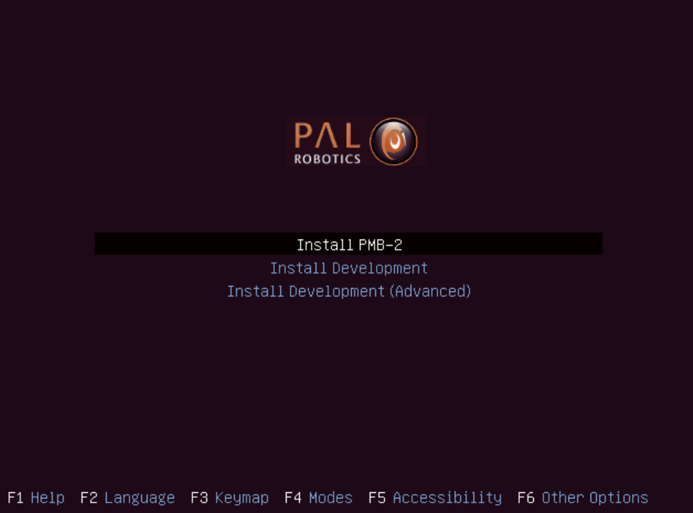
Figure: System installation menu
9.3 Development computer installation
Hardware installation: Connect the computer to the electric plug, the mouse and the keyboard. Internet access is not required as the installation is self-contained.
Software Installation: The installation is performed using the Software USB drive provided with TIAGo OMNI Base.
Insert the Software USB drive.
Turn on the computer, access the BIOS and boot the Software USB drive.
The Language menu will pop up. Select English.
The menu shown in next figure.
Choose Install Development (Advanced) if you wish to select a target partition in the development computer. Using the “Install Development” option will delete all partitions in the disk and automatically install the system in a new partition.
Select the keyboard layout by following the instructions.
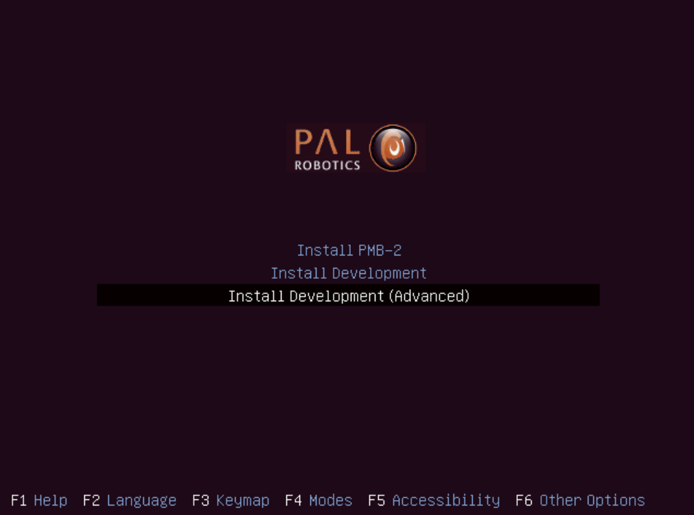
Figure: System installation menu
10 TIAGo OMNI Base Robot’s Internal Computers
10.1 TIAGo OMNI Base LAN
The name of TIAGo OMNI Base’s computer is omnibase-0c, where 0 needs to be replaced by the serial number of your robot. For the sake of clarity, hereafter we will use omnibase-0c to refer to TIAGo OMNI Base’s computer name.
In order to connect ot the robot, use ssh as follows:
ssh pal@omnibase-0c
10.2 Users
The users and default passwords in the TIAGo OMNI Base computers are:
root: Default password is palroot.
pal: Default password is pal.
aptuser: Default password is palaptuser
10.3 File system
The TIAGo OMNI Base robot’s computer has a protection against power failures that could corrupt the filesystem.
These partitions are created:
/: This is an union partition, the disk is mounted in /ro directory as read-only and all the changes arestored in RAM. So, all the changes are not persistent between reboots.
/home: This partition is read-write. Changes are persistent between reboots.
/var/log: This partition is read-write. Changes are persistent between reboots.
In order to work with the filesystem as read-write do the following:
root@omnibase-0c:~# rw
Remounting as rw...
Mounting /ro as read-write
Binding system files...
root@omnibase-0c:~# chroot /ro
rw command remounts all the partitions as read-write. Then with a chroot to /ro we have the same system than the default but all writable. All the changes performed will be persistent.
In order to return to the previous state do the following:
root@omnibase-0c:~# exit
root@omnibase-0c:~# ro
Remount /ro as read only
Unbinding system files
First exit command returns from the chroot. Then the ro script remounts the partitions in the default way.
10.4 Internal DNS
The control computer has a DNS server that is used for the internal LAN of the TIAGo OMNI Base with the domain name reem-lan. This DNS server is used by all the computers connected to the LAN.
When a computer is added to the internal LAN (using the Ethernet connector, for example) it can be added to the internal DNS with the command addLocalDns:
root@omnibase-0c:~# addLocalDns -h
-h        shows this help
-u DNSNAME  dns name to remove
Example: addLocalDns -u terminal
The same command can be used to modify the IP of a name: if the dnsname exists in the local DNS, the IP address is updated.
To remove names in the local DNS, exit the command delLocalDns:
root@omnibase-0c:~# delLocalDns -h
-h          shows this help
-u DNSNAME  dns name to remove

Example: addLocalDns -u terminal
These additions and removals in the local DNS are not persistent between reboots.
10.5 NTP
Since big jumps in the local time can have undesired effects on the robot applications, NTP is setup when the robot starts and before the ROS master is initiated. If no synchronization was possible, for example if the NTP servers are offline, the NTP daemon is stopped after a timeout.
To setup ntp as client edit the etc/ntp/.conf file and add your desired ntp servers. You can use your own local
time servers or external ones, such as ntp.ubuntu.com. You can also try uncommenting the default servers already present.
For example, if the local time server is in 192.168.1.6 add the following to the configuration file.
server 192.168.1.6 iburst
Restart the ntp daemon to test your servers.
systemctl restart ntp.service
Run the ntpq -p command and check that at least one of the configured servers has a nonzero reach value and a nonzero offset value.
The corrected date can be consulted with the date command.
Once the desired configuration is working make sure to make the changes in /etc/ntp.conf persistant and reboot the robot.
If, on the contrary, you want the robot to act as the NTP server of your network, no changes are needed. The current ntp daemon already acts as server. You will only need to configure NTP for the clients.
To configure NTP on the rest of the clients, like the development PCs, run:
systemct1 status ntp.service
If the service is active follow the previous steps to configure the ntp daemon. Once again a private or public NTP server can be used. If, instead the robot is desired as server add this line to /etc/ntp.conf.
server omnibase-0c iburst
If the service is not found then that means ntp is not installed. Either install it with apt-get install ntp or make use of Ubuntu’s default ntp client called timesyncd.
To configure timesyncd simply edit the /etc/systemd/timesyncd.conf file and set the proper NTP server.
Restart the timesyncd daemon.
systemctl restart systemd-timesyncd.service
Check the corrected date with the date command. The time update can take a few seconds.
10.6 System upgrade
For performing system upgrades connect to the robot, make sure you have Internet access and run the pal_upgrade command as root user.
This will install the latest TIAGo OMNI Base software available from the PAL repositories.
Reboot after upgrade is complete.
10.7 Firmware update
To update firmware, use the application described in section 10.6 System upgrade. Check for updates for the pal-ferrum-firmware-* packages and install them.
Before running the script, place the arm in a safe position with a support underneath it, as during the installation of the script, the arm can tumble.
Run the update_firmware.sh script, as shown below. The update will take a few minutes.
pal@omnibase-0c:~# rosrun firmware_update_robot update_firmware.sh
Finally, shut it down completely, power off with the electric switch and then power up the robot, as described in 3.2.6 User panel.
10.8 Meltdown and Spectre vulnerabilities
Meltdown and Spectre exploit critical vulnerabilities in modern processors.
Fortunately the linux Kernel has been patched to mitigate these vulnerabilities, this mitigation comes at a slight performance cost.
PAL Robotics configuration does not interfere with mitigation, whenever the installed kernel provides mitigation, it is not disable by our software configuration.
Below we provide some guidelines to disable the mitigation in order to recover the lost performance, this is not recommended by PAL Robotics and it is done on the customer’s own risk.
On this website the different tunables for disabling mitigation controls are displayed.
These kernel flags must be applied to the GRUB_CMDLINE_LINUX in /etc/default/grub. After changing them, update-grub must be executed, and the computer must be rebooted.
These changes need to be made in the persistent partition, as indicated in 10.3 File system
Be extremely careful when performing these changes, since they can prevent the system from booting properly.
11 Sensors
This section contains an overview of the sensors included in TIAGo OMNI Base, as well as their ROS and C++ API.
11.1 Description of sensors
Mobile base:
Laser range-finder. Located at the front of the base. This sensor measures distances in a horizontal plane. It is a valuable asset for navigation and mapping. Bad measurements can be caused by reflective or transparent surfaces.
Inertial Measurement Unit (IMU). This sensor unit is mounted at the center of TIAGo OMNI Base and can be used to monitor inertial forces and provide the attitude.
Detailed specifications of the above sensors are provided in the 3 Specifications section.
12 Sensor visualization
Most of TIAGo’s sensor readings can be visualized in rviz. In order to start the rviz GUI with a pre-defined configuration, execute the following from the development computer:
export ROS_MASTER_URI=http://omnibase-0c:11311
export ROS_IP=10.68.0.128
rosrun rviz rviz -d `rospack find omni_base_bringup`/config/omni_base.rviz
Make sure to use your robot’s serial number when exporting the ROS_MASTER_URI variable and to set your
development computer’s IP when exporting ROS_IP as explained in section ROScommunication
An example of how the laser range-finder is visualized in rviz is shown in figure below:
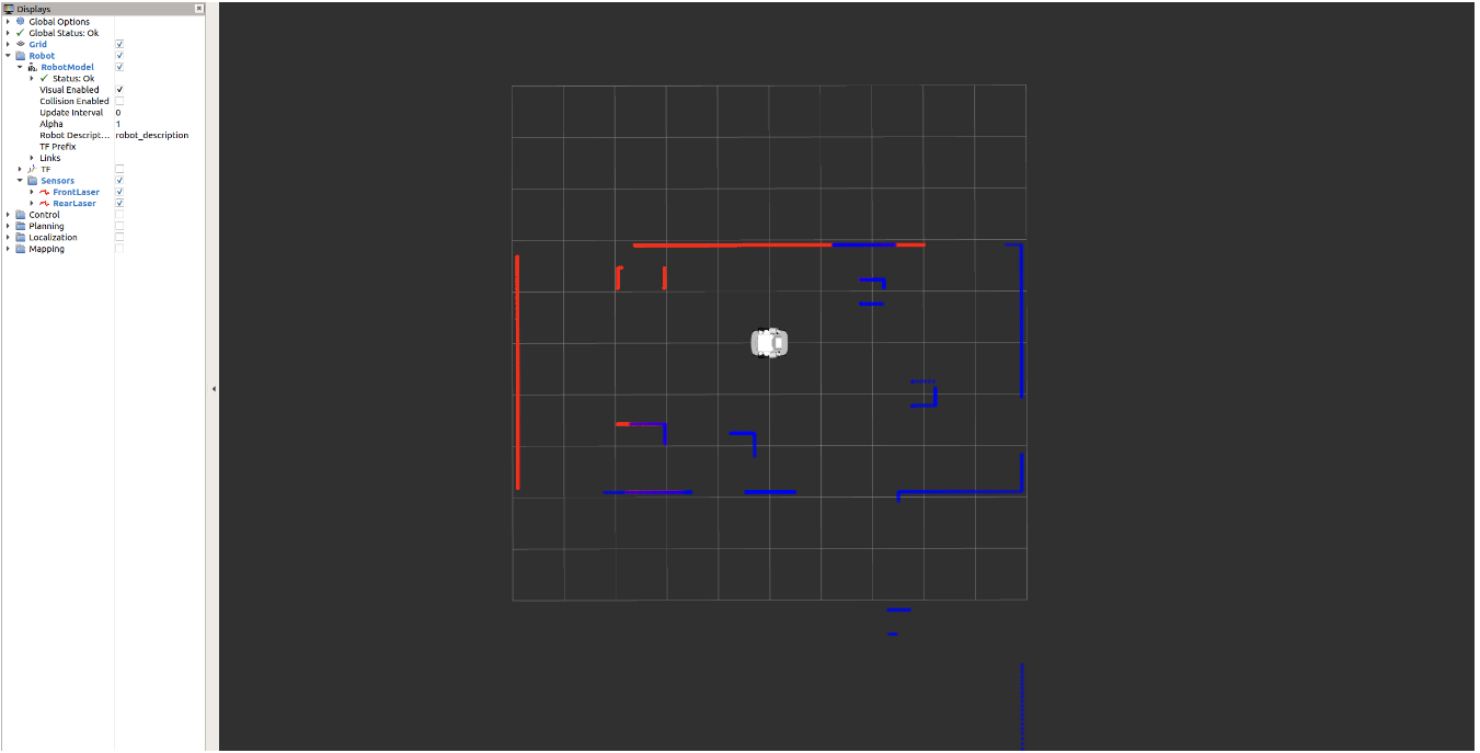
Figure: Visualization of the laser range-finder
13 Base motions
13.1 Overview
This section explains the different ways to move the TIAGo OMNI Base. The mobile base is based on an omnidirectional drive, which means that a linear and an angular velocity can be set, as shown in Head_parts. First, the motion triggers implemented in the joystick will be exposed, then the underlying ROS API to access the base controller will be presented.
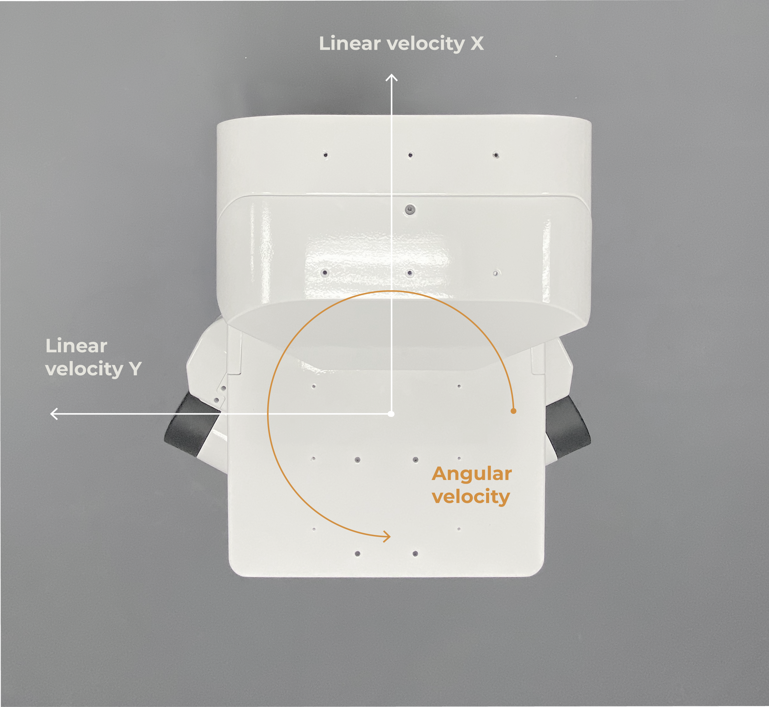
Figure: Mobile base velocities that can be commanded
13.2 Base motion joystick triggers
Firstly, the D-tab of your Logitech Controller joystick must be switched ON in order to activate the following functions.
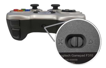
Figure: D-tab switched ON
In order to start moving the base with the joystick, priority has to be given to this peripheral. In order to gain priority with the joystick, just press the button shown in the figure below. Release the priority by pressing the same button.
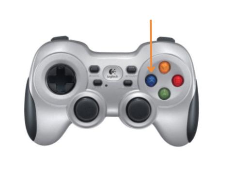
Figure: Taking priority with the joystick by pressing x
13.2.1 Forward/backward motion
To move the base forward, use the left analog stick, as shown in the figure below:
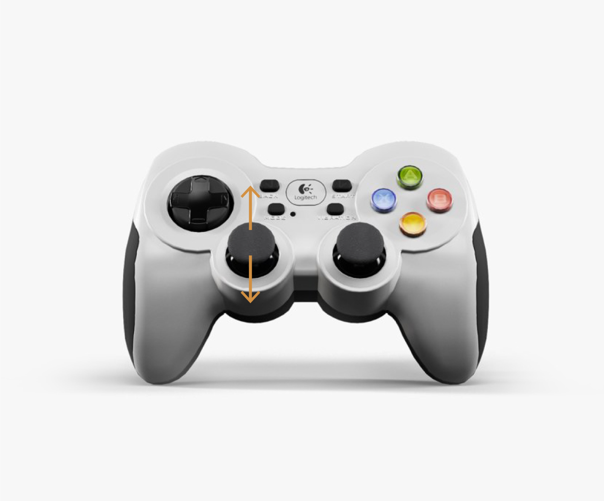
Figure: Base linear motion with the joystick
13.2.2 Lateral motion
To move the base laterally, use the left analog stick, as shown in the figure below:
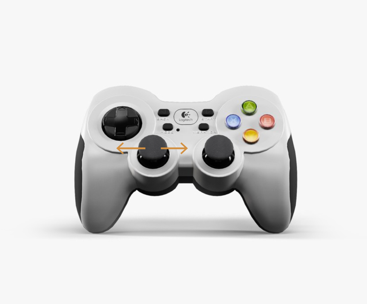
Figure: Base lateral motion with the joystick
13.2.3 Rotational motion
In order to make the base rotate on its Z axis, the right analog stick has to be operated, as shown in the figure below:
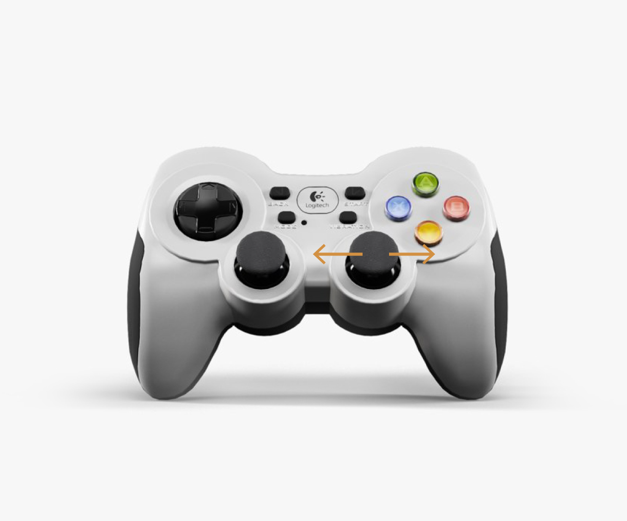
Figure: Base Rotational motion with the joystick
13.2.4 Changing the speed of the base
The default linear and rotation speed of the base can be changed with the following button combinations: Press and hold the LB+RB buttons along with the Y button to gradually increase the speed.
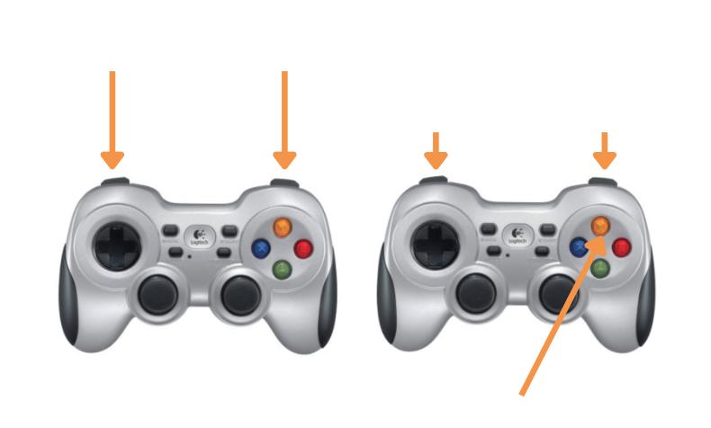
Figure: Joystick button combinations to increase speed
Press and hold the LB+RB buttons along with the A button to gradually decrease the speed
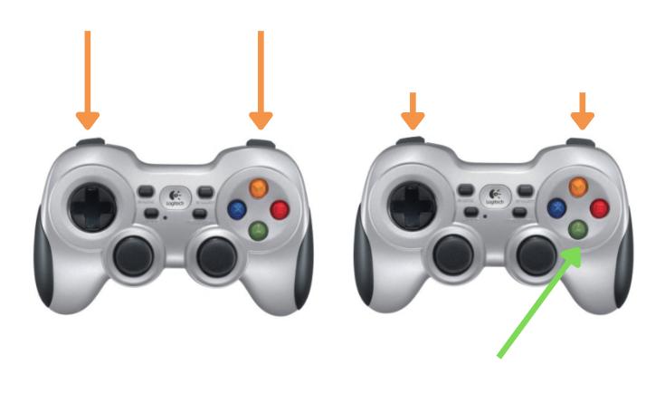
Figure: Joystick button combinations to decrease speed
13.3 Mobile base control ROS API
At user level, linear and rotational speeds can be sent to the mobile base controller using the following topic:
/mobile_base_controller/cmd_vel (geometry_msgs/Twist)
The given linear and angular velocities are internally translated to the required angular velocities of each of the four drive wheels.
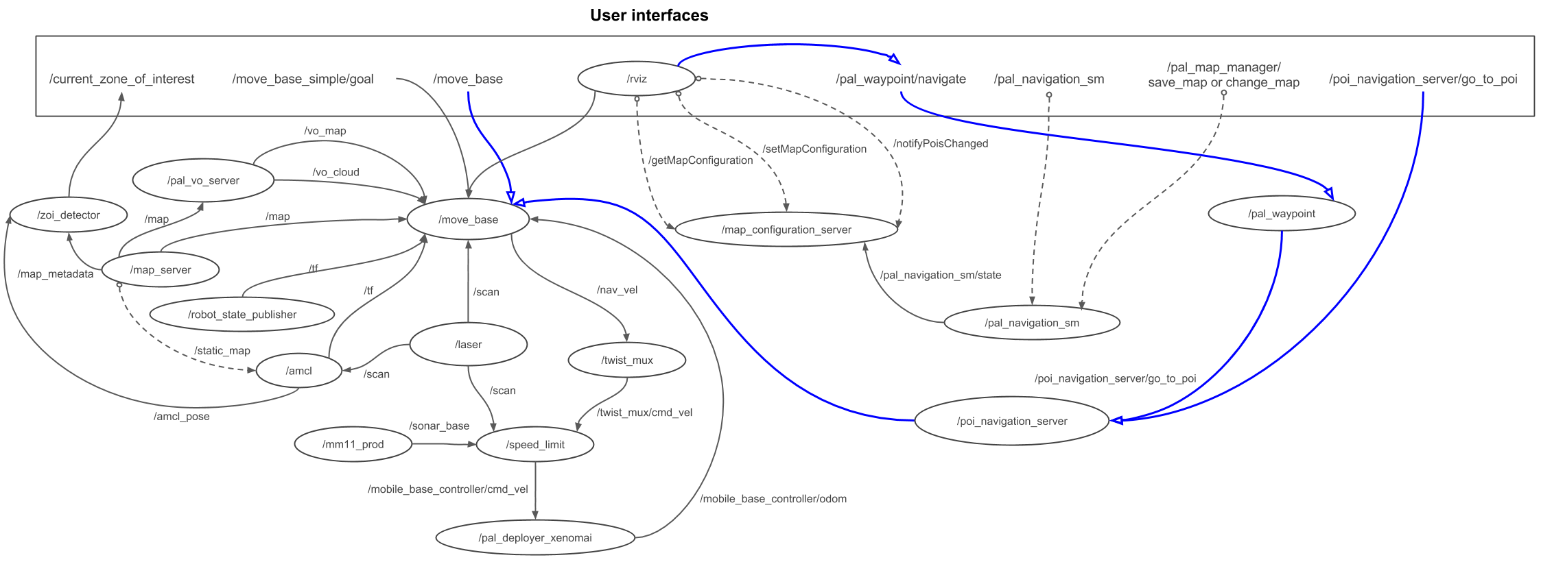
13.4 Mobile base control diagram
Different ROS nodes publish velocity commands to the mobile base
controller through the /mobile_base_controller/cmd_vel topic. In
figure below, the default nodes
trying to gain control of the mobile base are shown. From one side,
there are velocities triggered from the joystick and from the other
side, there are commands from the move_base node, which is used by
the navigation pipeline that is presented in
section Navigation.
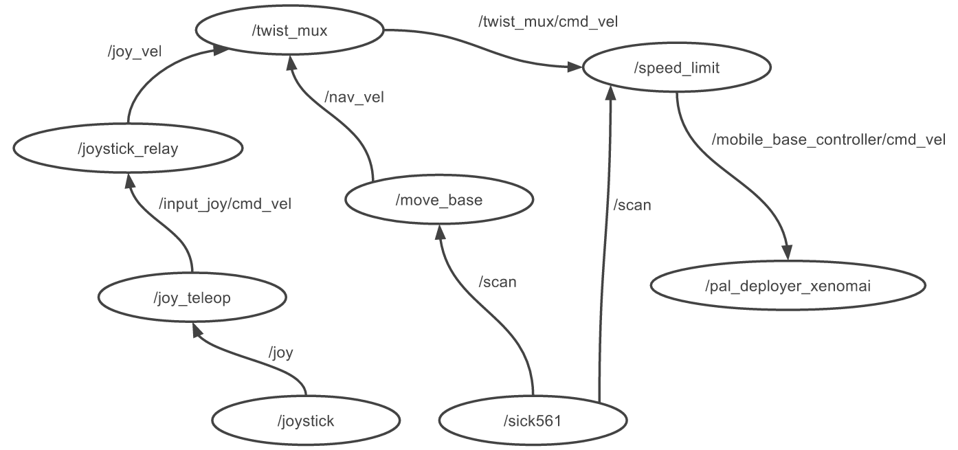
Figure: Mobile base control diagram
15 Dock station
15.1 Overview
Depending on the version acquired, your TIAGo OMNI Base may include a dock station that allows the robot to recharge itself automatically. This section will describe the components of the dock station and how to use integrate it with your algorithms.
15.2 The Dock Station Hardware
The dock is composed of a metal structure containing a pattern detected by TIAGo ’s LIDAR sensor, a connection to the external charger and the power contacts that will transmit energy to the robot, as shown in Figure: The dock station he dock also has tabs that can be screwed to the floor or wall to fix it in place, although this is not required. It is important to emphasize that although the charger possesses several security protections, the user should not touch or meddle with the power contacts, for safety reasons.
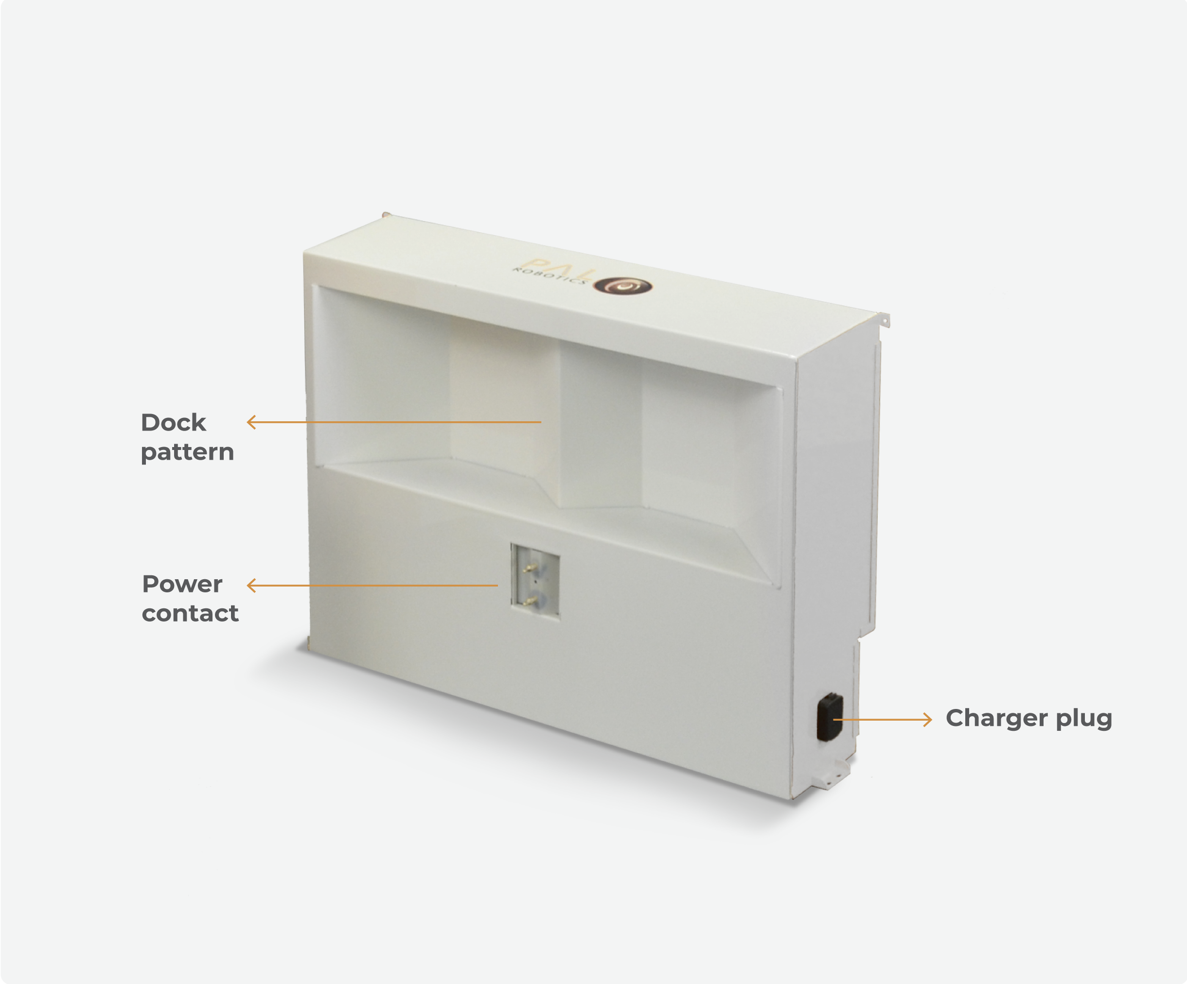
Figure: The dock station
15.3 Installation
The dock station should be preferably mounted against a hard surface, to avoid the robot displacing it while doing a docking manoeuvre. The power charger must be plugged in the respective plug. The user must also assure that no objects are present in the dock surroundings, that could interfere with the docking manoeuvre.
15.4 Docking Algorithm
When the robot is asked to go to the dock station, it activates two services in parallel. The first is responsable for the pattern detection, while the second performs the servoing to reach the power contacts: - pattern detector: the robot is capable of detecting the pattern up to 1 meters from the LIDAR sensor and with an orientation angle of ± 10º. - servoing manoeuvre: it comprises two steps, where first the robot aligns itself with the power contacts and, secondly, advances until the contact is made or a timeout occurs (in the case the dock station is not powered, or the contact fails for example).
The figure below illustrates the requirements for the docking maneouvre.
Once the robot is docked, it will block most velocity commands sent to the base, in order to avoid manoeuvres that could possibly damage the robot or the dock station. There are only two ways of moving the robot after is it docked: by doing an undock manoeuvre, or using the gamepad, which can override all velocity commands.
WARNING: It is the sole responsability of the user to operate safely the robot with the gamepad after the robot has reached the dock station.
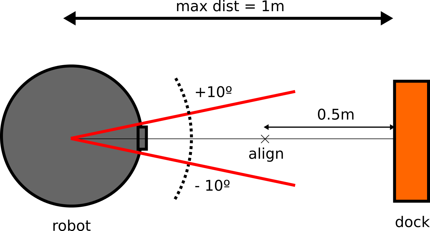
Figure: The docking specifications
15.4.1 Dock/Undock code example
Finally, the user can interface with the action servers directly by code, in either Python or C++. There is plenty examples of the usage of action clients in ROS Wiki. Bellow there is a very simple example in Python code, that connects and sends a goal to the /go_and_dock server. Note that the field goal.use_current_pose (line 19) is set to False, as in the previous example.
1. #!  / usr/bin / env python
2. import rospy
3. import rospkg
4. import  actionlib
5.
6. from dock_charge_sm_msgs.msg import GoAndDockAction, GoAndDockGoal
7. from std_msgs.msg import Bool
8.
9. class  SimpleDock():
10.    def  __init__(self) :
11.
12.       rospy.init_node('simple_dock')
13.       self.dock_checker_sub = rospy.Subscriber("/power/is_docked", Bool, self.is_docked_cb)
14.       self.is_docked = False
15.
16.    def go_and_dock_client(self):
17.
18.       goal = GoAndDockGoal()
19.       goal.use_current_pose = True
20.       self.dock_client  =  actionlib.SimpleActionClient("go_and_dock", GoAndDockAction)
21.       self.dock_client.wait_for_server()
22.       self.dock_client.send_goal(goal)
23.       rospy.loginfo("goalsenttogoanddockserver")
24.
25.    def is_docked_cb(self, is_docked):
26.       if(is_docked.data):
27.          self.dock_checker_sub.unregister()
28.          rospy.loginfo("simpledocker:therobotisdocked!")
29.          quit()
30.
31. if  __name__ == '__main__':
32.     try:
33.        sd = SimpleDock()
34.        sd.go_and_dock_client()
35.        rospy.spin ()
36.     except rospy.ROSInterruptException:
37.        print ( "programinterruptedbeforecompletion")
16 Simulation
16.1 Overview
When installing a development computer, as explained in develop-comp, the user can run Gazebo simulations of TIAGo OMNI Base.
Three different simulation worlds are provided with TIAGo OMNI Base, which are described in the following subsections.
16.1.1 Empty world
This is the default world that is loaded when the simulation is launched. The robot is spawned in an empty world with no objects, as shown in Figure: Empty world simulated in Gazebo. In order to launch the simulation, the following instruction needs to be executed in a terminal:
source /opt/pal/gallium/setup.bash
roslaunch omni_base_0_gazebo omni_base_gazebo.launch world:=empty
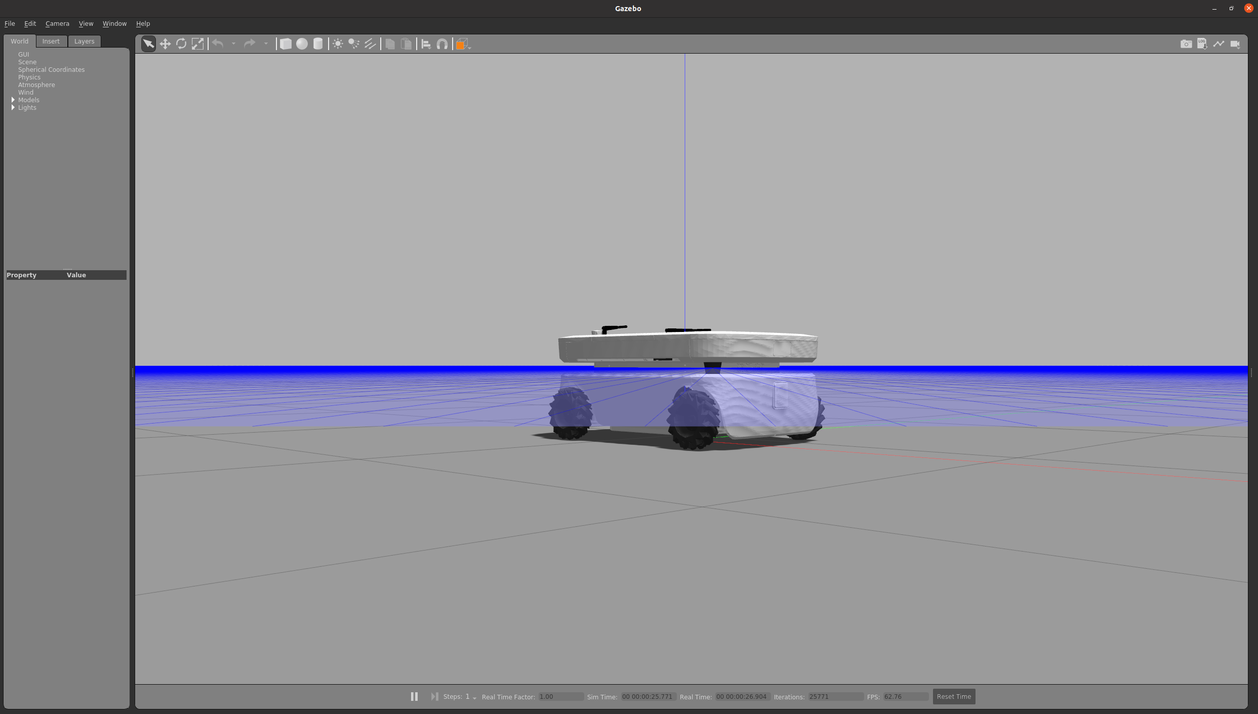
Figure: Empty world simulated in Gazebo
16.1.2 Office world
The simple office world shown in Figure: Small office world simulated in Gazebo can be simulated with the following instruction:
source /opt/pal/gallium/setup.bash
roslaunch omni_base_0_gazebo omni_base_gazebo.launch world:=small_office
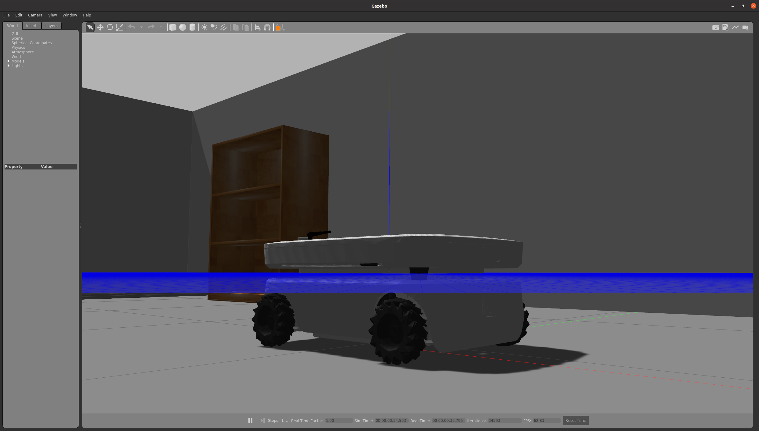
Figure: Small office world simulated in Gazebo


