1 TIAGo++ handbook
2 Package contents
2.1 Overview
This section includes a list of items and accessories that come with TIAGo++. Make sure they’re all present:
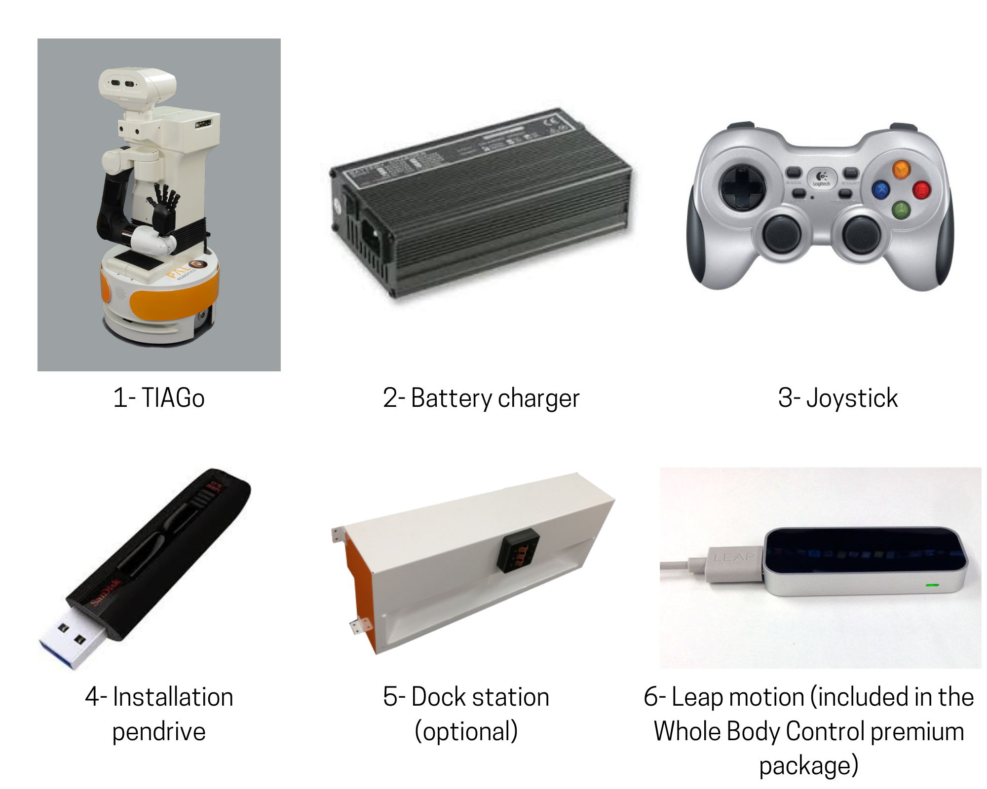
Figure: Components inside transportation box
3 Specifications
3.1 Robot overview
TIAGo++ ’s main parts are depicted in figure below, and its main specifications are summarized in table below:
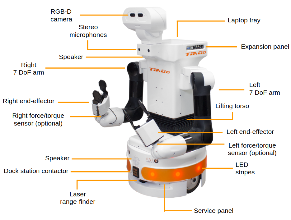
Figure: TIAGo++ ’s main components
Robot’s main specifications:
Height |
110 – 145 cm |
Weight |
72 Kg |
Base footprint |
Ø 54 cm |
Mobile base |
2 |
Torso lift |
1 |
Arm |
4 |
Wrist |
3 |
Head |
2 |
Hey5 hand |
19 (3 actuated) |
PAL gripper |
2 |
Drive system |
Differential |
Max speed |
1 m/s |
Lift stroke |
35 cm |
Payload |
2 Kg |
Reach |
87 cm |
Battery |
36 V, 20 Ah |
Base |
Laser range-finder, Sonars, IMU |
Torso |
Stereo microphones |
Arm |
Motors current feedback |
Wrist |
Force/Torque |
Head |
RGB-D camera |
3.2 Mobile base
TIAGo++’s mobile base is provided with a differential drive mechanism and contains an onboard computer, batteries, power connector, laser-range finder, three rear sonars, a user panel, a service panel and two WiFi networks to ensure wireless connectivity. Furthermore, the version of TIAGo with a docking station has a charging plate on the front
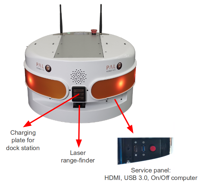
Figure: Mobile base front view
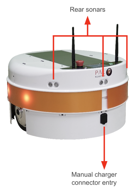
Figure: Mobile base rear view
3.2.1 Onboard computer
The specifications of TIAGo ’s onboard computer depends on the configuration options you have ordered. The different possibilities are shown in table below:
Component |
Description |
|---|---|
CPU |
Intel i5 / i7 |
RAM |
8 / 16 GB |
Hard disk |
250 / 500 GB SSD |
Wi-Fi |
802.11 a/b/g/n/ac |
Bluetooth |
Smart 4.0 Smart Ready |
3.2.2 Battery
The specifications of the battery supplied with TIAGo++ are shown in table:
Type |
Li-Ion |
|---|---|
V_nominal |
36.0 V |
V_max |
42.0 V |
V_cutoff |
30.0 V |
Nominal capacity |
20 Ah |
Nominal energy |
720 Wh |
Max. continuous discharge current |
20 A |
Pulse discharge current |
60 A |
Max. charging current |
15 A |
Charging method |
CC/CV |
Weight |
7.5 kg |
TIAGo++ can be equipped with two batteries. In this case, the total Nominal capacity is 1440 Wh.
3.2.3 Power connector
TIAGo++ must be charged only with suplied charger. To insert the charger connector, open the lid located on the rear part.
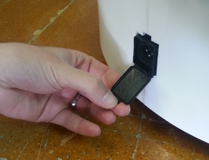
Figure: Charging connector entry
Connection Insert charging connector with metal lock facing up, push it until you hear a ’click’.
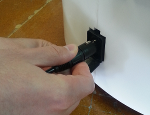
Figure: Charger connector insertion procedure
Disconnection Once charge is completed, connector can be removed. In order to do so, press metal lock and pull firmly the connector (see the figure below).
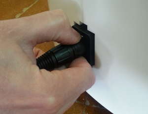
Figure: Charger connector removal procedure
3.2.4 Laser range-finder
The specifications of the laser on the front part of the mobile base depend on the configuration options you have ordered. The lasers supported are shown in table:
Manufacturer |
Hokuyo |
|---|---|
Model |
URG-04LX-UG01 |
Range |
0.02 - 5.6 m |
Frequency |
10 Hz |
Field of view |
180 degrees |
Step angle: |
0.36 degrees |
Manufacturer |
SICK |
|---|---|
Model |
TIM561-2050101 |
Range |
0.05 - 10 m |
Frequency |
15 Hz |
Field of view |
180 degrees |
Step angle: |
0.33 degrees |
Manufacturer |
SICK |
|---|---|
Model |
TIM571-2050101 |
Range |
0.05 - 25 m |
Frequency |
15 Hz |
Field of view |
180 degrees |
Step angle: |
0.33 degrees |
3.2.5 Sonars
The rear part of the mobile base has three ultrasound sensors, here referred to as sonars. One is centered and the other two are placed at 30º on the left and right. See table for the sonar’s specifications
Manufacturer |
Devantech |
|---|---|
Model |
SFR05 |
Frequency |
40 kHz |
Measure distance |
0.03 - 1 m |
3.2.6 IMU
The Inertial Measurement Unit is mounted at the center of the mobile base and may be used to monitor inertial forces and attitude. The specifications are presented in the table:
Manufacturer |
InvenSense |
|---|---|
Model |
MPU-6050 |
Gyroscope |
3-axis |
Accelerometer |
3-axis |
3.2.7 User panel
The user panel is on the top, rear part of TIAGo mobile base. It provides the buttons to power up and shutdown the robot, and a screen to give visual feedback on the robot’s status. All the specific elements of the user panel are shown in the figure below and the description of each element is presented in teh table:
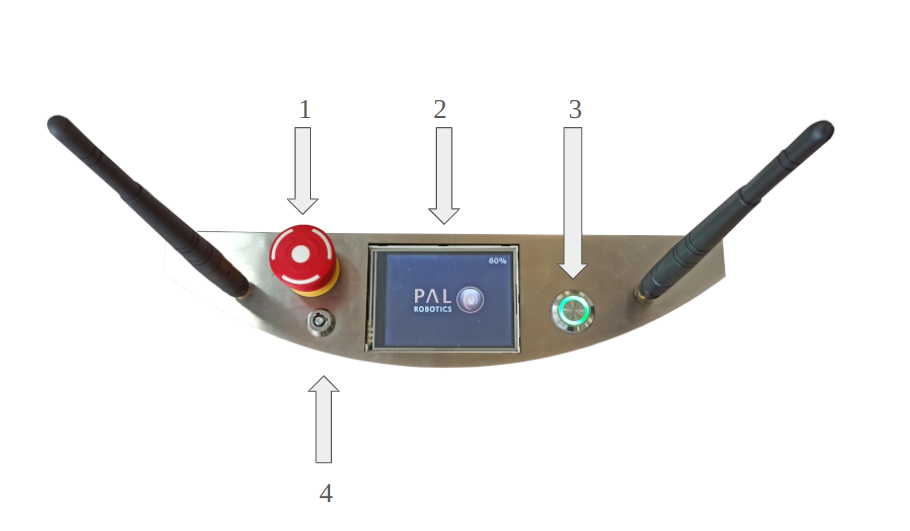
Figure: User Panel
Number |
Name / Short description |
|---|---|
1 |
Emergency stop |
2 |
Information display |
3 |
On / Off button |
4 |
Electric switch |
Electric switch The electric switch is the main power control switch. Before turning TIAGo ON make sure first that this switch is ON, i.e. its red light indicator is ON. On the other hand, when TIAGo is not going to be used for a long period, please press the switch so that its red light indicator turns OFF. Note that this switch should not be turned OFF before using the On/Off button to turn OFF the onboard computer of the robot. Turning OFF this switch will cut instantaneously the power supply to all the robot components, including the onboard computer. Do not use this switch as emergency stop. For the emergency stop please refer to the next section.
Emergency stop When pushed, motors are stopped and disconnected. Green indicator will blink fast in order to notify the emergency state.
To start the normal behaviour again, a two step validation must be executed: emergency button must be released rotating clockwise, and then On/On button must be pressed for 1 second. The green light will change to fixed state.
Information display 320x240 Color TFT display that shows battery level on the top-right corner.
On / Off button Standby control button. It is a push button with a green light to indicate the current system status.
Light |
State |
Name / Short description |
|---|---|---|
Off |
Fixed |
Standby |
On |
Fixed |
Running |
On |
Slow-Blink |
System in process of shutdown |
On |
Fast-Blink |
Emergency state |
After main power is connected, i.e. electric switch is ON (see Figure: User Panel), user must press this button during 1 second in order to start the TIAGo.
To set again the system in standby mode when is running, press again the button. The green light will blink slowly during shut down procedure and light-off when standby mode reached.
3.2.8 Service panel
It is possible to access the service panel by removing the cover behind the laser (see Figure: Service panel).
This service panel gives access to video, usb and on/off button of the robot’s computer. It can be used for reinstallation or debug propouses.
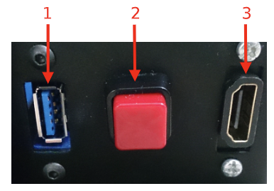
Figure: Service panel
Number |
Name / Short description |
|---|---|
1 |
USB 3.0 |
2 |
On/Off button computer |
3 |
HDMI (not in TIAGo Lite) |
3.2.9 Connectivity
TIAGo is equipped with a dual band Wireless 802.11b/g/n/ac interface, plus bluetooth 4.0 and a WiFi antenna. When the WiFi interface is configured as access point, it has a 802.11g interface.
There are two Gigabit Ethernet ports, ports 2 and 3 in the expansion panel figure, that can be used to connect to the robot’s internal network. For this network, the IP address range 10.68.0.0/24 has been reserved. The IP addresses used in the building network MUST not use this range because it can interfere with the robot’s services.
3.3 Torso
TIAGo++ ’s torso is the structure that supports the robot’s arm and head, and is equipped with an internal lifter mechanism which allows the user to change the height of the robot. Furthermore, it featuresan expansion panel and a laptop tray.
3.3.1 Lifter
The lifter mechanism is placed underneath the industrial bellows, shown in Figure: Industrial bellows of the lifting torso. The lifter is able to move at 50 mm/s and has a stroke of 350 mm. The minimum and maximum height of the robot is shown in Figure: Height range of the robot.
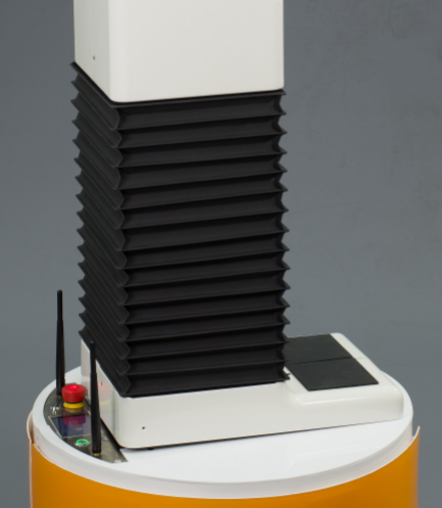
Figure: Industrial bellows of the lifting torso
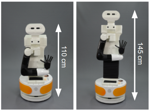
Figure: Height range of the robot
3.3.2 Expansion Panel
The expansion panel is located on the top left part of the torso and the connectors exposed are shown in figure below and specified in the table.
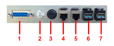
Figure: Expansion panel
Number |
Name / Short description |
|---|---|
1 |
CAN Service connector |
2 |
Mini-Fit Power supply 12 V and 5 A |
3 |
Fuse 5 A |
4 |
GigE port |
5 |
GigE port |
6 |
USB 2.0 port |
7 |
USB 3.0 port |
The CAN service connector is reserved for maintenance purposes and shall not be used.
3.3.3 Laptop tray
The laptop tray is the flat surface on top of the torso just behind the robot’s head, see Figure: Laptop tray dimensions. It has mounting points to add new equipment, supporting to 5 kg, or it can be used to place a laptop in order to work in place with the robot making use of the WiFi connectivityor using one of the ethernet ports in the expansion panel.
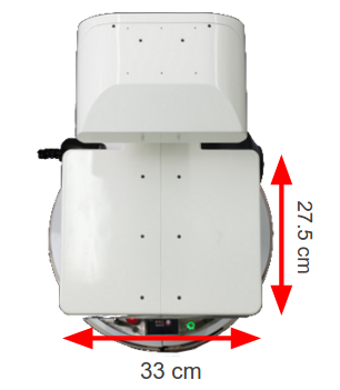
Figure: Laptop tray dimensions
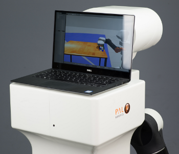
Figure: Laptop placed on the rear tray of the robot
3.4 Arm
TIAGo++’s arm is composed of four M90 modules and one 3 DoF wrist, M3D, as shown in figure below. The main specifications of the arm and wrist are shown in table:
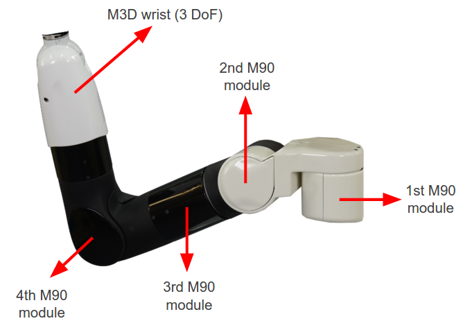
Figure: Arm components
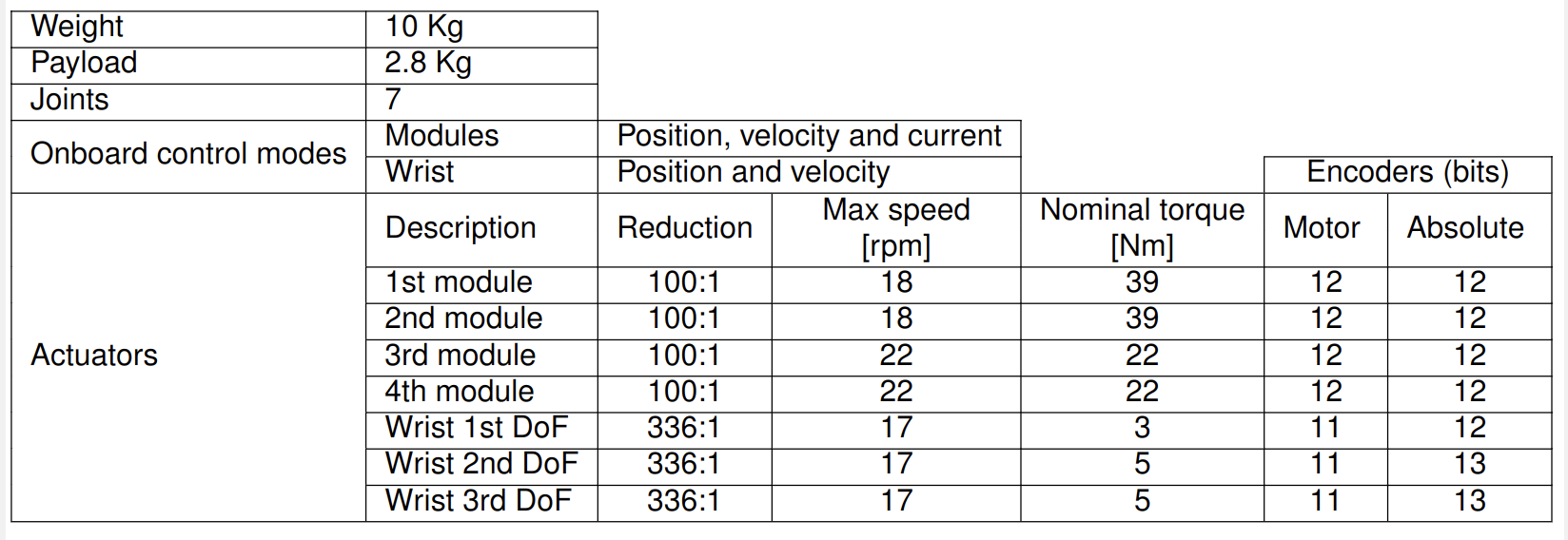
Figure: Arm and wrist specifications
3.5 Force/Torque sensor
The Force/Torque sensor integrated on the end-point of the wrist is an ATI mini45, see figure below. The mainspecifications of the sensor are summarized in the table below.
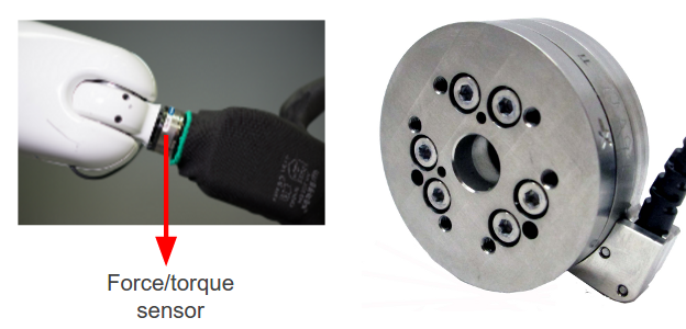
Figure: Force/torque sensor placement and close view
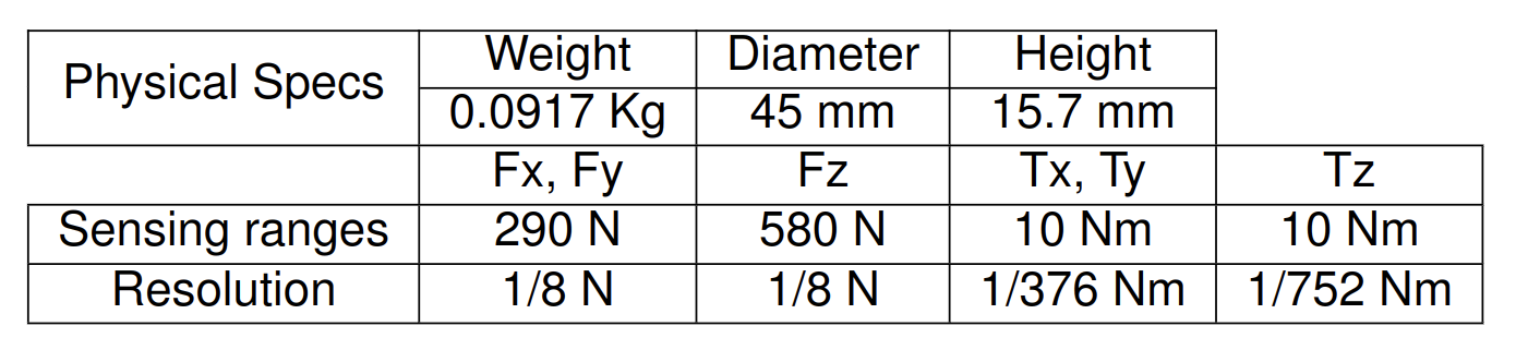
Main specifications of the force/torque sensor
3.6 End-effector
TIAGo++ ’s end-effector is one of the modular features of the robot. TIAGo++ can be used with six inter-changeable end-effectors: the Hey5 hand, the PAL parallel gripper, the Schunk WSG32 industrial gripper, the Robotiq 2F-85 gripper, the Robotiq-2F-140 gripper and the Robotiq EPick vacuum gripper.
Warning
Since September 2019 the Schunk WSG32 gripper is no longer available as the manufacturer has discountinued this product. Documentation about this end-effector is kept in this handbook as reference for customers already owning it.
3.6.1 Hey5 hand
The Hey5 hand is shown in the figure below. The main specifications of this underactuated, self-contained hand are summarized in the table.
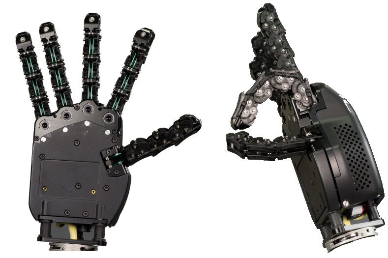
Figure: Hey5 hand
Weight |
720 g |
Payload |
1 Kg |
Joints |
19 |
Description |
Max speed [rpm] |
Max troque [Nm] |
|---|---|---|
Thumb |
32 |
0.23 |
Index |
32 |
0.23 |
Middle+right+little |
34 |
0.45 |
Credits and attribution
The Hey5 hand has been developed by PAL Robotics Inc., with contributions from QBrobotics srl.
The Hey5 hand is a derivative of the Pisa/IIT SoftHand open source project by M. G. Catalano, G. Grioli, E. Farnioli, A. Serio, C. Piazza and A. Bicchi.
The Pisa/IIT SoftHand project is distributed under Creative Commons Attribution 4.0 International License and is available at NaturalMachineMotionInitiative.com.
3.6.2 PAL gripper
The PAL parallel gripper is shown in figure below. The gripper contains two motors, each controlling one of the fingers. Each finger has a linear range of 4 cm.
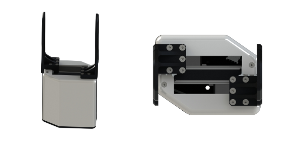
Figure: PAL gripper
Weight |
800 g |
Payload |
2 Kg |
interchangeable fingers |
Yes |
Description |
Reduction |
Max speed [rpm] |
Max troque [Nm] |
Absolute encoder |
|---|---|---|---|---|
Left finger |
193:1 |
55 |
2.5 |
12 bits |
Right finger |
193:1 |
55 |
2.5 |
12 bits |
3.6.3 Robotiq 2F-85/140 gripper
The adaptative robotiq gripper 2F-85 and 2F-140 are shown in the figure below. Their respective specifications canbe found in figure
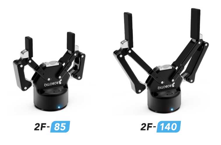
Figure: Robotiq 2F-85/140 grippers
Model |
2F-85 |
2F-140 |
Weight |
900 g |
1000 g |
Form-fit grip payload |
5 kg |
2.5 kg |
Gripper size |
85 mm |
140 mm |
Grip force |
20 to 235 N |
10 to 125 N |
Closing speed |
20 to 150 mm/s |
30 to 250 mm/s |
Note
Since the arm without end effector has a maximum payload of 3 kg, the real payload of 2F-85 and 2F-140 are 2.1 kg and 2.0 kg respectively.
The gripper equilibrium line is the grasping region that separates the encompassing grasp from the parallel grasp. When grasping an object close enough to the inside (palm) of the gripper, the encompassing grasp will occur (unless the object size or shape is not adequate) and the fingers will close around the object.
If grasped above the equilibrium line, the same object will be picked up in a parallel grasp by the fingertips and the fingers will close with a parallel motion. The figure below shows the encompassing grasp region, the equilibrium line, and the parallel grasp region on the 2-Finger Adaptive Gripper.
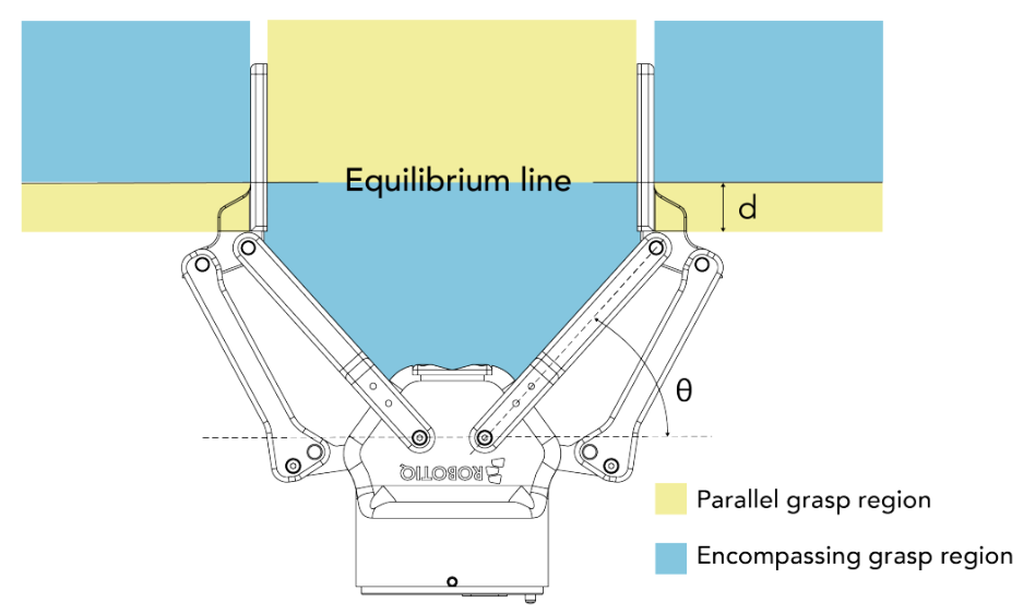
Figure: Robotiq 2F-85/140 gripper equilibrium line
3.6.4 Robotiq EPick Vacuum gripper
The Robotiq EPick vacuum gripper is a gripper shown in the figure below. It uses a suction cup to create a vac- uum to grasp an object, without an external air supply, making it suitable for mobile robots. The mechanical specifications are listed in table below.
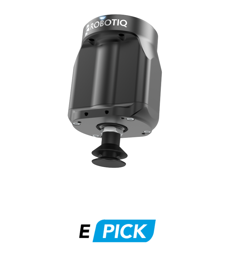
Figure: Robotiq 2F-85/140 gripper equilibrium line
Model |
EPick vacuum gripper |
Energy source |
Electricity |
Weight |
820 g |
Payload |
2 kg |
Maximum vacuum level |
80 % |
Maximum vacuum flow |
12 L/min |
Opertating ambient temperature |
5 to 40 °C |
3.7 Head
TIAGo++’s head is equipped with a pan-tilt mechanism, i.e. 2 DoF, and is equipped with stereo microphones, a speaker and an RGB-D camera. Furthermore, on top of the head there is a flat surface with mounting points to allow the user to add new sensors or equipment. Note that the head has a payload of 0.5 kg when adding new equipment. The figure below shows the location of each component and the two joints of the pan-tilt mechanism.
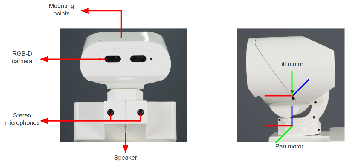
Figure: Head parts and components
3.7.1 Pan-tilt mechanism
Head pan-tilt main specifications:
Description |
Reduction |
Max speed [rpm] |
Max troque [Nm] |
Absolute encoder |
|---|---|---|---|---|
Pan motor |
200:1 |
63 |
6 |
12 bits |
Tilt motor |
200:1 |
63 |
6 |
12 bits |
3.7.2 Speaker
The speaker specified in the table is provided below the robot’s head.
Manufacturer |
VISATON |
Model |
FRS 5 |
Rated power |
5 W |
Max power |
8 W |
Nominal impedance Z |
8 Ohm |
Frequency response |
150-20000 Hz |
3.7.3 Stereo microphones
The Andrea SuperBeam Stereo Array Microphone is integrated just below the head of the robot. The specifications of the audio card are presented in the first table and the specifications of the Stereo Array Microphone are detailed in the second table:
Manufacturer |
Andrea Electronics |
Model |
SuperBeam Stereo Array Microphone |
Mic supply voltage |
1.4-5.0 VDC |
Supply bias resistor |
2.2k-39.9k Ohm |
Operating current (each channel) |
0.5 mA |
Output impedance at 1 kHz |
200 Ohm |
Max input sound level at 1 kHz, 3% THD |
115 dB |
Output signal level at THD < 3% @ 1 kHz |
24-120 mVrms |
Sensitivity at 1 kHz (0 dB = 1 V/Pa Vdc=1.6 V) |
-40 to -37 dBV |
Frequency response at 3 dB variation noise |
20 uVrms |
Operating temperature |
0-70C◦C |
Recommended operating distance |
30.5-122 cm |
Acoustic signal reduction at 1 kHz outside of 30◦beamform |
15-30 dB |
Noise reduction |
20-25 dB |
Manufacturer |
Andrea Electronics |
Model |
PureAudio USB-SA |
Supply voltage |
4.5 - 5.5 VDC |
Total power consumption |
120 mA |
A/D conversion resolution |
16 bit |
THD + N |
-84 dB |
Supply bias resistor |
2.2 kOhm @ 3.3 VDC |
Frequency response |
20-20000 Hz |
Input range |
0 - 1.25 Vrms |
Dynamic range |
95 dB |
Record gain range |
-6 to 33 dB |
3.7.4 RGB-D camera
TIAGo++’s head includes an RGB-D camera, specified below:
Manufacturer |
Orbbec |
Model |
Astra S |
Field of view |
60◦H, 49.5◦V, 73◦D |
Interface |
USB 2.0 |
Color stream modes |
QVGA 320x240 @ 30 fps, VGA 640x480 @ 30 fps, 1280x960 @ 10 fps |
Depth stream modes |
QVGA 320x240 @ 30 fps, VGA 640x480 @ 30 fps, 160x120 @ 30 fps |
Depth sensor range |
0.4 - 2 m |
3.8 Electrical parts and components
Neither TIAGo++ nor any of its electrical components or mechanical parts are connected to external ground. The chassis and all electromechanical components are physically isolated from the ground by the isolation rubber under its feet. Avoid touching any metal parts directly to prevent discharges and damage to TIAGo++’s electromechanical parts.
Electrical power supply and connectors
The power source supplied with TIAGo++ is compliant with the Directive on the restriction of the use of certain hazardous substances in electrical and electronic equipment 2002/95/EC (RoHS) and with the requirements of the applicable EC directives, according to the manufacturer. The power source is connected to the environment ground, whenever the supplied wire is used (Phase-Neutral-Earth).
4 Storage
4.1 Overview
This section contains information relating to the storage of TIAGo++.
4.2 Unboxing TIAGo++
This section explains how to unbox TIAGo++ safely. TIAGo++ is shipped with the flightcase shown in figure:
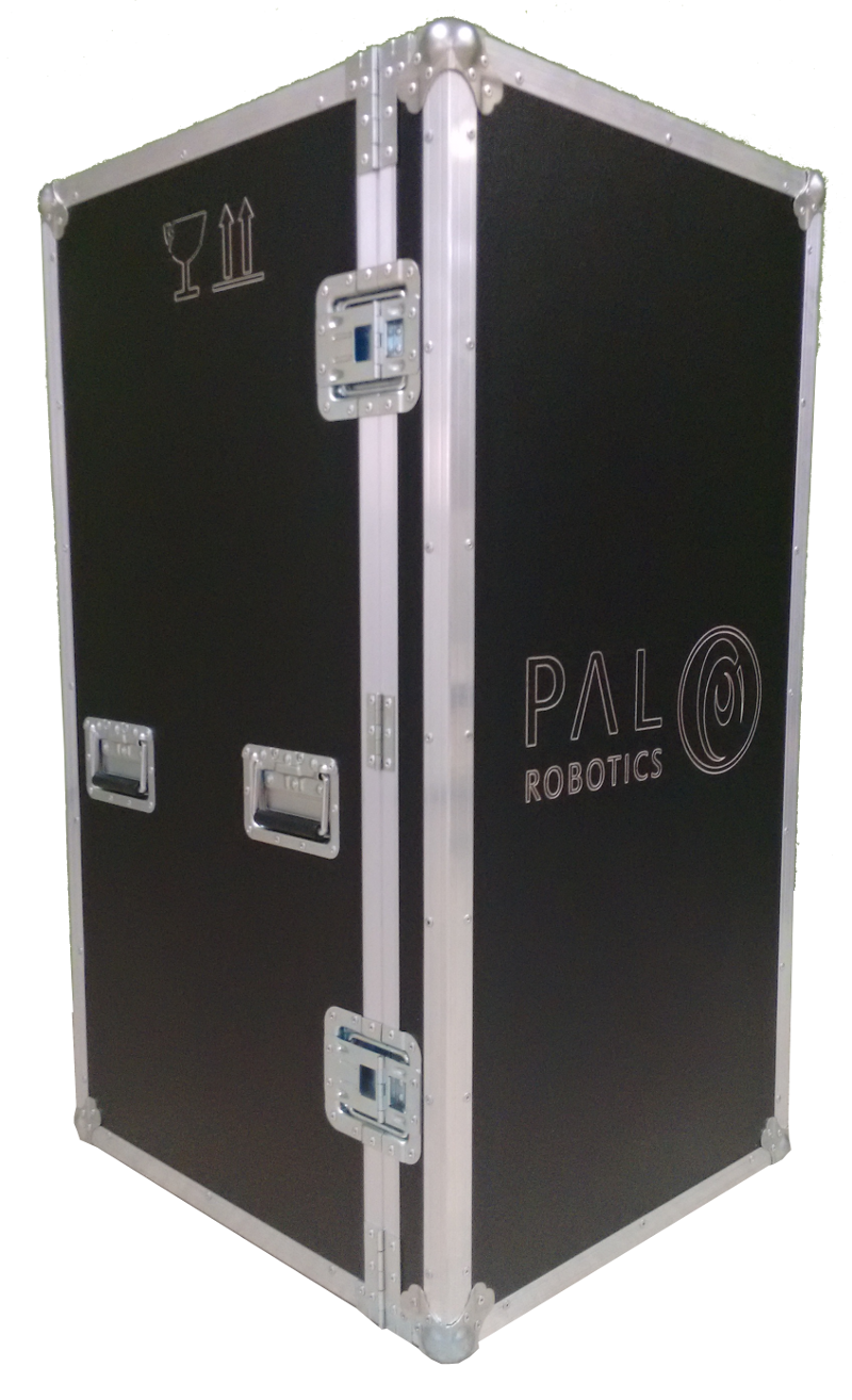
Figure: TIAGo++ flightcase
The flightcase MUST be always transported vertically to ensure the robot’s safety. In order to move the flightcase, pull the handle on the back, as shown in figure below. To place the flightcase in a given location use one of your feet to help you carefully set the flightcase in an upright position.
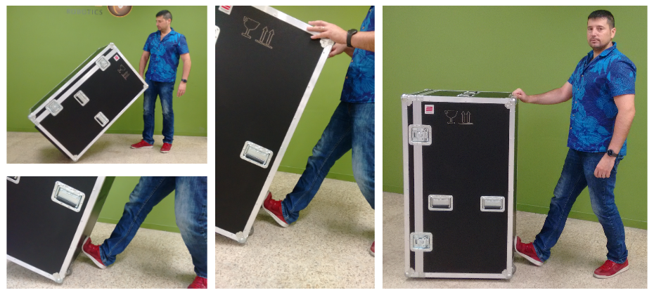
Figure: Moving the fligthcase
Open the door of the crate, see figure below a and unfold the ramp as shown in figure below b. Remove the foam wedges holding the mobile base as shown in figure below c. Finally, pull out TIAGo from the upper part of its torso back and, if necessary, from the bottom part of the shoulder, as shown in figure below d. Do not pull out the the robot from any part of the mobile base cover as damaged could be caused to you or to the robot.
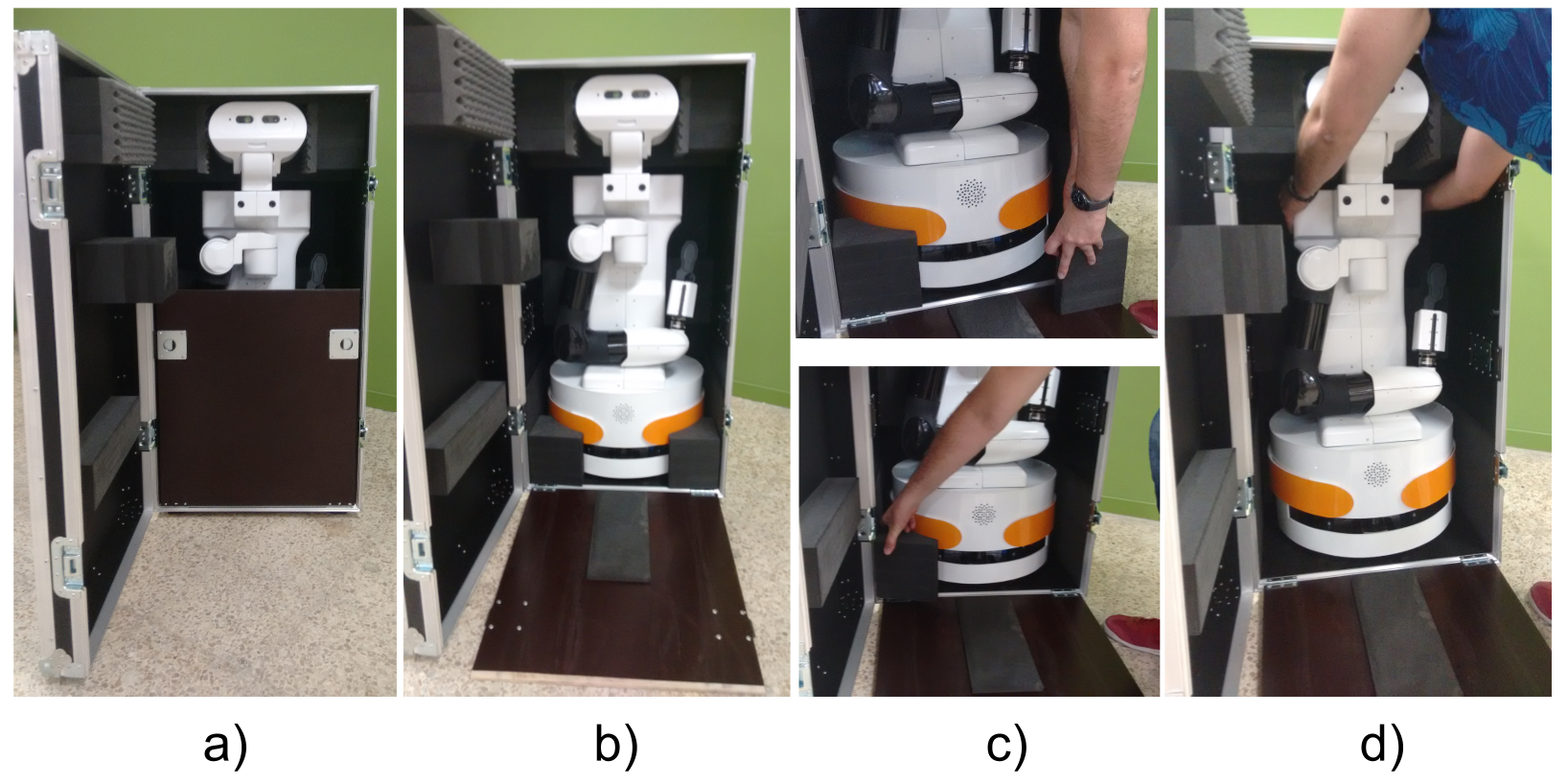
Figure: Unboxing procedure
5 Storage cautions
Always store TIAGo++ in a place where it will not be exposed to weather conditions.
The storage temperature range for TIAGo++ is between 0ºC ∼ +60ºC.
The storage temperature range for the batteries is between +10ºC ∼ +35ºC.
It is recommended to turn completly off (red power button is off) the TIAGo++ when the storage period exceeds two weeks.
It is recommended to charge the battery to 50% when storing it for more than two weeks.
Avoid the use or presence of water near TIAGo++.
Avoid any generation of dust close to TIAGo++.
Avoid the use or presence of magnetic devices or electromagneticfields near TIAGo++.
6 Introdution to safety
6.1 Overview
Safety is important when working with TIAGo++. This chapter provides an overview of safety issues, general usage guidelines to support safety, and describes some safety-related design features. Before operating the robot all users must read and understand this chapter!
6.2 Intended applications
It is important to clarify the intended usage of the robot before any kind of operation.
TIAGo++ is a robotics research and development platform meant to be operated in a controlled environment under supervision by trained staff at all time.
- The hardware and software of TIAGo++ allows to research and develop activities in the following areas:
Navigation and SLAM
Manipulation
Perception
Speech recognition
Human-robot interaction
6.3 Working environment and usage guidelines
The working temperatures are:
Robot: +10ºC ~ +35ºC
The space where TIAGo++ operates should have a flat floor and be free of hazards. Specifically, stair-ways and other drop offs can pose an extreme danger. Avoid sharp objects (such as knives), sources of fire, hazardous chemicals, or furniture that could be knocked over.
Maintain a safe environment:
The terrain for TIAGo++ usage must be capable of supporting the weight of the robot (see Specifications section). It must be horizontal and flat. Do not use any carpet, to avoid tripping over.
Make sure the robot has adequate space for any expected or unexpected operation.
Make sure the environment is free of objects that could pose a risk if knocked, hit, or otherwise affected by TIAGo++.
Make sure there are no cables or ropes that could be caught in the covers or wheels; these could pull other objects over.
Make sure no animals are near the robot.
Be aware of the location of emergency exits and make sure the robot cannot block them.
Do not operate the robot outdoors.
Keep TIAGo++ away from flames and other heat sources.
Do not allow the robot to come in contact with liquids.
Avoid dust in the room.
Avoid the use or presence of magnetic devices near the robot.
Apply extreme caution with children.
6.4 Battery manipulation
The following guidelines must be respected when handling the robot in order to prevent damage to the robot’s internal batteries.
Do not expose to fire.
Do not expose the battery to water or salt water, or allow the battery to get wet.
Do not open or modify the battery case.
Do not expose to ambient temperatures above 49ºC for over 24 hours.
Do not store in temperatures below -5ºC over seven days.
For long term storage (more than 1 month) charge the battery to 50%.
Do not use the TIAGo++’s batteries for other purposes.
Do not use other devices but the supplied charger to recharge the battery.
Do not drop the batteries.
If any damage or leakage is observed, stop using the battery.
7 Safety measures in practice
Warning
This Section presents important information that must be taken into consideration when using the robot. Read carefully the instructions to ensure the safety of the people on the surroundings and to prevent damages to the environment and to the robot. Follow these instructions everytime the robot is used.
7.1 Turning the robot on properly
Warning
The procedure described in this section requires to have a clearance of about 1.5 m in front of the robot and at each of its sides in order to execute the required movements safely.
When the robot is started the arms will be lying on the lateral sides of the mobile base. If the robot arms are left in such position after turning the robot on the heat from the arm motors may be transfered, after some time, to the paint of the robot’s base cover which may end up melting it and causing aesthetical damage to these covers. In order to prevent this follow the procedure depicted in Figure: Procedure to start moving the arm safely and here after explained:
Raise the torso to its maximum height using the joystick. In case the torso does not move either press the button Get out of collision in the Demos tab of the WebCommander, see the section 13 WebCommander, or run the following command line instruction:
export ROS_MASTER_URI=http://tiago-0c:11311
rosservice call /get_out_of_collision
Execute the Offer Both movement using, for instance, the Movements tab of the WebCommander
Exectute the Home motion in order to fold back the arms and the torso into a safe configuration where no contacts occur with the base of the robot.
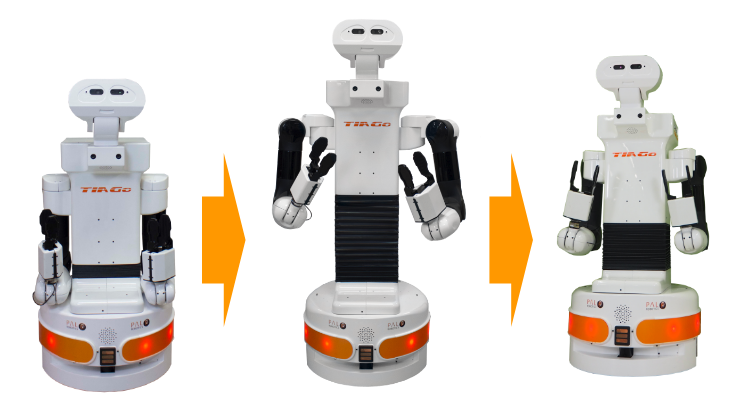
Figure: Procedure to start moving the arm safely
7.2 Shutting down the robot properly
Warning
The procedure described in this section when operating with TIAGo++ requires two people in order to be done properly.
Special care needs to be taken when shutting down or powering off the motors by using the emergency button. In order to avoid bumping the arms against the base of the robot or the floor, the following procedure must be followed, as depicted in figure below:
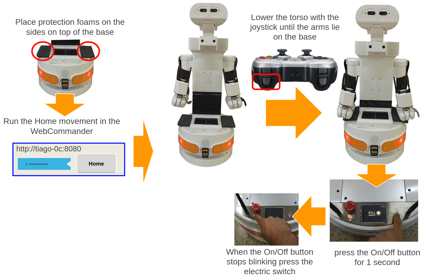
Figure: Shutdown procedure
7.3 Emergency stop
Warning
To safely operate with the emergency stop of TIAGo++ two people are recommended.
The emergency stop button can be found on the back of the robot between the power button and the battery level display. As the name implies, this button should only be used only in exceptional cases, when an immediate stop of the robot’s motors is required.
To activate the emergency stop, the user has to push the button. To deactivate the emergency stop, the button has to be rotated clockwise, according to the indications on the button, until it pops out.
Be careful using this emergency stop because the motors will be switched OFF and the arms will fall down, while the computer remains on.
After releasing the emergency stop button, the user has to re-start the robot by pressing the On/Off button until it stops blinking. After this operation, the robot’s status should be restored to that prior to pressing the emergency button in few seconds.
7.4 Measures to prevent falls
TIAGo++ has been designed to be statically stable, even when the arms are holding their maximum payload in their most extreme kinematic configuration. Nevertheless, some measures need to be respected in order to avoid the robot from tipping over.
7.4.1 Measure 1
Do not apply external downward forces to the arms when they are extended in the direction shown in figure below:
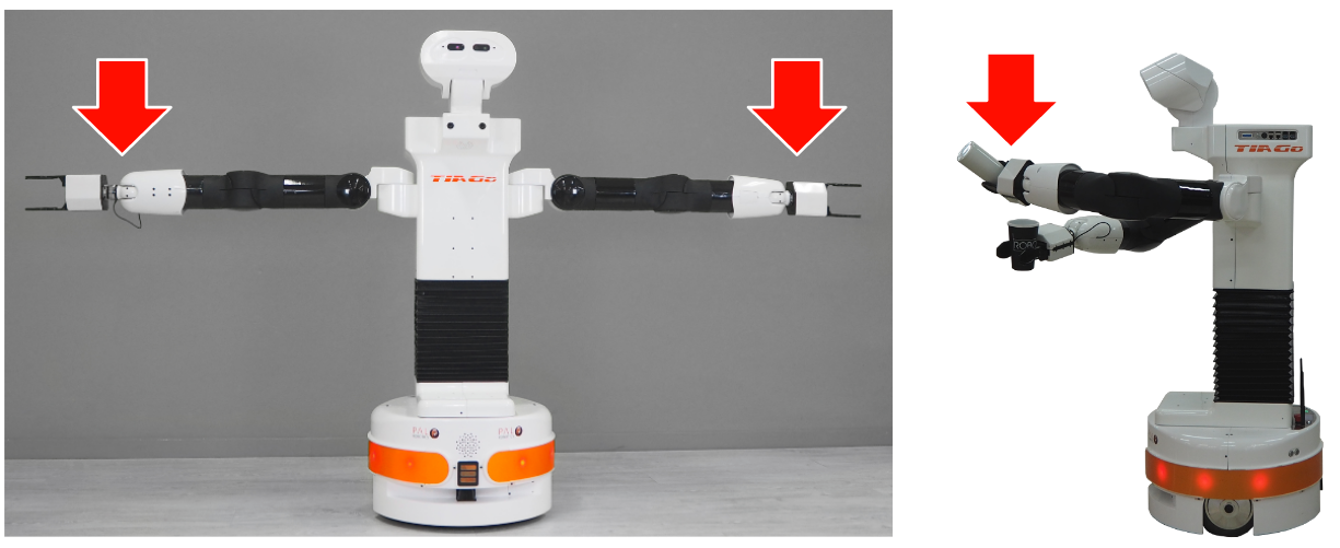
Figure: Fall prevention measure 1
7.4.2 Measure 2
Do not navigate when the arms are extended, especially when the torso is also extended, see figure below:
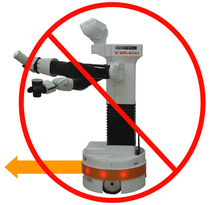
Figure: Fall prevention measure 2
7.4.3 Measure 3
TIAGo++ has been designed to navigate in flat floor conditions. Do not navigate on floors with unevenness higher than 5%, see figure below:
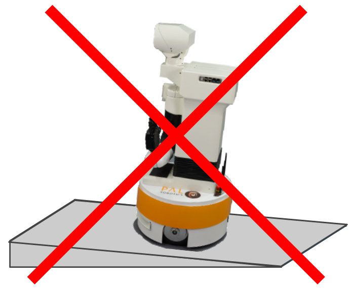
Figure: Navigation in ramps is not recommended
7.4.4 Measure 4
Avoid navigating close to downward stairs, as TIAGo++’s laser range-finder will not detect this situation and the robot may fall down the stairs.
7.4.5 Measure 5
In order to maintain safety, it is highly recommended to navigate with the arms folded and the torso at a low extension, like in the predefined Home configuration, see figure below. This pose provides the following advantages:
Reduces the robot’s footprint, lowering the probability that the arms collide with the environment
Ensures the robot’s stability as the center of mass is close to the center of the robot and it is kept low
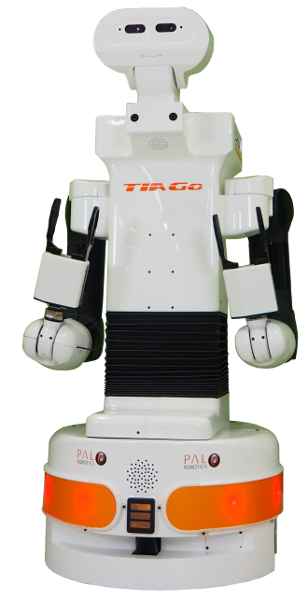
Figure: Fall prevention measure 4
7.5 Measures to prevent collisions
Most collisions occur when moving TIAGo++’s arms. It is important to take the following measures into account in order to minimize the risk of collisions.
7.5.1 Measure 1
Make sure that there are no obstacles in the robot’s surroundings when playing back a predefined motion or moving the joints of the arms. Provided that the maximum reach of the arm is 86 cm without the end-effector, a safe way to move the arms is to have a clearance around the robot of about 1.5 m.
7.5.2 Measure 2
Another active measure that could mitigate damage due to collisions is
the collision detector node. This is found in the startup extras tab
of the Web Commander. This is, in fact, an example of how to implement
safety using feedforward current control. When enabled, this node monitors
the current consumption of the seven joints of the arms. If a joint is
consuming more than a given threshold, it stops the motion. Note that when
this node is running, the arms will not be able to handle some heavy objects
as the extra payload could cause extra current consumption in some joints.
This would abort the specific motion. It is also worth noting that the gravity
compensation mode generates some noise in the current when changing from current
to position control. In such a case, if the collision detector is activated,
this can trigger the abortion of the motion.
This safety measure is not available when the Whole Body Control is running.
It is important to remark that this node should not be used as a final safety
measure. This is just an example and is not fully tested as such.
7.6 How to proceed when an arm collision occurs
Warning
As prevention measure, when doing movements with TIAGo++’s arms it is strongly recommended that there are two people overseeing the robot and ready to react in case of need of an emergency stop.
When any of the arms collide with the environment, see Figure: Example of arm collision onto a table, the motors of the arm will continue exerting force, which may cause potential damage to the environment or the arm covers. Serious damage to the motors will not occur, as they have integrated self-protection mechanisms to detect over-heating and overcurrent which switches them off automatically if necessary. Nevertheless, in order to minimize potential harm to the environment and to the robot, the following procedure should be undertaken, as depicted in Figure: How to proceed when a collision occurs:
Press the emergency button to power off the robot’s motors. The arms will fall down, so be ready to hold the wrists while the emergency button remains activated
Move the robot out of the collision by pushing the mobile base and pulling the arm to a safe place
Release the emergency button by rotating it clockwise according to the indications on the button until it pops out. When the On/Off button flashes, press it for 1 second
The power and control mode of the motors are restored and the robot is safe and operational
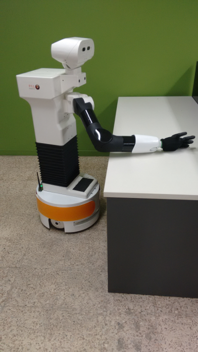
Figure: Example of arm collision onto a table
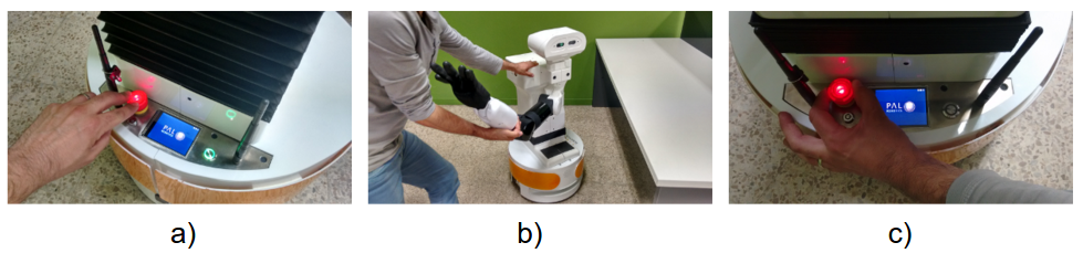
Figure: How to proceed when a collision occurs
7.7 Low battery shutdown
If the battery falls below a certain critical level, the current consumption is progressively reduced in order to make the arm fall down slowly and avoid any damage in the robot due to a blackout. Nevertheless, we recommend the user to avoid working when the battery is very low becuase when the arm falls down, even if slowly, it may collide with the environment.
7.8 Firefighting equipment
For correct use of TIAGo++ in a laboratory or location with safety conditions, it is recommended to have in place a C Class or ABC Class fire extinguisher (based on halogenated products), as these extinguishers are suitable for stifling an electrical fire.
If a fire occurs, please follow these instructions:
Call the firefighters.
Push the emergency stop button, as long as you can do so without any risk.
Only tackle a fire in its very early stages.
Always put your own and others’ safety first.
Upon discovering the fire, immediately raise an alarm.
Make sure the exit remains clear.
Fire extinguishers are only suitable for fighting a fire in its very early stages. Never tackle a fire if it is starting to spread or has spread to other items in the room, or if the room is filling with smoke.
If you cannot stop the fire or if the extinguisher runs out, get yourself and everyone else out of the building immediately, closing all doors behind you as you go. Then ensure the fire brigade are on their way.
7.9 Leakage
The battery is the only component of the robot that is able to leak. To avoid leakage of any substance from the battery, follow the instructions defined in section of 4 Storage, to ensure the battery is manipulated and used correctly
8 Robot Identification
The robot is identified by a physical label that can be found close to the power connector.
This label contains:
Business name and full address.
Designation of the machine.
Part Number (P.N.).
Year of construction.
Serial number (S.N.).

Figure: Identification label
9 Default network configuration
When shipped or when a fresh re-installation is performed, the robot is configured as an access point. The information about the robot’s network is provided in the table below. Note that the SSID ends with the serial number of the robot, i.e. in the given example the s/n is 0.
SSID |
tiago-0 |
Channel |
1 |
Mode key |
WPA-PSK |
Password |
|
Robot IP |
10.68.0.1 |
The address range 10.68.0.0-24 has been reserved. The robot computer name is tiago-Xc, where X is the
serial number without the “0s” on the left. The alias control is also defined in order to refer to the computer
name of the robot when connecting to it when it is set as access point or when using a direct connection, i.e.
an Ethernet cable between the robot and the development computer.
10 Software recovery
10.1 Overview
This section explains the System and Software reinstall procedure for TIAGo++.
10.2 Robot computer installation
To begin the installation process, plug a monitor and USB keyboard into the HDMI connector. See 3.2.8 Service panel section for information about the service panel.
BIOS configuration: Some options in the Control BIOS computer must be configured as follows:
Turn on the robot and press F2 repeatedly. Wait until the BIOS menu appears.
Enter Advance Mode by pressing F7.
- In the Advanced > CPU Configuration menu:
Set Intel Virtualization Technology to Disabled.
- In the Advanced > CPU Configuration > CPU Power Management Configuration menu:
Set Intel(R) SpeedStep (tm) to Disabled.
Set CPU C-states to Disabled.
- In the Boot > Boot Configuration menu:
Set Wait for ‘F1’ if Error to Disabled.
Go to Exit and select Save Changes & Reset.
Shut down the robot.
Installation: The installation is performed using the Software USB drive provided with TIAGo++.
Insert the Software USB drive.
Turn on the robot and press F2 repeatedly. Wait until the BIOS menu appears.
Enter the Boot Menu by pressing F8 and select the Software USB drive.
The Language menu will pop up. Select English.
The menu shown in Figure: System installation menu.
Select Install TIAGo++.
Select the keyboard layout by following the instructions.
10.3 Development computer installation
Hardware installation: Connect the computer to the electric plug, the mouse and the keyboard. Internet access is not required as the installation is self-contained.
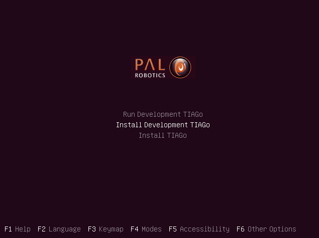
Figure: System installation menu
Software Installation: The installation is performed using the Software USB drive provided with TIAGo++.
Insert the Software USB drive.
Turn on the computer, access the BIOS and boot the Software USB drive.
The Language menu will pop up. Select English.
The menu shown in figure below:
Figure: System installation menu
Choose Run Development TIAGo++ if you wish to run the development computer without installing it or to install it in a specific partition. Using the Install Development TIAGo++ option will delete all partitions in the disk and automatically install the system in a new partition.
Select the keyboard layout by following the instructions.
11 TIAGo++ Robot’s Internal Computers
11.1 TIAGo++ LAN
The name of TIAGo++’s computer is tiago-0c, where 0 needs to be replaced by the serial number of your robot. For the sake of clarity, hereafter we will use tiago-0c to refer to TIAGo++’s computer name.
In order to connect ot the robot, use ssh as follows:
ssh pal@tiago-0c
11.2 File system
The TIAGo++ robot’s computer has a protection against power failures that could corrupt the filesystem.
These partitions are created:
/: This is an union partition, the disk is mounted in /ro directory as read-only and all the changes arestored in RAM. So, all the changes are not persistent between reboots.
/home: This partition is read-write. Changes are persistent between reboots.
/var/log: This partition is read-write. Changes are persistent between reboots.
In order to work with the filesystem as read-write do the following:
root@tiago-0c:~# rw
Remounting as rw...
Mounting /ro as read-write
Binding system files...
root@tiago-0c:~# chroot /ro
rw command remounts all the partitions as read-write. Then with a chroot to /ro we have the same system than the default but all writable. All the changes performed will be persistent.
In order to return to the previous state do the following:
root@tiago-0c:~# exit
root@tiago-0c:~# ro
Remount /ro as read only
Unbinding system files
First exit command returns from the chroot. Then the ro script remounts the partitions in the default way.
11.3 Internal DNS
The control computer has a DNS server that is used for the internal LAN of the TIAGo++ with the domain name reem-lan. This DNS server is used by all the computers connected to the LAN.
When a computer is added to the internal LAN (using the Ethernet connector, for example) it can be added to the internal DNS with the command addLocalDns:
root@tiago-0c:~# addLocalDns -h
-h        shows this help
-u DNSNAME  dns name to remove
Example: addLocalDns -u terminal
The same command can be used to modify the IP of a name: if the dnsname exists in the local DNS, the IP address is updated.
To remove names in the local DNS, exit the command delLocalDns:
root@tiago-0c:~# delLocalDns -h
-h          shows this help
-u DNSNAME  dns name to remove

Example: addLocalDns -u terminal
These additions and removals in the local DNS are not persistent between reboots.
11.4 NTP
Since big jumps in the local time can have undesired effects on the robot applications, NTP is setup when the robot starts and before the ROS master is initiated. If no synchronization was possible, for example if the NTP servers are offline, the NTP daemon is stopped after a timeout.
To setup ntp as client edit the etc/ntp/.conf file and add your desired ntp servers. You can use your own local
time servers or external ones, such as ntp.ubuntu.com. You can also try uncommenting the default servers already present.
For example, if the local time server is in 192.168.1.6 add the following to the configuration file.
server 192.168.1.6 iburst
Restart the ntp daemon to test your servers.
systemctl restart ntp.service
Run the ntpq -p command and check that at least one of the configured servers has a nonzero reach value and a nonzero offset value.
The corrected date can be consulted with the date command.
Once the desired configuration is working make sure to make the changes in /etc/ntp.conf persistant and reboot the robot.
If, on the contrary, you want the robot to act as the NTP server of your network, no changes are needed. The current ntp daemon already acts as server. You will only need to configure NTP for the clients.
To configure NTP on the rest of the clients, like the development PCs, run:
systemct1 status ntp.service
If the service is active follow the previous steps to configure the ntp daemon. Once again a private or public NTP server can be used. If, instead the robot is desired as server add this line to /etc/ntp.conf.
server tiago-0c iburst
If the service is not found then that means ntp is not installed. Either install it with apt-get install ntp or make use of Ubuntu’s default ntp client called timesyncd.
To configure timesyncd simply edit the /etc/systemd/timesyncd.conf file and set the proper NTP server.
Restart the timesyncd daemon.
systemctl restart systemd-timesyncd.service
Check the corrected date with the date command. The time update can take a few seconds.
11.5 System upgrade
For performing system upgrades connect to the robot, make sure you have Internet access and run the pal_upgrade command as root user.
This will install the latest TIAGo++ software available from the PAL repositories.
Reboot after upgrade is complete.
11.6 Firmware update
To update firmware, use the application described in section 11.5 System upgrade. Check for updates for the pal-ferrum-firmware-* packages and install them.
Before running the script, place the arm in a safe position with a support underneath it, as during the installation of the script, the arm can tumble.
Run the update_firmware.sh script, as shown below. The update will take a few minutes.
pal@tiago-0c:~# rosrun firmware_update_robot update_firmware.sh
Finally, shut it down completely, power off with the electric switch and then power up the robot, as described in 3.2.7 User panel.
11.7 Meltdown and Spectre vulnerabilities
Meltdown and Spectre exploit critical vulnerabilities in modern processors.
Fortunately the linux Kernel has been patched to mitigate these vulnerabilities, this mitigation comes at a slight performance cost.
PAL Robotics configuration does not interfere with mitigation, whenever the installed kernel provides mitigation, it is not disable by our software configuration.
Below we provide some guidelines to disable the mitigation in order to recover the lost performance, this is not recommended by PAL Robotics and it is done on the customer’s own risk.
On this website the different tunables for disabling mitigation controls are displayed.
These kernel flags must be applied to the GRUB_CMDLINE_LINUX in /etc/default/grub. After changing them, update-grub must be executed, and the computer must be rebooted.
These changes need to be made in the persistent partition, as indicated in 11.2 File system
Be extremely careful when performing these changes, since they can prevent the system from booting properly.
12 Development Computer
12.1 Overview
The operating system used in the SDE Development Computer is based on a Linux Ubuntu distribution. Any documentation related to this specific Linux distribution applies to SDE. This document only points out how the PAL SDE differs from standard Ubuntu.
12.2 Computer requirements
A computer with 8 CPU cores is recommended. A powerful graphics card with resolution of at least 1920x1080 pixels is recommended in order to have a better user experience when using visualization tools like rviz and the Gazebo simulator. The development computer ISO provides support for Nvidia cards. In case of upgrading the kernel of the development computer PAL Robotics cannot ensure proper support for other graphic cards.
12.3 Setting ROS environment
In order to use the ROS commands and packages provided in the development ISO the following command needs to be executed when opening a new console
# Pal distro environment variable
export PAL_DISTRO=gallium
export ROS_DISTRO=noetic
source /opt/pal/${PAL_DISTRO}/setup.bash
If you are using a ros2 distribution
# Pal distro environment variable
export PAL_DISTRO=alum
export ROS_DISTRO=humble
source /opt/pal/${PAL_DISTRO}/setup.bash
A good way to spare the execution of this command everytime is to append it at the /home/pal/.bashrc file.
12.4 ROS communication with the robot
When developing applications for robots based on ROS, it is typical to have the rosmater running on the
robot’s computer and the development computer running ROS nodes connected to the rosmaster of the
robot. This is achieved by setting in each terminal of the development computer running ROS nodes the following environment variable:
export ROS_MASTER_URI=http://tiago-0c:11311
Note that in order to successfully exchange ROS messages between different computers, each of them needs to be able to resolve the hostname of the others. This means that the robot computer needs to be able to resolve the hostname of any development computer and vice versa. Otherwise, ROS messages will not be properly exchanged and unexpected behavior will occur.
Do the following checks before starting to work with a development computer running ROS nodes that point to the rosmaster of the robot:
ping tiago-0c
Make sure that the ping command reaches the robot’s computer.
Then do the same from the robot:
ssh pal@tiago-0c
ping devel_computer_hostname
If ping does not reach the development computer then proceed to add the hostname to the local DNS of the robot, as explained in 11.3 Internal DNS. Otherwise, you may export the environmental variable ROS_IP - the IP of the development computer that is visible from the robot. For example, if the robot is set as access point and
the development computer is connected to it and it has been given IP 10.68.0.128 (use ifconfig to figure it out), use the following command in all terminals used to communicate with the robot:
export ROS_MASTER_URI=http://tiago-0c:11311
export ROS_IP=10.68.0.128
All ROS commands sent will then use the computer’s IP rather than the hostname.
12.5 Compiling software
The development computer includes the ROS messages, system headers and our C++ open source headers necessary to compile and deploy software to the robot.
Some of the software APIs that we have developed are proprietary, and their headers are not included by default. If you require them you can contact us through our customer service portal and after signing a non disclosure agreement, they will be provided. These APIs are for accessing advanced features not available through a ROS API.
12.6 System Upgrade
In order to upgrade the software of the development computers, you have to use the pal_upgrade_chroot.sh command. Log in as a root and execute:
root@development:~# /opt/pal/${PAL_DISTRO}/lib/pal_debian_utils/pal_upgrade_chroot.sh
Notifications will appear whenever software upgrades are available.
12.7 NTP
Please follow the instructions on the 11.4 NTP.
13 WebCommander
The WebCommander is a web page hosted by TIAGo++. It can be accessed from any modern web browser that is able to connect to TIAGo++.
It is an entry point for some monitoring tasks, as well as for configuration tasks that require a Graphical User Interface (GUI).
13.1 Accessing the WebCommander website
Ensure that the device you want to use to access the website is in the same network and able to connect to TIAGo++.
Open a web browser and type in the address bar the host name or IP address of TIAGo++’s control computer, and try to access port 8080:
If you are connected directly to TIAGo++, which means using robot as access point, you can also use:
13.2 Overview
The WebCommander website contains visualizations of the state of TIAGo++’s hardware, applications and installed libraries, as well as tools to configure parts of its behaviour.
13.3 Default tabs
TIAGo++ comes with a set of preprogrammed tabs that are described in this section, these tabs can also be modified and extended, as explained in the section 12.4 ROS communication with the robot. Each tab is an instantiation of a web commander plugin.
For each tab a description and the plugin type used to create it is defined.
13.3.1 The startup tab
Plugin: Startup
Description: Displays the list of PAL software that is configured to be started in the robot, and whether it has been started or not.
Each application, or group of applications that provide a functionality, can choose to specify a startup dependency on other applications or group of applications. There are three possible states:
Green: All dependencies satisfied, application launched.
- Yellow: One or more dependencies missing or in error state, but
within reasonable time. Application not launched.
- Red: One or more dependencies missing or in error state, and maximum
wait time elapsed. Application not launched.
Additionally, there are two buttons on the right of each application. If the application is running, a “Stop” button is be displayed, which will stop the application when pressed. If the application is stopped or has crashed, the button “Start” is be displayed, which will start the application when pressed. The “Show Log” button, allows to display the log of the application.
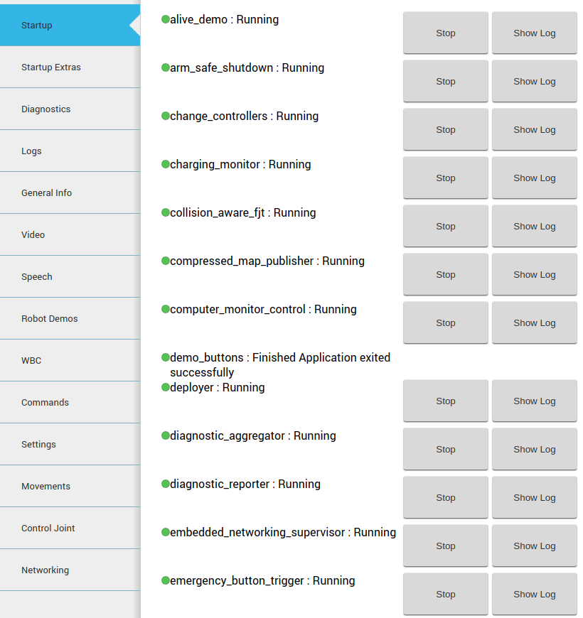
Figure: The startup tab displays the launched applications and their dependencies
13.3.2 The startup extras tab
Plugin: Startup
Description: This tab is optional, if present it will contain a list of PAL software which is not started by default during the boot up of the robot. These are optional features that need to be manually executed by the user.
13.3.3 Diagnostics tab
Plugin: Diagnostics
Description: Displays the current status of TIAGo++’s hardware and software.
The data is organized in an hierarchical tree. The first level contains the hardware and functionality categories.
The functionalities are the software elements that run in TIAGo++, such as vision or text to speech applications.
Hardware diagnostics contain the hardware’s status, readings and possible errors.
Inside the hardware and functionality categories, there’s an entry for each individual functionality or device. Some devices are grouped together (motors, sonars), but each device can still be seen in detail.
The color of the dots indicates the status of the application or component.
Green: No errors detected.
Yellow: One or more anomalies detected, but they are not critical.
Red: One or more errors were detected which can affect the behaviour of the robot
Black: Stale, no information about the status is being provided
An example of this display is shown in the figure below. The status of a particular category can be expanded by clicking on the “+” symbol to the left of the name of the category. This will provide information specific to the device or functionality. If there’s an error, an error code will be shown.
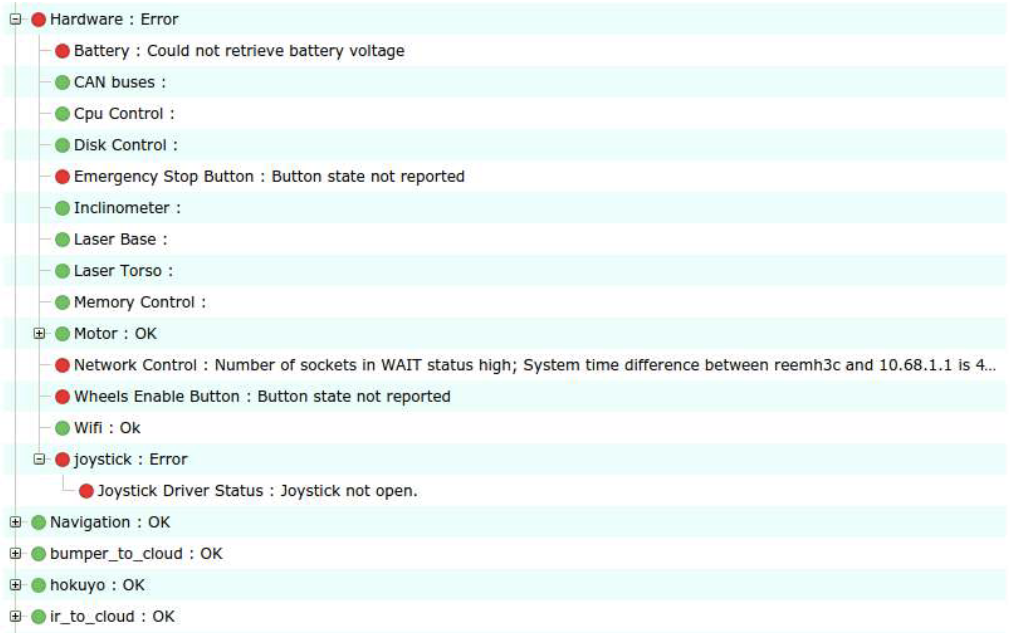
Figure: The Diagnostics tab displays the status of the hardware and software components of TIAGo++
13.3.4 Logs Tab
Plugin: Logs
Description: Displays the latest messages printed by the applications’ logging system.
The logs are grouped by severity levels, from high to low: Fatal, Error, Warn, Info and Debug.
The logs are updated in real time, but messages printed before opening the tab can’t be displayed.
The log tab has different check-boxes to filter the severity of the messages that are displayed. Disabling a priority level will also disable all the levels below it, but they can be manually enabled. For instance, unchecking Error will also uncheck Warn, Info and Debug levels, but the user can click on any of them to reenable them.
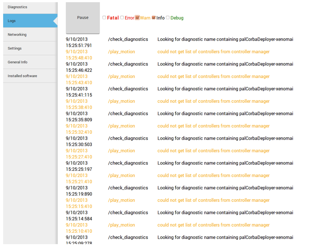
Figure: The Log Tab displays the log messages as they are being published in the robot
13.3.5 General Info Tab
Plugin: General Info
Description: Displays the robot model, part number and serial number.
13.3.6 Video Tab
Plugin: Video
Description: Displays the images from a ROS topic in the WebCommander.
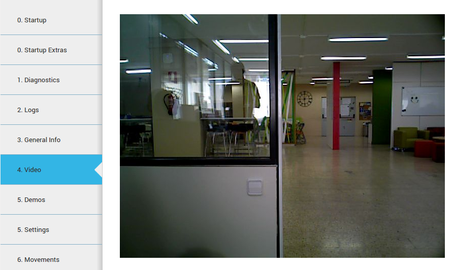
Figure: The Video Tab displays live video stream from the robot’s camera
13.3.7 Speech tab
Plugin: Commands
Description: Displays buttons to trigger voice synthesis with some predefined text. In addition to this, the tab features a top text box where the user can write any sentence and synthesize it with the robot’s voice by pressing the “Say” button in the choosen language.
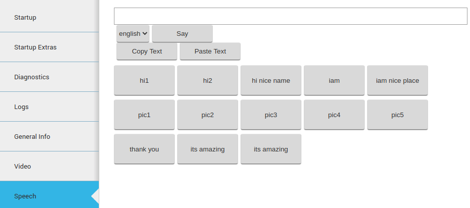
Figure: The Speech Tab displays predefined voice sentences
13.3.8 Robot Demos
Plugin: Commands
Description: This tab provides several out-of-the-box demos including:
Gravity compensation
Self presentation
Alive demo
Follow by Hand demo

Figure: The Robot Demos Tab allows execution of several demos
For details of each demo please refer to Section Demos accessible via WebCommander
13.3.9 WBC
Plugin: Commands
Description: Several demos based on Whole Body Control can be executed if the corresponding Premium Software Package is installed in the robot.
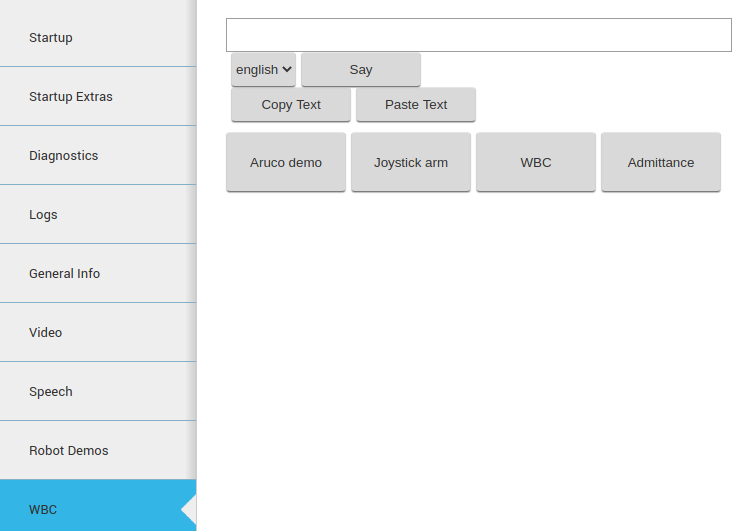
Figure: The WBC Tab displays several demos using Whole Body Control
For a comprehensive explanation on how the different demos work please refer to the 41 Change controllers chapter.
13.3.10 Commands
Plugin: Commands
Description: This tab provides several miscellaneous commands like:
Get out of collision: in case that the robot is in self-collision, or very close to this, this command will trigger a small movement so that the arm gets out of self-collision condition.
Default controllers: this button switches back to the default position controllers of the robot in case these have been changed.
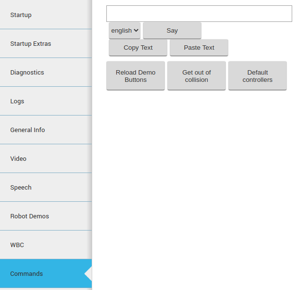
Figure: The WBC Tab displays several demos using Whole Body Control
13.3.11 Settings Tab
Plugin: Commands
Description: The settings tab allows to change the behaviour of TIAGo++.
Currently it allows to configure the language of TIAGo++ for speech synthesis. It is possible to select one from a drop down list. Changing the text-to-speech language will change the default language when sending sentences to be spoken by TIAGo++ (see section 23 Text-to-Speech synthesis for further details).
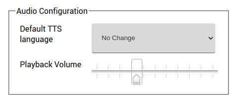
Figure: The Settings tab allows to modify the behaviour of TIAGo++
Software Configuration The Settings tab allows the user to configure some software of the robot. For example, the user can change the Diagnostic Severity reporting level so that, depending on this value, the robot will report certain errors by means of its LED stripes, voice, etc.
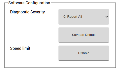
Figure: The Settings tab allows to modify the behaviour of TIAGo++
Hardware Configuration The Settings tab allows the user to configure the hardware of the robot. Hardware configuration will let the user to disable/enable the different motors, enable/disable the Arm module, choose different End Effector configuration, also also enable/disable the mounted F/T sensor.
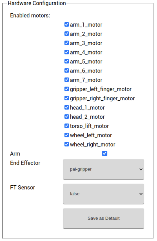
Figure: TIAGo++ Hardware Configuration
For instance, to disable the “head_1_motor”, untick the head_1_motor checkbox in the “Enabled motors” options. If you want to switch to a different end-effector, then in the “End Effector” drop down, select the end effector that you are going to install, and click the “Save as Default” button at the bottom of the section. Reboot the robot for the above selected configuration to be taken into effect.
Remote Support The Settings tab is equipped with the remote support connection widget. A technician from PAL Robotics can give remote assistance to the robot by connecting through this widget. Using an issue in the support portal, the PAL technician will provide the IP Address and the Port, this information need to be filled in the respective fields of the widget and then pressing the Connect button will allow for the remote assitance. If the robot needs to be rebooted, the customer has to activate the remote support after each reboot because it is not persistent.
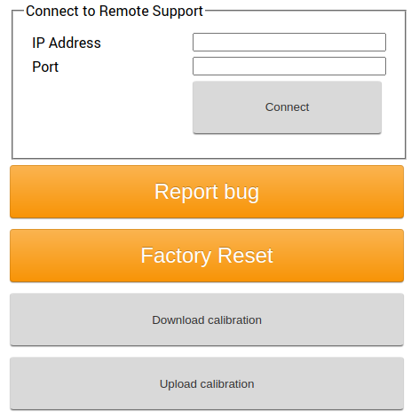
Figure: Remote support widget for TIAGo++
At any point of time after the connection had established, the remote connection can be terminated by clicking the Disconnect button.
Note
After clicking the Connect if the widget pops back to the normal, instead of showing the connection status, then it means that the robot is either not connected to internet (or) there should be some network issue.
13.3.12 Movements Tab
Plugin: Movements
Description: Enables playing pre-recorded motions on TIAGo++.
The movement tab that can be seen in the next figure allows a user to send upper body motion commands to the robot. Clicking on a motion will execute it immediately in the robot. Make sure the arms have enough room to move before sending a movement, to avoid possible collisions.
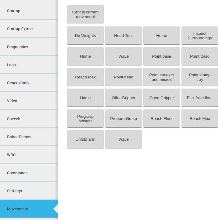
Figure: The Movement tab allows to send upper body motions to TIAGo++
13.3.13 Control Joint Tab
Plugin: JointCommander
Description: Enables moving individual joints of TIAGo++ with sliders.
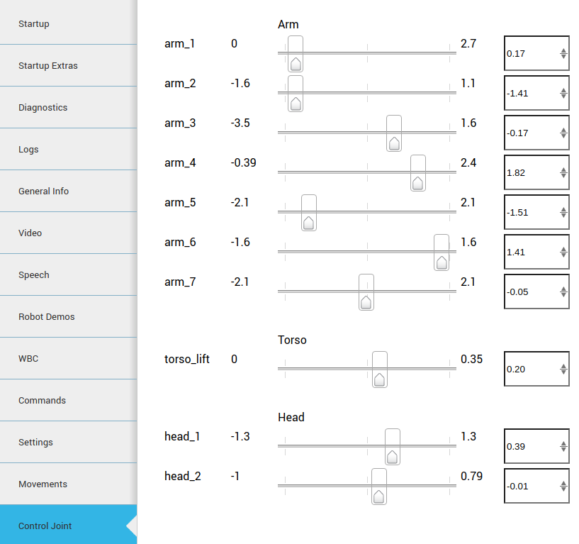
Figure: The Joint Control tab allows moving individual joint commands in position mode TIAGo++
13.3.14 Networking tab
Plugin NetworkingEmbedded
Description The figure below shows the networking tab. By default, the controls for changing the configuration are not visible in order to avoid access by multiple users.
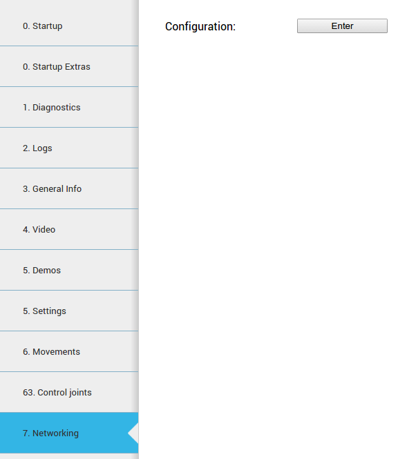
Figure: Networking configuration
If the Enter button is pressed, the tab connects to the network configuration system and the controls shown in the figure below will appear.
When a user connects to the configuration system, all the current clients are disconnected and a message is shown in the status line.
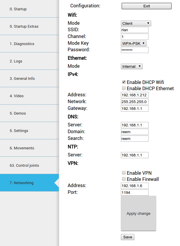
Figure: Networking configuration controls
Configurations are separated in different blocks:
Wifi:
Mode: Can be selected whether WiFi connection works as client or access point.
SSID: ID of the Wi-Fi to connect to client mode or to publish in access point mode.
Channel: When the robot is in access point mode, use this channel.
Mode Key: Encryption of the connection. For more specific configurations select manual. In this case it is used the file /etc/wpa_supplicant.conf.manual that can be manually created in the robot.
Password: Password for the WiFi connection
Ethernet:
Mode: Can be selected whether the ethernet connection works as an internal LAN or external connection(see Expansion Panel section).
IPv4
Enable DHCP Wifi: Enables DHCP client in WiFi interface.
Enable DHCP Ethernet: Enables DHCP client in the external ethernet port.
Address, Network, Gateway: In client mode, the manual values of the building’s network are used by the Wi-Fi interface. This is the same for the external ethernet port.
DNS
Server: DNS server.
Domain: Domain to use in the robot.
Search: Domain to use in the search.
VPN
Enable VPN: If the customer has a PAL basestation, the robot can be connected to the customer’s VPN.
Enable Firewall: When activating the VPN, a firewall can be connected to avoid an incoming connection from outside the VPN.
Address: Building network IP address of the basestation.
Port: Port of the basestation where the VPN server is listening.
No changes are set until the Apply change button is pressed.
When the Save button is pressed (and confirmed), the current configuration is stored in the hard disk. Be sure to have a correct networking configuration before saving it. A bad configuration can make it impossible to connect to the robot. If this happens, a general reinstallation is needed.
Changes to the WiFi between client and access point could require a reboot of the computer in order to be correctly applied.
Using the diagnostic tab, it is possible to see the current state of the WiFi connection.
Connecting to a LAN In order to connect to your own LAN follow the steps below.
First of all you need to access the WebCommander via the URL
http://tiago-0c:8080 and go to the
Networking tab. Press Enter button and then follow the
instructions shown in figure Figure: Networking configuration.
Once you have filled in the right configuration and pressed the Apply change button it is very important to wait until you are able to ping the new robot IP in your own LAN. If it does not happen you might have to reboot the robot as the configuration changes have not been saved yet. The robot will reboot with its previous networking configuration, allowing you to repeat the process properly.
When the new configuration allows you to detect the robot in your own
LAN then you may proceed to enter the WebCommander again and press
the Save button and then the Confirm button.
Setting as an Access Point In order to configure TIAGo++ as access point open the WebCommander via the URL
http://tiago-0c:8080 and go to the Networking tab. Press Enter button and then follow the instructions shown in the figure below.
Once you have filled in the right configuration and pressed the Apply change button it is very important to wait until the new Wi-Fi network is detected. A smartphone, a tablet or a computer provided with a WiFi card can be used for this purpose. If it does not happen you might have to reboot the robot as the configuration changes have not been saved yet. The robot will reboot with its previous networking configuration, allowing you to repeat the process properly.
When the new configuration allows you to detect the robot’s Wi-Fi then
you may proceed to enter the WebCommander after connecting to the
Wi-Fi of the robot and press the Save button and then the
Confirm button.
13.4 Tab configuration
The WebCommander is a configurable container for different types of content, and the configuration is done
through the /wt parameter in the ROS Parameter Server. On the robot’s startup, this parameter is loaded by
reading all the configuration files in /home/pal/.pal/wt/. For a file to be loaded, it needs to have a .yaml extension containing valid YAML syntax describing ROS Parameters: within the /wt namespace.
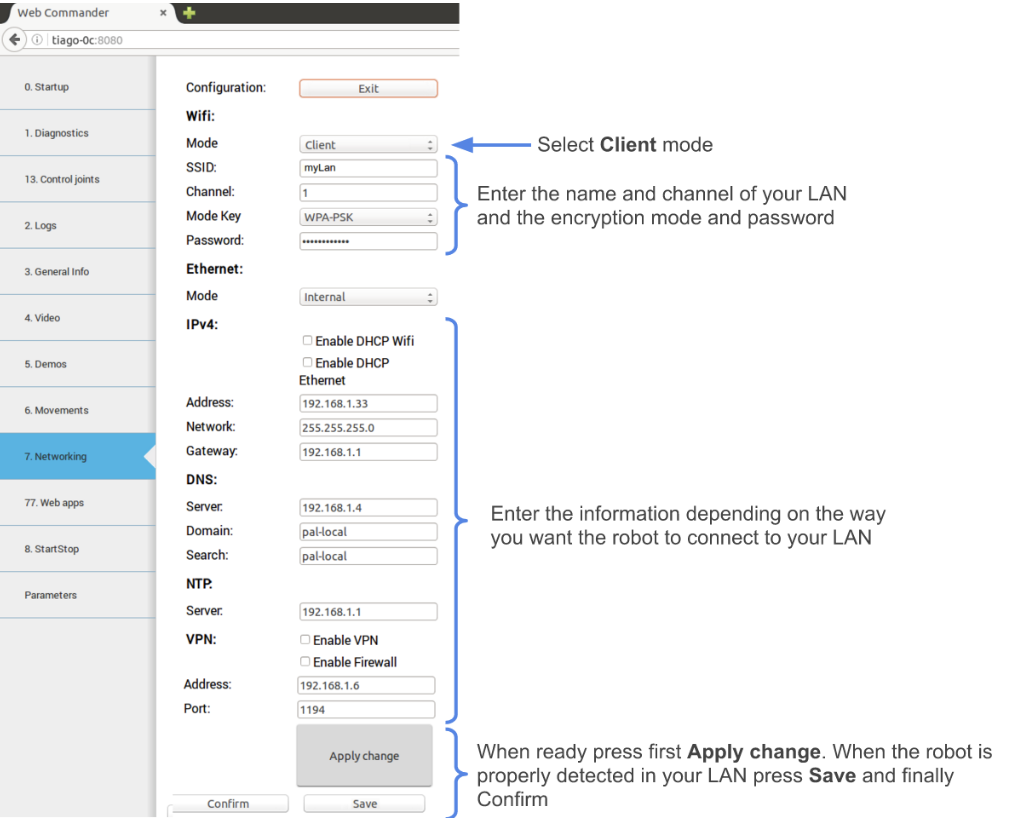
Figure: Configuring TIAGo++ to connect to a LAN
13.4.1 Parameter format
In the box below, an example of how a WebCommander configuration is displayed. It is a YAML file, where
/wt is a dictionary and each key in the dictionary creates a tab in the website with the key as the title of the tab.
Each element of the dictionary must contain a type key, whose value indicates the type of plugin to load. Additionally, it can have a parameters key with the parameters that the selected plugin requires.
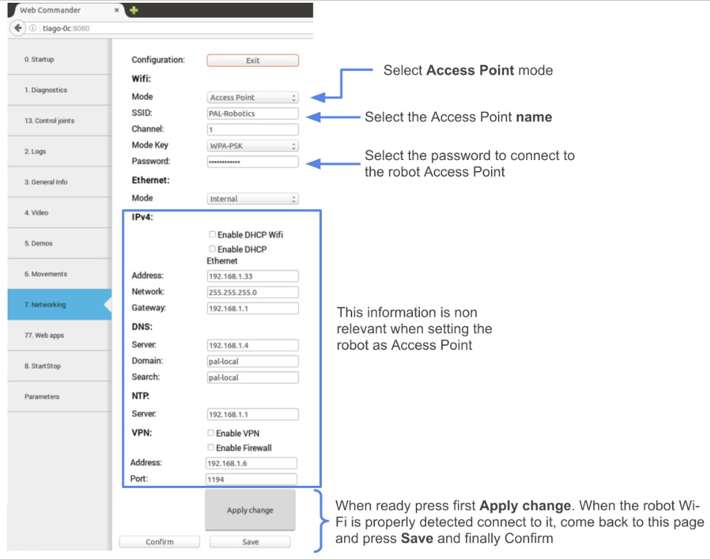
Figure: Configuring TIAGo++ to connect to a LAN
wt:
    "0. Startup":
        type: "Startup"
    "1. Diagnostics":
        type: "Diagnostics"
    "2. Logs":
        type: "Logs"
    "3. Behaviour":
        type: "Commands"
        Parameters::
            buttons:
              - name: "Say some text"
                say:
                      text: "This is the text that will be said"
                      lang: "en_GB"
              - name: "Unsafe Wave"
                motion:
                      name: "wave"
                      safe: False
                      plan: True
The Parameters: in the box of this section would create four tabs. Named “0. Startup”, “1. Diagnostics”, “2. Logs” and “3. Behaviour”, of the types Startup, Diagnostics, Logs and Commands respectively. The first three plugins do not require Parameters:, but the Command type does, as explained in the Command Plugin section.
13.4.2 Startup Plugin Configuration
Description: Displays the list of PAL software that is configured to be started in the robot, and whether it has been started or not.
Parameters:
startup_ids A list of strings that contains the startup groups handled the instance of the plugin. See section 17.1.3 Additional startup groups.
13.4.3 Diagnostics Plugin Configuration
Description: Displays the current status of TIAGo++’s hardware and software.
Parameters: None required
13.4.4 Logs Plugin Configuration
Description: Displays the latest messages printed by the applications’ logging system.
Parameters: None required
13.4.5 JointCommander Plugin Configuration
Description: This tab provides slides to move each joint of TIAGo++ ‘s upper body.
Parameters: A list of the joints groups to be controlled. Each element of the list must be a dictionary containing “name”, “command_topic” and “joints”. Where “name“ is the name that will be displayed for this group, “command_topic” is the topic where the joint commands will be published and “joints” is a list containing the joint names to be commanded.
Example:
"8. Control Joint":
    type: "JointCommander"
    Parameters::
    - name: Arm
      command_topic: /arm_controller/safe_command
      joints: [arm_1_joint, arm_2_joint, arm_3_joint, arm_4_joint, arm_5
    - name: Torso
      command_topic: /torso_controller/safe_command
      joints: [torso_lift_joint]
    - name: Head
      command_topic: /head_controller/command
      joints: [head_1_joint, head_2_joint]
13.4.6 General Info Plugin Configuration
Description: Displays the robot model, part number and serial number.
Parameters: None required
13.4.7 Installed Software Plugin Configuration
Description: Displays the list of all the software packages installed in both the robot’s computers.
Parameters: None required
13.4.8 Settings Plugin Configuration
Description: The settings tab allows to change the behaviour of TIAGo++.
Parameters: None required
13.4.9 NetworkingEmbedded Plugin Configuration
Description: This tab allows to change the network configuration.
Parameters: None required
13.4.10 Video Plugin Configuration
Description: Displays the images from a ROS topic in the WebCommander
Parameters:
topic Name of the topic to read images from, for instance: /xtion/rgb/image_raw/compressed
Figure: The Video Tab displays live video stream from the robot’s camera
13.4.11 Movements Plugin Configuration
Description: Enables playing pre-recorded motions on TIAGo++.
Parameters:
goal_type Either “play_motion” or “motion_manager”. Determines which action server will be used for sending the motions.
13.4.12 Commands Plugin Configuration
Description: Contains buttons that can be programmed through parameters to perform actions in the robot.
Parameters:
buttons A list of buttons, where each button is a dictionary with 2 fields. The name field is the text displayed on the button, and the second field name determines the type of button and is a dictionary with the configuration of the button.
wt:
    "Example Buttons":
        type: "Commands"
        Parameters::
            buttons:
                - name: "Say some text"
                  say:
                        text: "This is the text that will be said"
                        lang: "en_GB"
                - name: "Greetings"
                  say_tts:
                        section: "macro"
                        key: "greetings"
                        lang: ""
                - name: "Wave"
                  motion:
                        name: "wave"
                        safe: True
                        plan: True
                - name: "Change to Localization"
                  remote_shell:
                    cmd: "rosservice call  /pal_navigation_sm  \"input: 'LOC'\""
                    target: "control"
There are 4 types of buttons: say, say_tts, motion and remote_shell
say Sends a text to the Text-To-Speech engine. It requires a text field containing the text to be said, and lang containing the language in the format language_country specified in the RFC 3066.
say_tts Sends text as a section/key pair to the Text-To-Speech engine. It requires a section and key field
as specified in section 23.2.2 Action interface. The lang field can be left empty, but if it is specified it must be in the RFC336 format.
motion Sends a motion to the motion manager engine. Requires a name field specifying the name of the
motion, and two boolean fields plan and safe that determine to check for self-collisions and collisions
with the environment respectively. For safety reasons they should always be set to True.
remote_shell Enables the execution of a bash command in one of the robot’s computers. Requires a cmd
field containing a properly escaped, single line bash command, and a target field that can either be
control or multimedia, indicating to execute the command in the control computer or in the multimedia
computer of the robot.
Both say and say_tts require that the robot is running PAL Robotics’ TTS software.
14 Web User Interface
14.1 Overview
This section explains the use TIAGo++’s Web User Interface and its different plugins. The Web User Interface is a tool designed to simplify the configuration of the robot as well as the user experience. The Web User Interface can be accessed via browser, at the address http://tiago_dual-Xc, where X is the serial number of the robot.
14.2 Technical considerations
At the moment the Web User Interface supports only the Chrome browser on a laptop or computer. Accessing the Web User Interface from a mobile phone or tablet, or from a different browser, will result in some of the functions not working properly or at all.
14.3 Login screen
When accessing the Web User Interface a user and password will be requested. The default user and password is pal / pal . Once the correct user and password are introduced the user will automatically be redirected to the page he was accessing.
Sessions are not time-constrained, which means that once a user has logged in he won’t be logged out until either he closes the browser or the robot is rebooted.
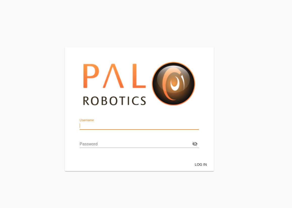
Figure: Login screen of the WebGUI.
14.4 Navigation between plugins
The menu on the left side contains the different plugins that are accessible for the user, depending on the configuration selected. Moving the mouse over the icons will show a tooltip to indicate the plugin name. Clicking on the menu icon on the top-left corner will open the menu, revealing both name and icon of the plugin. Clicking on an icon will redirect the user to the plugin.
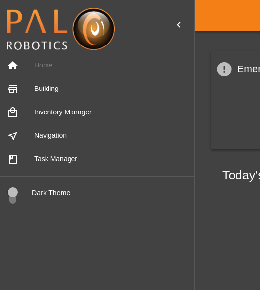
Open navigation menu, with dark theme enabled.
The switch that can be found under the icons allows the user to change between light and dark themes for the WebGUI.
14.5 Information Panel
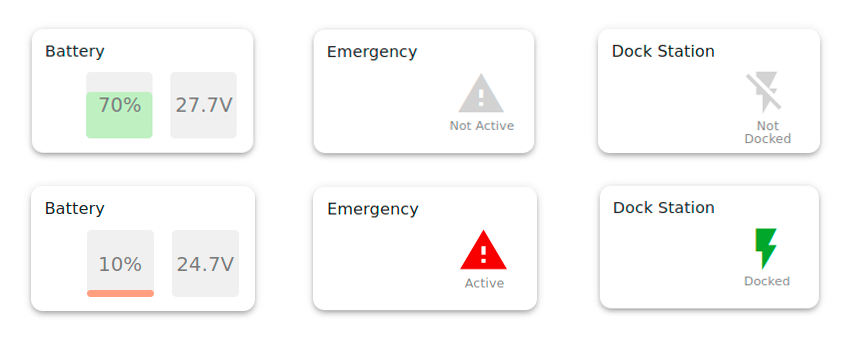
The Information Panel serves to provide visual information on the robot’s current state.
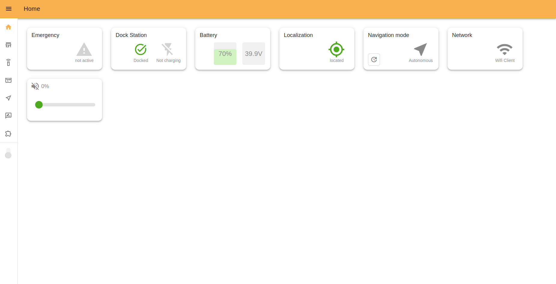
Emergency indicates the emergency button status (pressed or not). In the case of it being pressed, the icon will be red.
Dock Station indicates if the robot is connected to the dock or either with the charging connector.
Battery shows the current battery percentage and voltage. Yellow and red colors indicate middle and low battery levels.
Localization shows if the robot is located correctly in the navigation map.
Navigation Mode shows how the robot is moving: autonomously, by joystick input or if navigation is paused.
Network indicates the currently active connection mode of the robot. Can be: Wi-fi Client or Access point.
Volume allows management of the robot’s volume and shows the current volume percentage.
Some examples that may be displayed:
14.6 Command desks
With this app, you can teleoperate the robot, and prepare it for events or other needs, by creating Command desks with groups of buttons inside them. Then you assign actions that the robot will perform when you click any button.
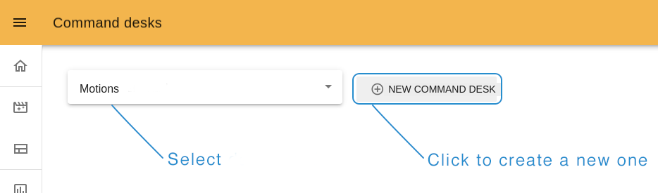
To create a new command desk click on the “NEW COMMAND DESK” button at the top of the page. Near it, at the left top corner menu, you can choose a Command desk created earlier.
14.6.1 Create a new desk
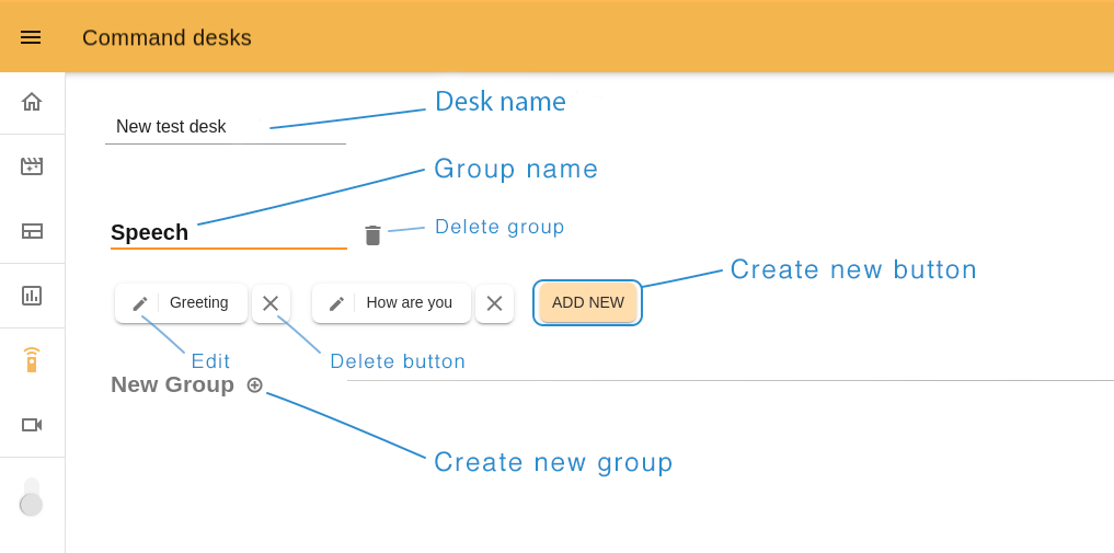
Type the name of your desk and create a first group (you must have at least one) by clicking on the “plus” icon near the “New group” title. To create a new button, click “ADD NEW”.
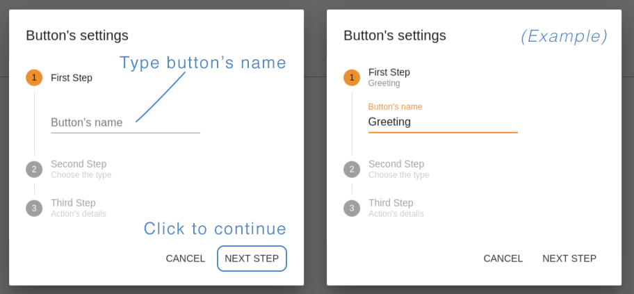
Step 1. Button’s name. Choose a name related to the action this button will perform.
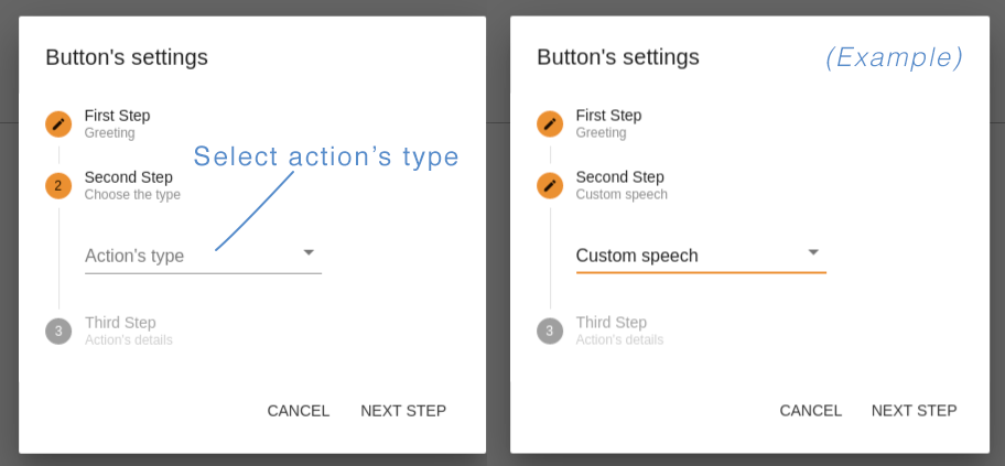
Step 2. Action’s type. You can create buttons with “Motion” type (14.8 Motion Builder), corresponding to the blue circles, so that the robot makes a movement, “Presentation” with a dark brown circle to execute your prerecorded (14.7 Presentations) or “Custom Speech type”, which is represented by an orange circle, so that the robot says the written text. In this example we chose “Custom speech”.
The available list of action types depends on the the installed web apps and the robot.
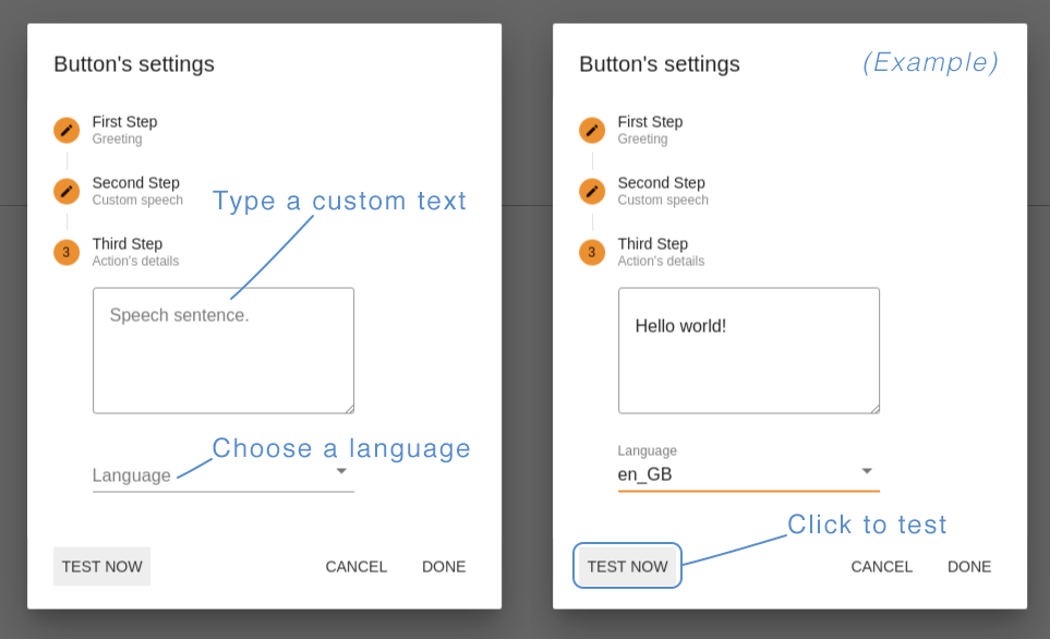
Step 3. Action’s details. Here you should define what TIAGo++ will do after clicking on this button. For “Motion” or “Presentation”, choose an option from the list, for “Custom speech” type a custom text for TIAGo++ to say, and choose the corresponding language.
The button “TEST NOW” allows you to try your button in action before saving it. If all is ok, click “DONE” to save and close the button editor.
After creating all the buttons you need, click “SAVE” at the right top of the page to exit the Edit mode and return to the Command desk page.
To play the Command press on the the button of the command you would like to execute.
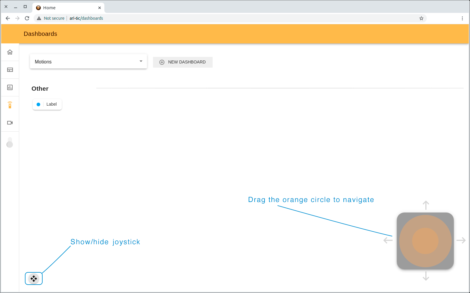
14.6.2 Joystick
With this webapp you can also navigate the robot. The small joystick button at the bottom of the page opens a virtual joystick. Drag the orange circle towards the direction you wish to move the robot.
14.7 Presentations
Presentations is a webapp that allows you to create prerecorded presentations (a combination of Speech, Motions, Touchscreen content and LEDs effects) and execute them.
The features of the Presentations tool include:
Creating, Editing, Deleting presentations and presentation slides
Adding the custom text to speech in a chosen language
Adding motions (previously created in MotionBuilder)
Managing the content on the touchscreen and it’s duration
Choosing and tuning the LED effects
Managing all possible combinations of presentation elements on a graphical timeline
Storing and executing the presentation
The interface of Presentations consists of a list of the presentations and a user-friendly editor, where you can create, edit and test presentations from your PC or mobile devices.
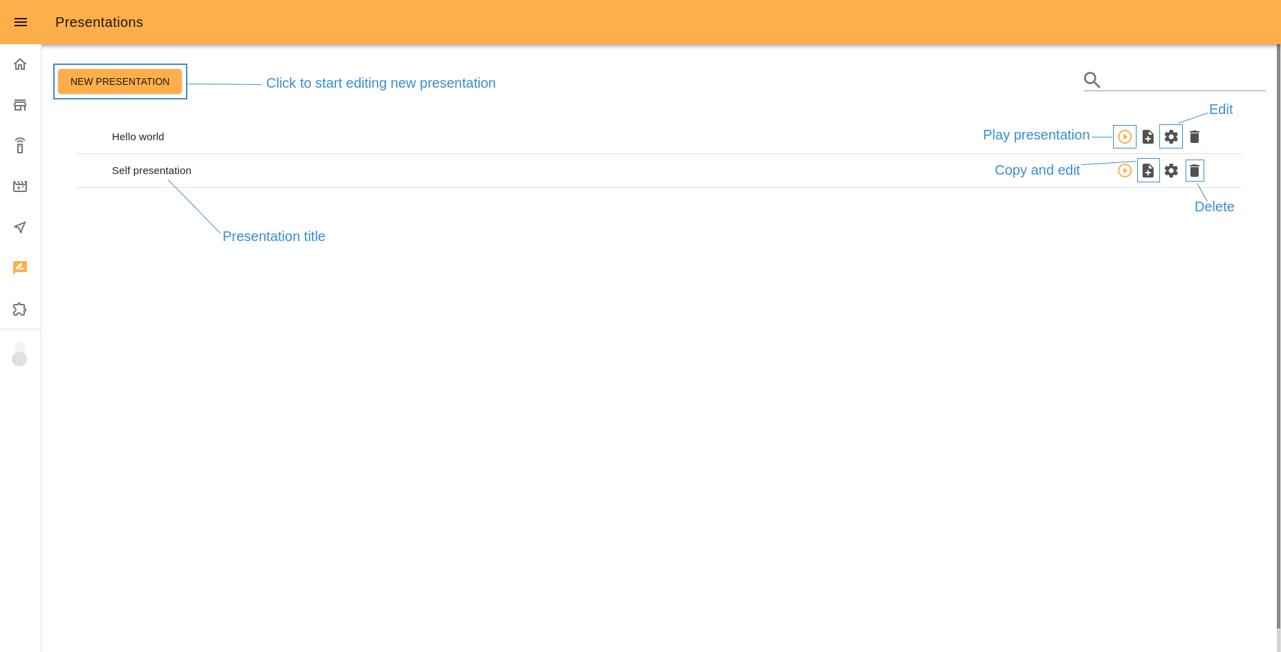
14.7.1 Homepage interface
The start page of Presentations serves not only to display the list of stored presentations but also to manage them. From here you can execute any presentation, edit or delete it. To quickly search it is useful to use the search by title bar.
To open the Presentations editor click the “Create new presentation” button or “Edit” icon of an existing presentation.
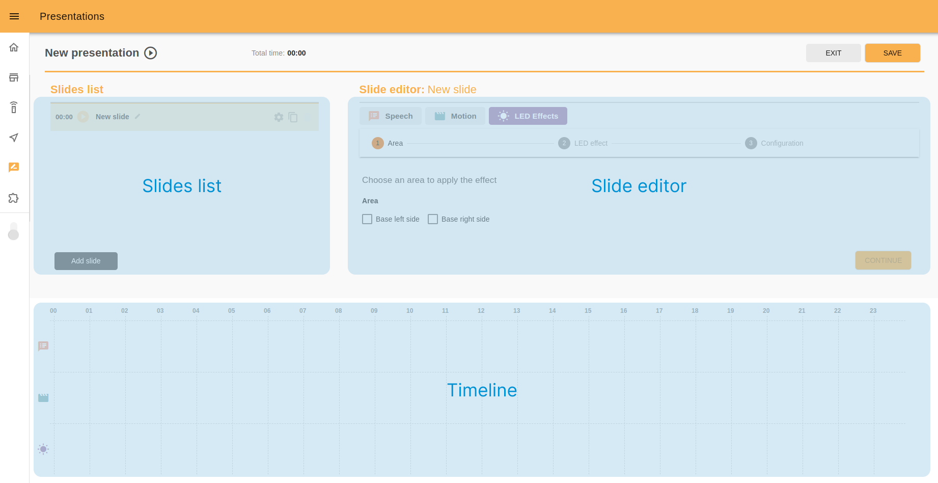
14.7.2 Editor interface
Let’s see what the interface Presentations has and how to interact with it. In the picture below you can see the principal parts of the editor: slides list, slide editor, timeline.
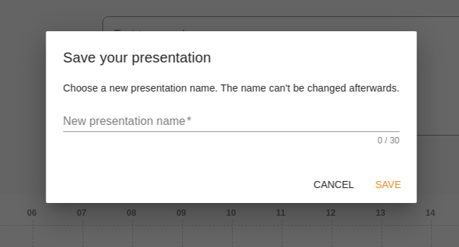
14.7.3 Presentation name
On the left top of the page there is a current presentation name with the Play presentation icon.
In case you are editing the new presentation after clicking the “Save” button you will see the popup with text input to set the presentation title. This step must be performed only once and the existing presentation cannot be renamed afterwards.
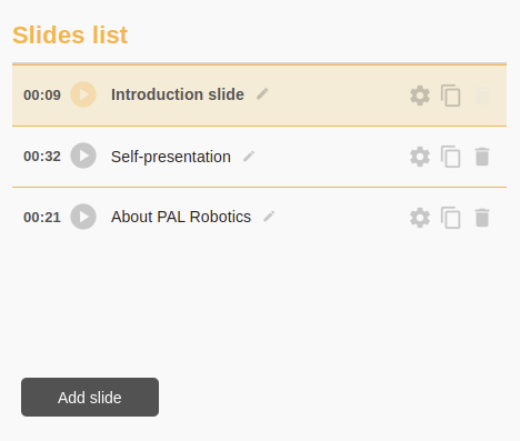
14.7.4 Slides list
It is good practice to divide your presentation to slides by the use case logic. In the slide list you can manage slides, add new ones, rename slides, delete, edit or play slides separately.
The slide you are editing right now will have a different color style.
14.7.5 Slide editor
In this panel you can edit the elements you want to include in your presentation. For now there are four tabs: speech, motion, touchscreen and LED’s effects.
To add text to speech, choose the “Speech” tab, input the desired phrase on the text input, choose the corresponding language and click the “ADD” button.
A new block with the same color as the “Speech” tab will appear below on the timeline. The duration of each text block is computed by the robot so you cannot make ARI speech quicker or slower. However you can divide your text into small phrases or separated words, if you need, and add them to the presentation one by one.
To add a motion to your presentation go to the “Motion” tab, choose the needed motion from the list and click the “ADD” button.
A new block with the “Motion” tab color will appear on the second row of the timeline below. The duration of motions and other settings should be edited in the 14.8 Motion Builder app.
To manage the LED’s effects use the last tab. As a first step, choose the robot devices that you want to play the effect.
In the second step choose the effect you want and depending on this the third step may be slightly different.
Tune the timing for the effect, set the duration in seconds (you can use the quick-options buttons to set 3, 5 seconds duration in one click) and save changes.
Again you will see the new block on the timeline (this time on the last timeline row).

14.7.6 Timeline
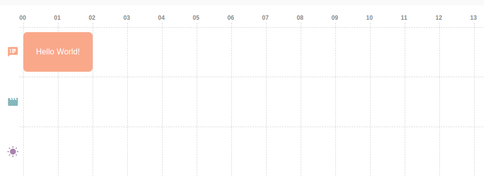
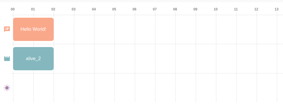
After adding a new element to the presentation it will appear graphically on the timeline as a colored block. The colors match with the color of the slide editor tabs. For example, pink for the speech blocks, blue for the motions, etc.
Each presentation element has its own row on the timeline. So, on the first row at all times only pink speech blocks will appear, on the second - motions and on the third row - LED’s effects.
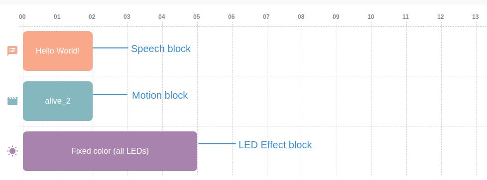
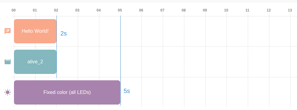
The width of each block corresponds to its duration in seconds that are shown on the timeline as vertical lines.
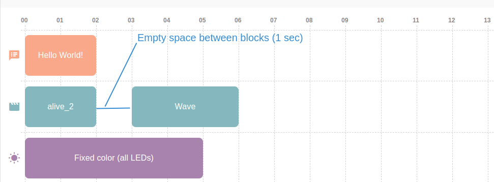
You can also leave space between blocks to separate the execution or delay the play of a block.
You can drag the blocks using the cursor or touching it (for the tablets) and decide the position of each one on the timeline. This way you can make some actions start at the same time (for example, say the “Hello” word and make a “Waving” movement) and create a time pause between blocks.
You can select one block by clicking it. Graphically it will change color. You will see the settings of the selected block on the slide editor tab, which will open automatically. There you can edit it and save the changes.
Also you can copy the selected block as the next or as the last one or delete it. For this use the small icons that appear on the top of the block when you select them.
14.7.7 Play presentation
As the presentation consists of the slides, firstly you have an option to play each slide individually while you edit the presentation. To do it click the “Play” icon close to the chosen slide title.
Of course, you can play the whole presentation. To play it from the Editor click the “Play” button on the left top of the page close to the presentation name.
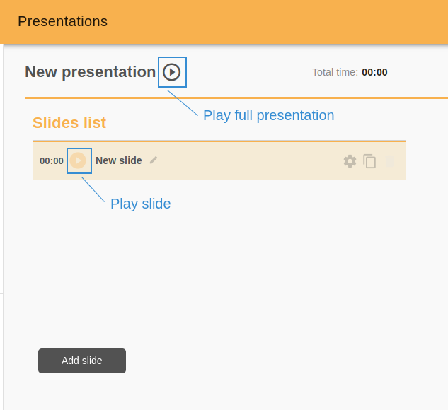
To do it from the start page, click the “Play” icon of the presentation from the list.
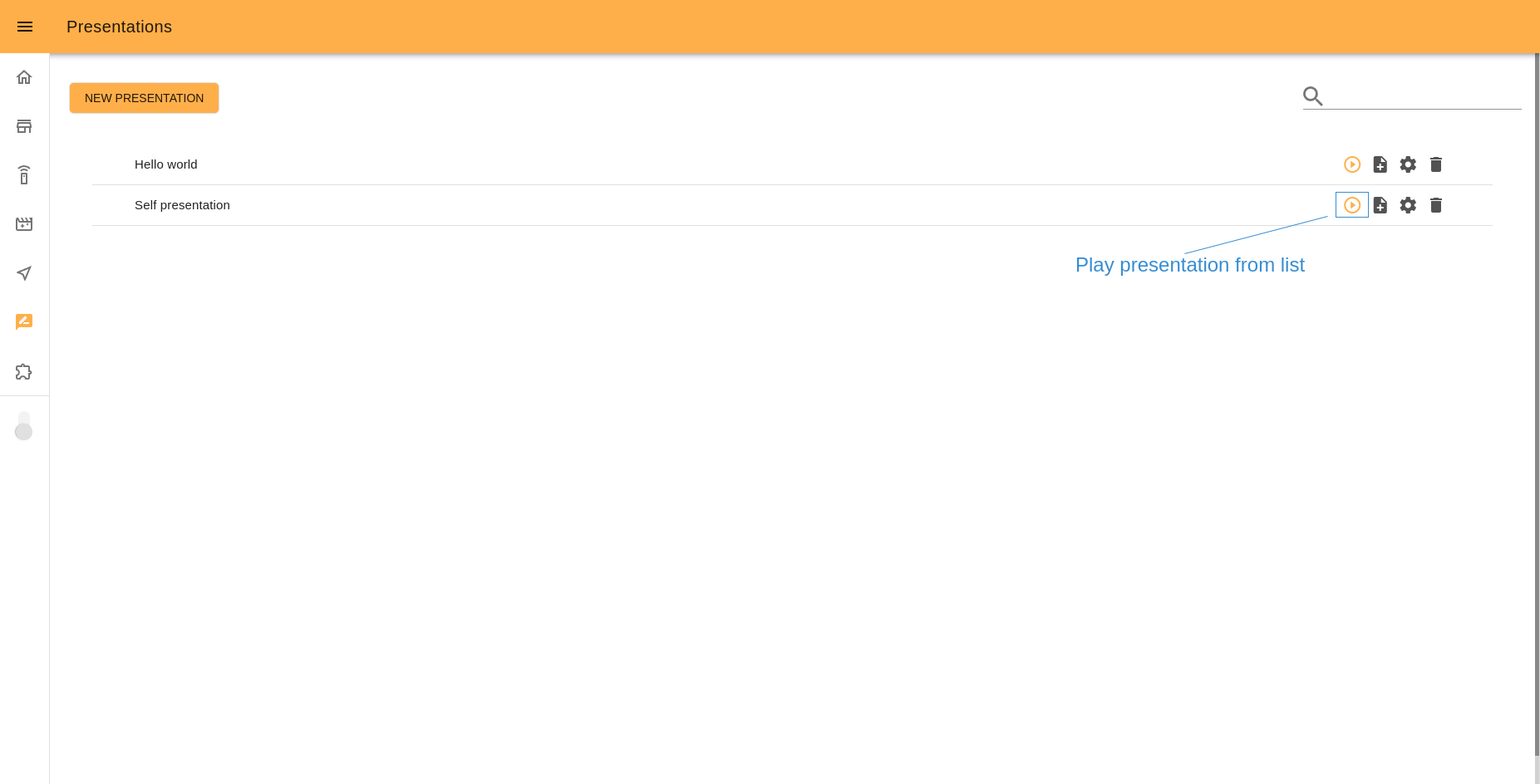
Just like Motions (created in 14.8 Motion Builder) you can play Presentations from the 14.6 Command desks.
Also in Touchscreen Manager you can create a “Page with buttons” or “Slideshow” template and assign any presentation to a button on the screen. When a user touches this button, ARI will execute the presentation.
14.7.8 Save presentation
On the top right of the editor there are two buttons: “Exit” and “Save”.
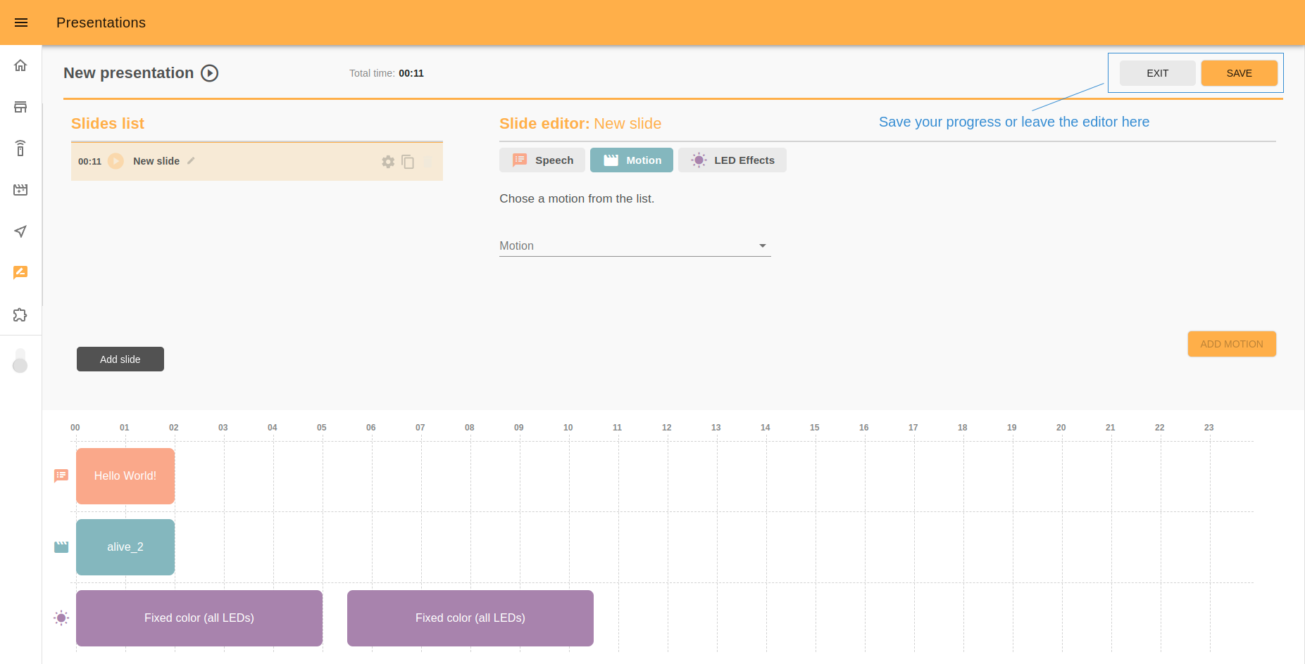
If you click the first button you will see the popup with two options: “Exit” (without saving changes) and “Exit and Save” to do both things.
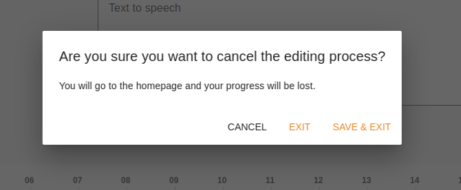
If you click “Save” you can save the current progress without leaving the editor.
In the case of saving a new presentation for the first time, the editor will ask you to create a name for your presentation, as the app cannot save presentations that don’t have a name.
14.7.9 Mobile version
You can create/edit presentations from your mobile or tablet device. For different screens the interface will be slightly different.
On tablets: when you open the Presentations Editor, firstly you will see the list of slides. Play, edit slide name, copy or delete slides from there. To edit the slide content click to the Settings icon and you will see the slide editor and timeline. To go back to the slides list click the “Back” button on the right top.
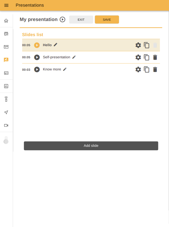
|
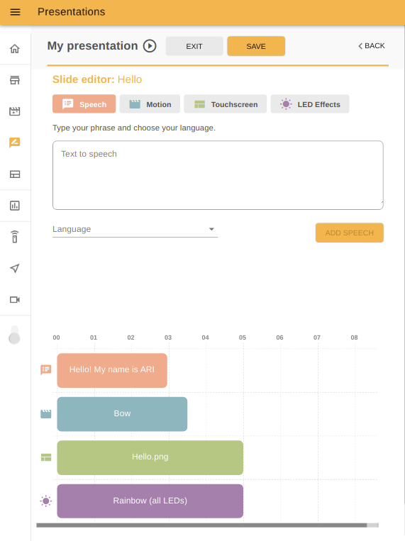
|
On mobiles: the slides list has the same interface as for tablets, to access the slide editor click to the icon of the element you want to edit on the bottom of the screen. In case you want to edit some block on the timeline, select it first and click to the corresponding slide editor icon.
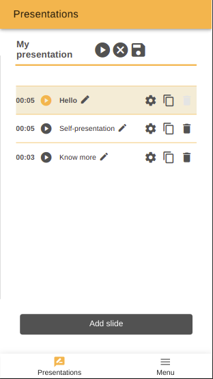
|
|
14.8 Motion Builder
The Motion Builder is a webapp that allows you to create prerecorded motions and execute them.
The features of Motion Builder tool include:
Creating, Editing, Deleting Motions
Adding, Editing and Deleting keyframes
Positioning the robot in any keyframe
Managing joints and groups used for the motion
Executing the motion at different speeds for testing purposes
Store the motion
The interface of Motion Builder consists of a list of the motions and a user-friendly editor, where you can create, edit and test motions without special technical skills.
14.8.1 Homepage interface
The start page of Motion Builder serves not only to display stored motions but also to manage them. From here you can execute any motion, create a copy and edit it, edit motion, delete it. Functions “Edit” and “Delete” are active only for motions created by the user.
Motions that have a star icon are default motions and can’t be edited or deleted. Click “Copy and edit icon” to use them as an example or a part of a new motion.
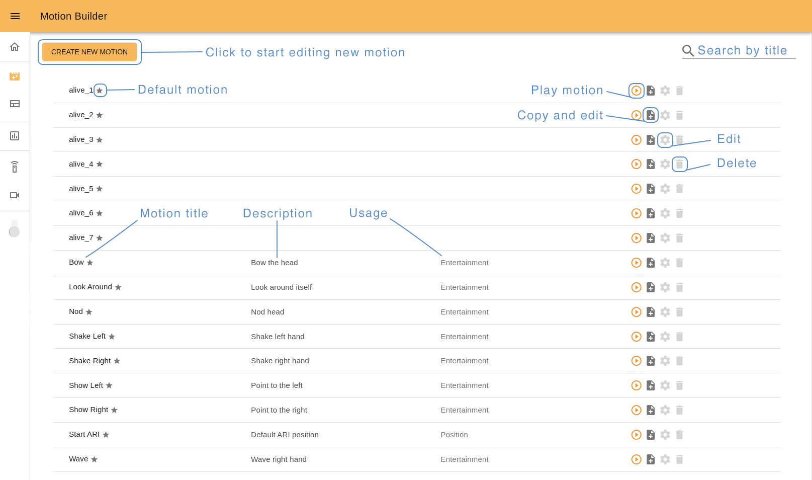
Use Search input (loupe icon) to browse the list easier. Start by typing the name of the motion you are looking for and you will see the corresponding results.
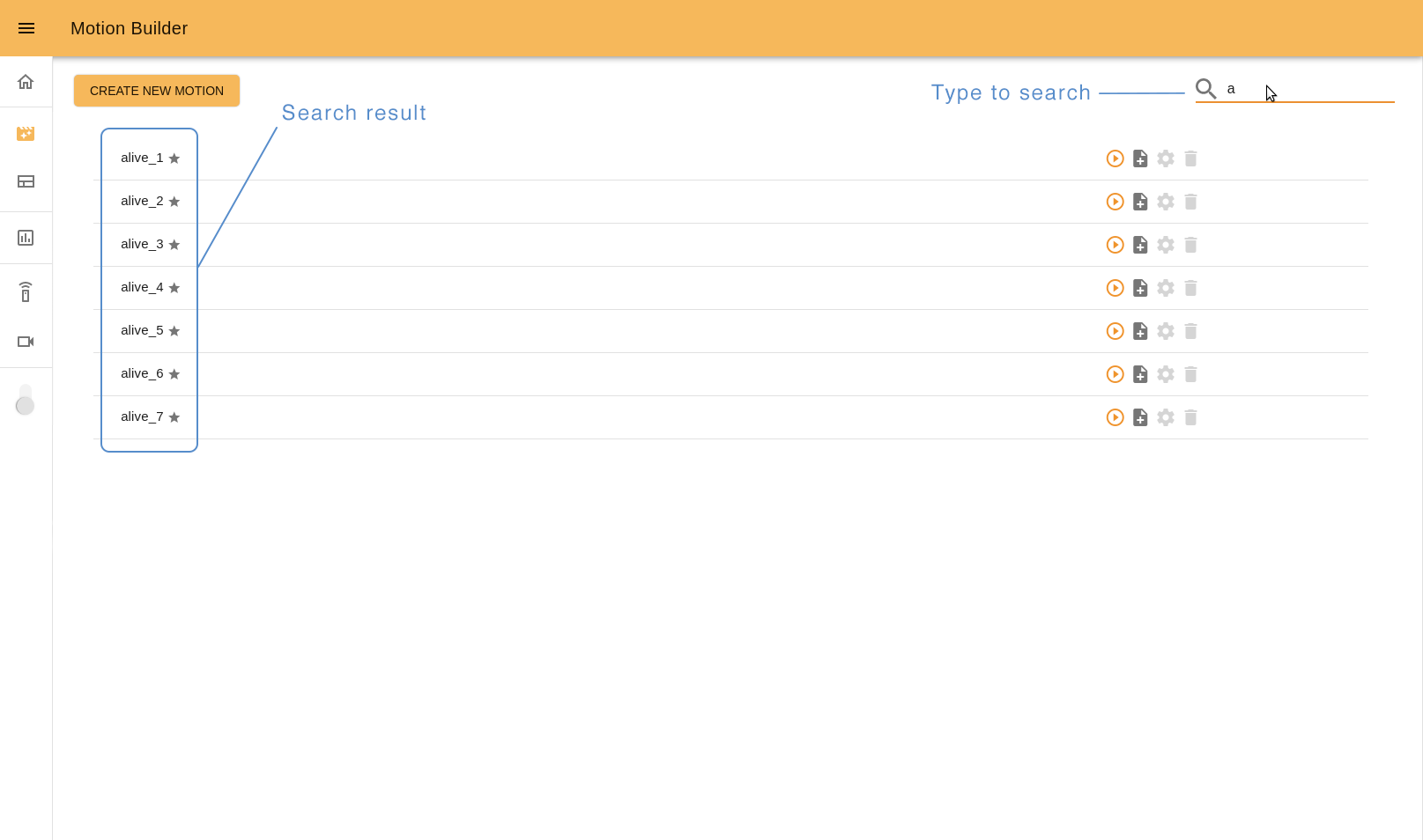
To open the Motion Builder editor click “Create new motion” button, “Copy and edit” or “Edit” icons.
14.8.2 It’s important to know before starting
Each movement consists of a group of robot motors poses (keyframes) that the user has to define and capture.
The first you need to do is to position the robot in the desired keyframe. There are two ways to do it: by positioning the robot manually (Gravity compensation mode - optional package) or by using online Editor tools (Position mode).
In Gravity compensation mode the robot doesn’t have a motor control. You can freely fix the position of the robot’s arm joints moving them manually. In Position mode you can control the robot position by using the online tools: sliders and joystick.
You can switch between different control modes instantly.
So to create a whole movement, capture the robot’s keyframes in the desired order.
14.8.3 Editor interface
Let’s see what the interface Motion Builder has and how to interact with it.
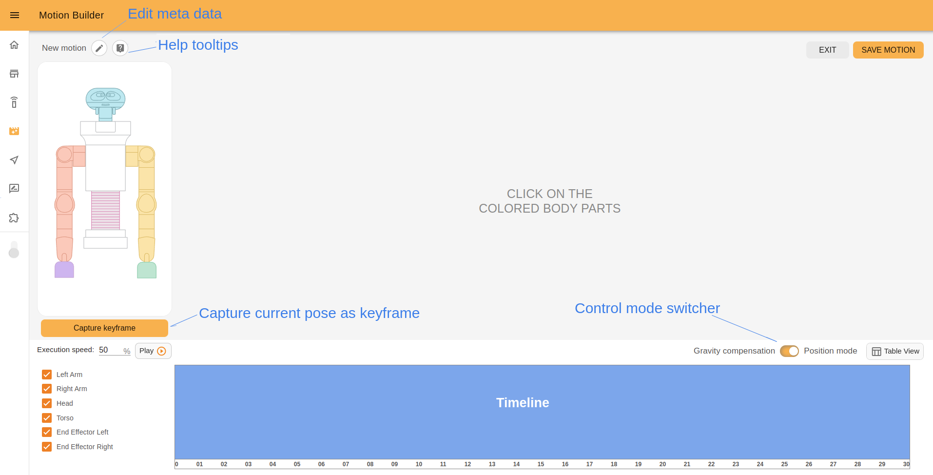
On the left top of the page there is a current motion name, “Edit meta” button and “Help mode” button.
14.8.4 Edit meta popup
Click the “Edit meta” button to set meta data of your motion: required ROS name, title, short description, and usage. This info is displayed on the Motion Builder start page (normally the ROS name is not shown but if a motion title wasn’t set previously, ROS name is used instead of it).
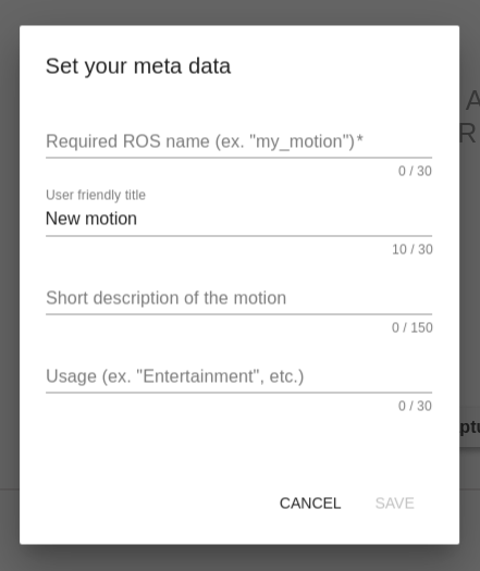
ROS name is a required field. It should be a unique word that describes the motions, starts with a letter and consists of the letters, numbers and _. It’s not allowed to change it after saving a new motion. Examples, “nod”, “shake_1”, “shake_2”, etc.
User friendly title should be a word or short phrase that helps you quickly understand what the motion does. It’s not a required field but it’s a good practise to fill it as well. Examples, “Nod”, “Shake Left”, “Shake Right”, etc.
In a short description field, you can describe some important details of the motion to distinguish it easily from the others. Examples, “Nod head”, “Shake right hand”, “Shake left hand”, etc.
In a usage field define the main usage of the motion. It is also a good practise to fill it because in the 14.6 Command desks webapp (“Motions” desk), you will see all your motions divided precisely by Usage names. Examples, “Entertainment”, “Greeting”, “Dance”, etc.
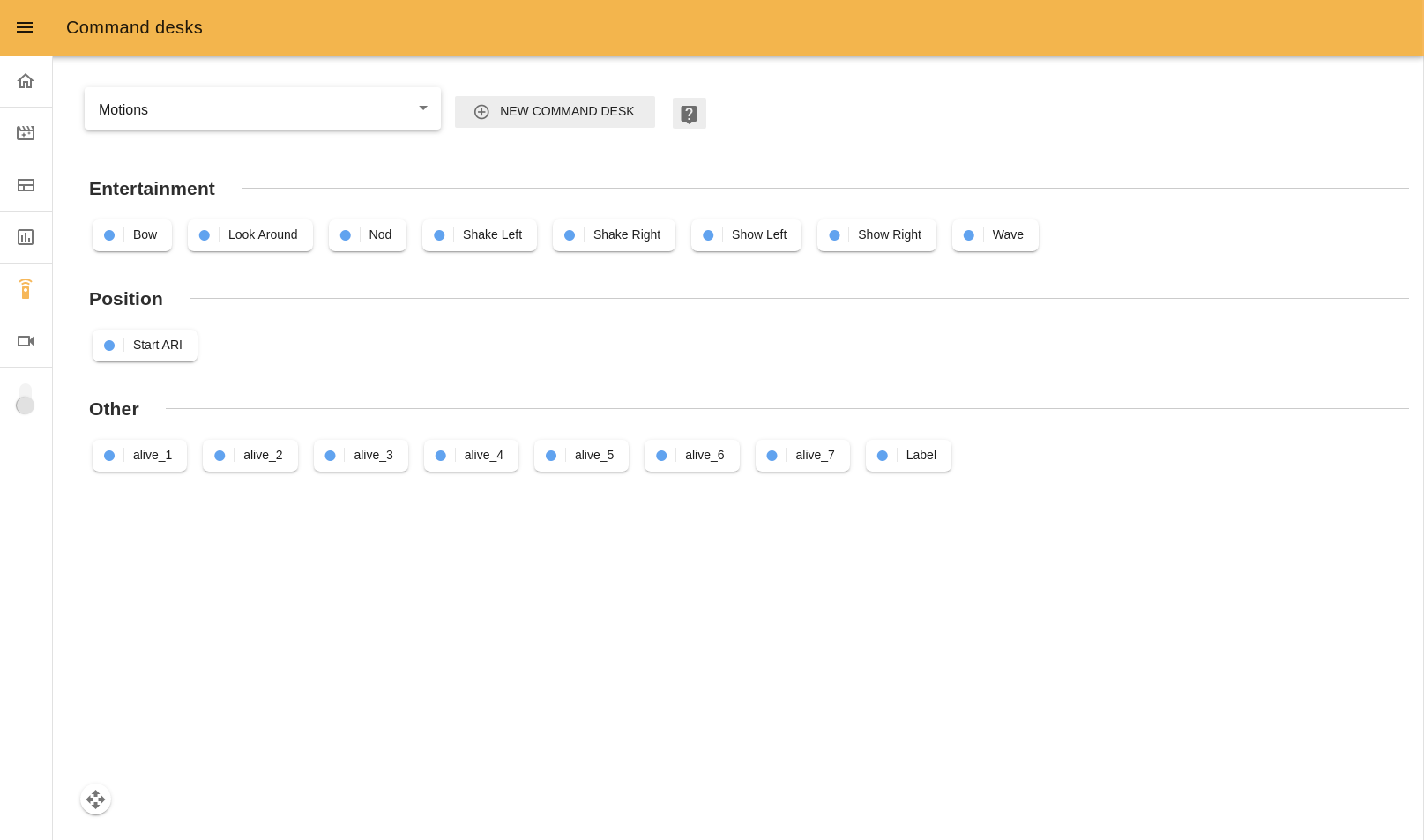
14.8.5 Help tooltips
“Help mode” button shows/hides help tooltips on the screen. If you click this button you will see blue icons with question signs. Hover the cursor over any icon to read a tip about Motion Builder usage.
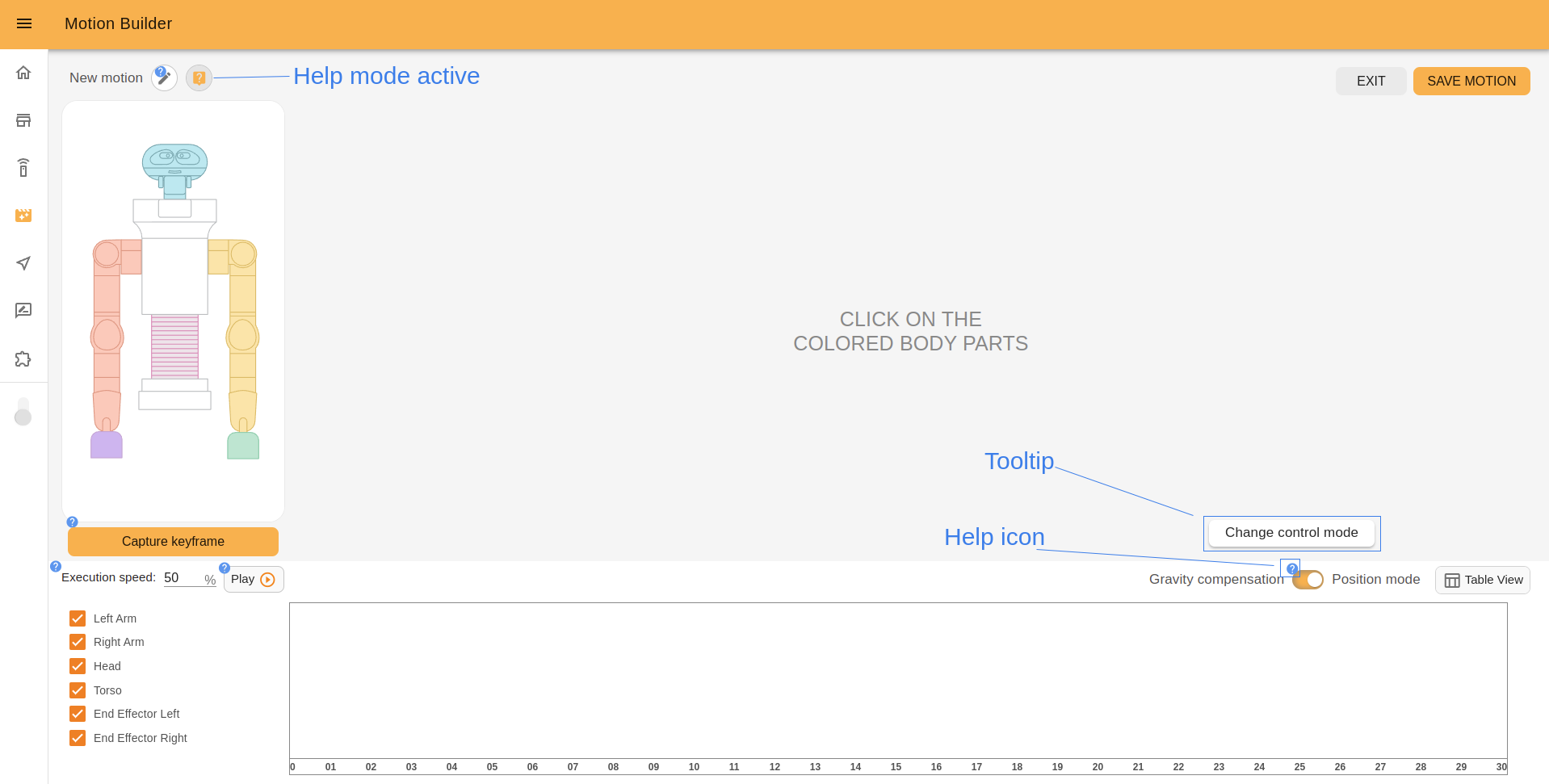
14.8.6 Position mode
In the timeline zone there is a switcher between the different control modes. You can use it any moment during the moment during the editing process.
When the Position mode is active, you can interact with the TIAGo++ image.
The painted parts are available to choose. For example, click TIAGo++’s head to control it.
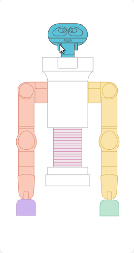
You also can manage joints and groups used for motion. Check the box with joints names on the bottom left of the page to add or remove it. In the example below we removed TIAGo++’s head from the motion and now it’s not painted on the interactive image.
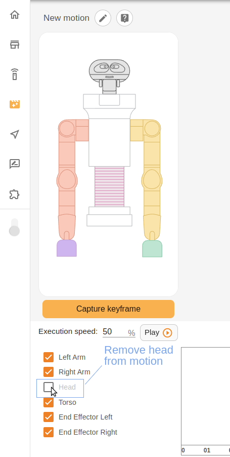
14.8.7 Joystick
To control TIAGo++’s head use a joystick. Just drag the orange circle (green when the cursor is over it) and watch how the pose of the robot’s head changes.
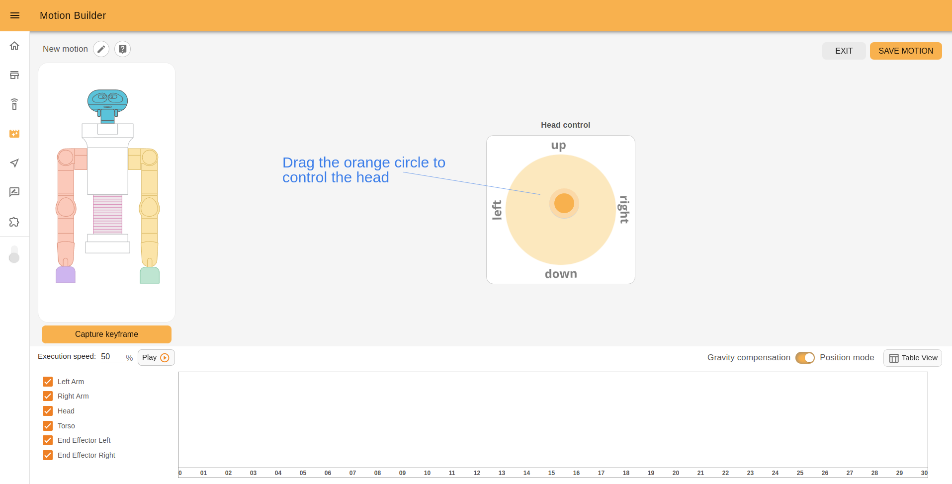
When you move a joystick quickly, for a short time it’s possible that the robot didn’t change its pose yet. In this case you will see a grey circle that shows the current pose of the head. When the robot has the same pose as the joystick, the grey circle will disappear.
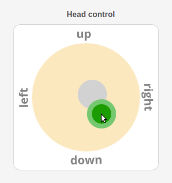
Click the “Capture it” button to store the keyframe.

14.8.8 Sliders
Sliders are used to control other groups of robots joints. Let’s click TIAGo++’s arm.
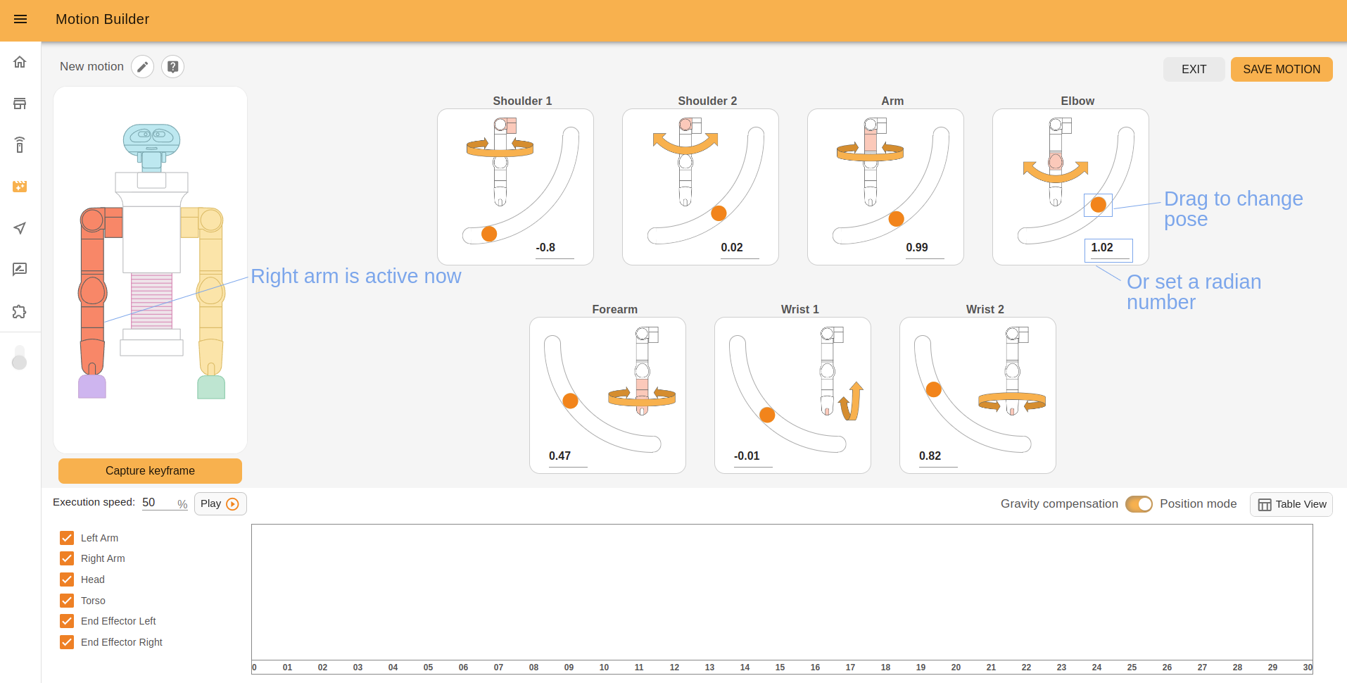
TIAGo++’s arm consists of a group of joints. You can create complex motion by changing the joints pose by separate.
Each joint has a title and a description image. To control the joint, drag a slider circle or change the position number in the input field (type a desired number or use arrows).
Click the “Capture it” button to store the keyframe.
14.8.9 Gravity compensation mode
When the Gravity compensation mode is chosen, TIAGo++’s image will not be interactive. You can change the robot arm poses manually and click the “Capture it” button to store the keyframe.
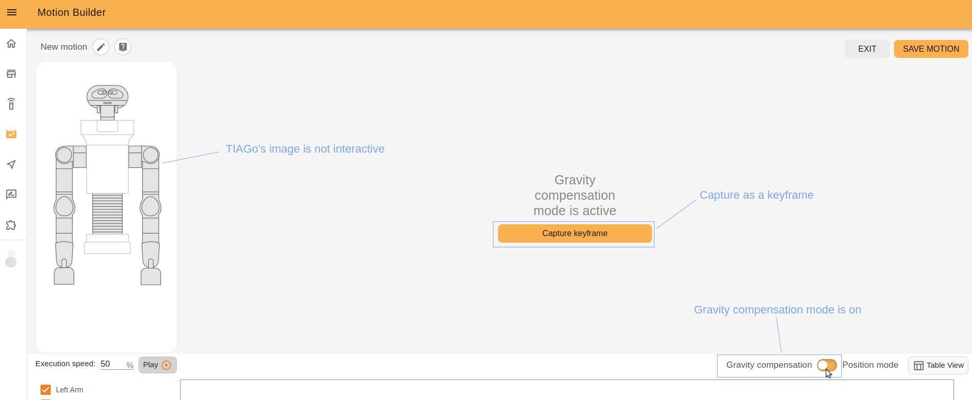
Note: The Gravity compensation mode is only available in robots that have an arm.
14.8.10 Timeline
After creating a new keyframe it will appear graphically on the timeline as a pointer. If the pose of any joints group was changed, opposite the corresponding checkbox will appear a colored line. The colors match with the color of the joints group on TIAGo++’s image. For example, orange for the head, green for the right arm, blue for the left arm.
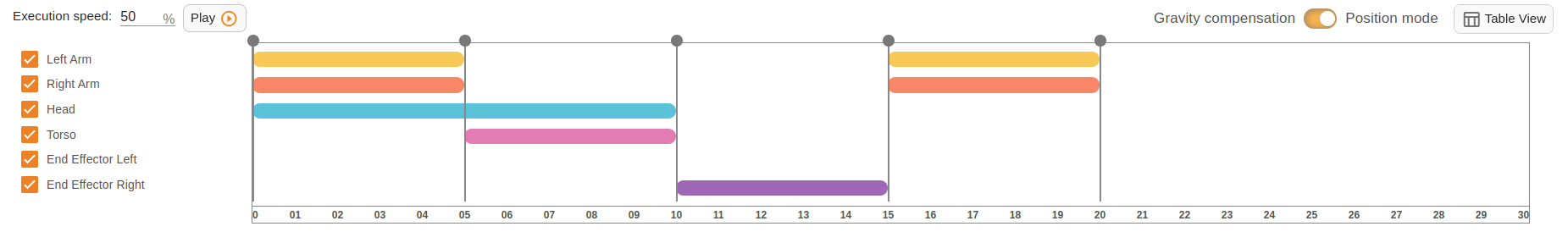
Each pointer is a keyframe you captured. It is situated on the timeline relatively to the time the robot needs to implement the motion. By dragging you can move the keyframe on the timeline.
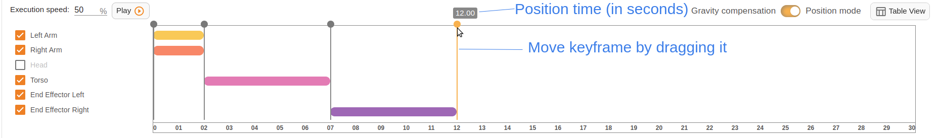
By double clicking you can open a context menu of the selected keyframe.
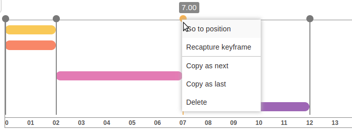
Go to position - robot will move to the captured position.
Recapture keyframe - the selected keyframe will be replaced with the current pose of the robot.
Copy as next - copy this keyframe right after it.
Copy as last - add copy to the end of the motion.
Delete - delete one keyframe.
14.8.11 InfoTable
The timeline has another view mode - infotable. Here you can see detailed info about each keyframe: how long this keyframe lasts (in seconds) and angular position of each joint in radians.
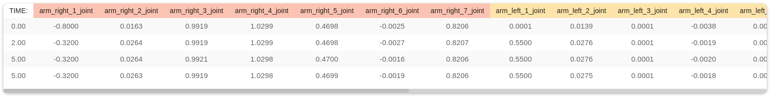
To change the view click a ‘table” icon near the “Play” button.
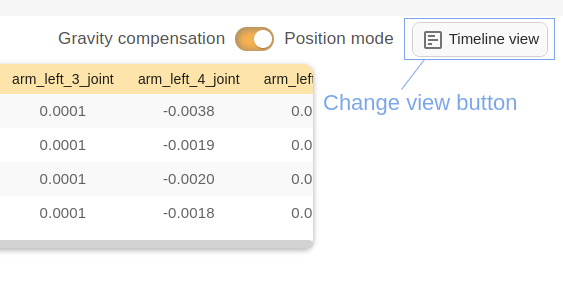
14.8.12 Speed of the execution
Speed number allows to control the speed of the motion execution. Switch to 100% to execute the motion at full speed, reduce it to slow down the motion.
Note: the speed is ONLY reduced while in Editor mode, when playing the motion from the homepage or another webapp like 14.6 Command desks, it will play at 100% speed in accordance with the timeline.
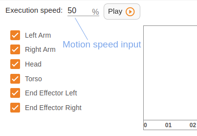
14.8.13 Play motion
You can play motion while editing or after it. To play motion from the Editor click the “Play” button under TIAGo++’s image.
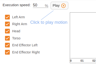
If you want to play the motion from the start page, click the “play” icon of the chosen motion.
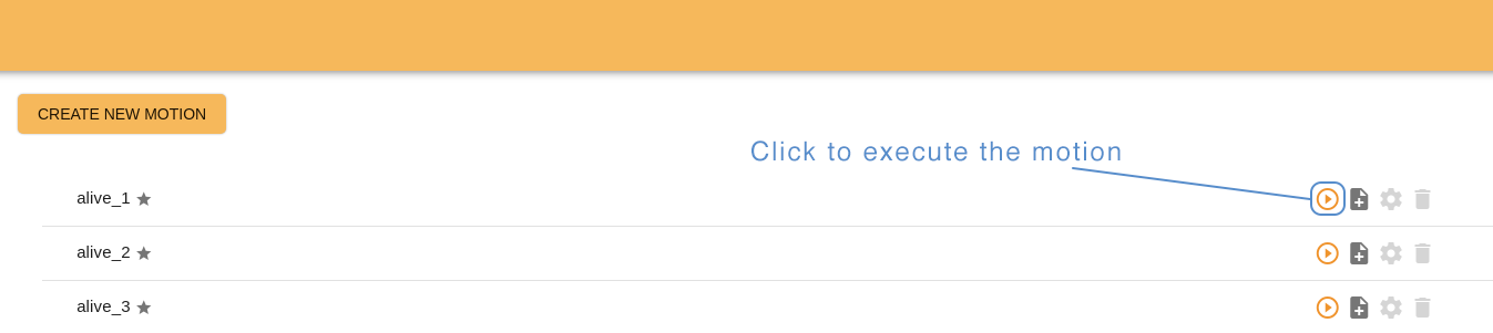
Also you can play motions from Command desks webapp. Open the “Motions” desk and click the corresponding button.
TIAGo++’s touchscreen allows play motions as well. Create a page with buttons using “Page with buttons” or “Slideshow” template and assign any motion to the button on the screen. When a user touches this button, TIAGo++ will execute the motion.
14.8.14 Save motion
To leave the Editor without saving the changes click “EXIT”, to store the changes and leave click “SAVE MOTION”. Remember that the ROS name is a required field. Fill it before saving a motion and leaving Editor.

14.9 Visual Programming
14.9.1 What is a Visual Programming webapp?
Visual programming is a WebGUI application that allows you to create and execute robot programs. The main advantage of Visual Programming is the user friendly interface. So, you can create programs with minimal technical skills.
To access the Visual Programming select the puzzle icon in the left menu bar of webGUI.
14.9.2 Interface
Visual Programming webapp consists of a homepage with a list of previously created programs and a visual editor for creating and editing programs.
14.9.3 Homepage
The homepage serves to store a list of all created programs, to manage them and to create new ones.
The interface of homepage has:
a button to create a new program,
a list of programs created earlier,
search engine (loupe icon) for quick navigation through the list.
Each program on the list has:
icon to start program execution.
icon to edit the program.
icon to create a copy of choosed program.
icon to remove the program.
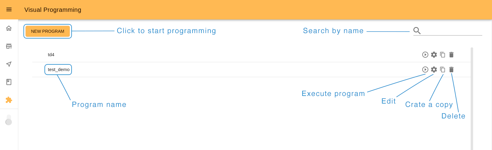
In case you clicked the Copy icon, the system will ask you to choose a new program name, because the program names should not be repeated. Be careful when choosing the name, as it cannot be changed later.
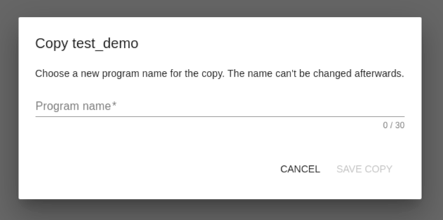
If you click the New Program button or the Edit icon, you will be redirected to the visual editor.
14.9.4 Editor
The visual editor is the main tool of this application. The interface consists of three sections: two columns with interactive blocks on the sides and a Workspace in the center.
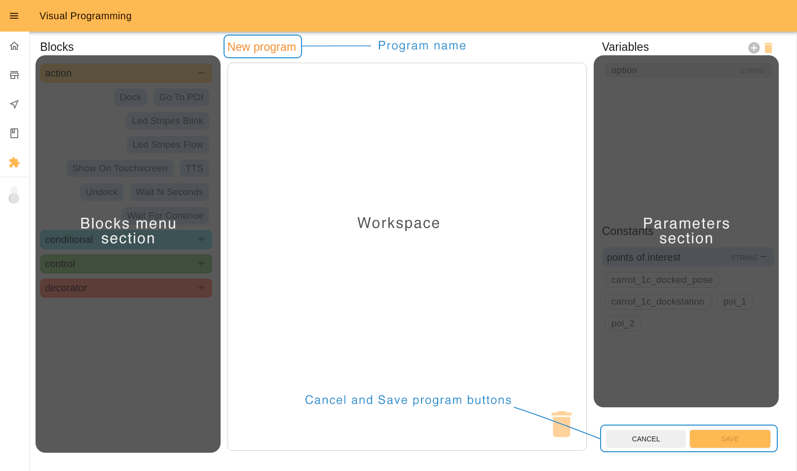
14.9.4.1 Blocks
Note: some blocks may be not available or can be different depending on the model of robot.
A program is a set of instructions that will be executed by the robot.
A block is an instruction in the program. There are four types of blocks used:
actions, which represent specific actions for the robot to do.
conditionals, which evaluate when a step should be executed.
controls, which allow modifications to the normal order of instructions and .
decorators, which modify how other instructions are performed, for example repeating them.
Blocks section is a menu of program blocks grouped by functions. By clicking on the group headers (with plus/minus icon), you can open or close the tab with the blocks in this group.
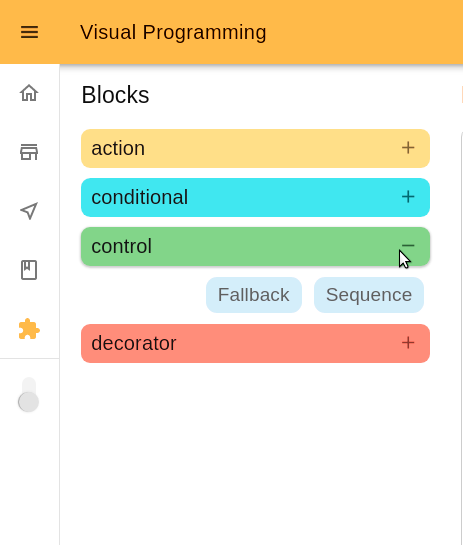
14.9.4.2 Workspace
The Workspace is an interactive area where you can create programs by adding blocks in the order of their execution. Programs are executed in sequential order, starting at the top.
Add a block to the Workspace
To add a block to the Workspace, drag it with the cursor or double-click on it. If you drag the block, the shadow on the Workspace will indicate where you can place it. In the case of double clicking on it, the block will be automatically added to the end of the queue.
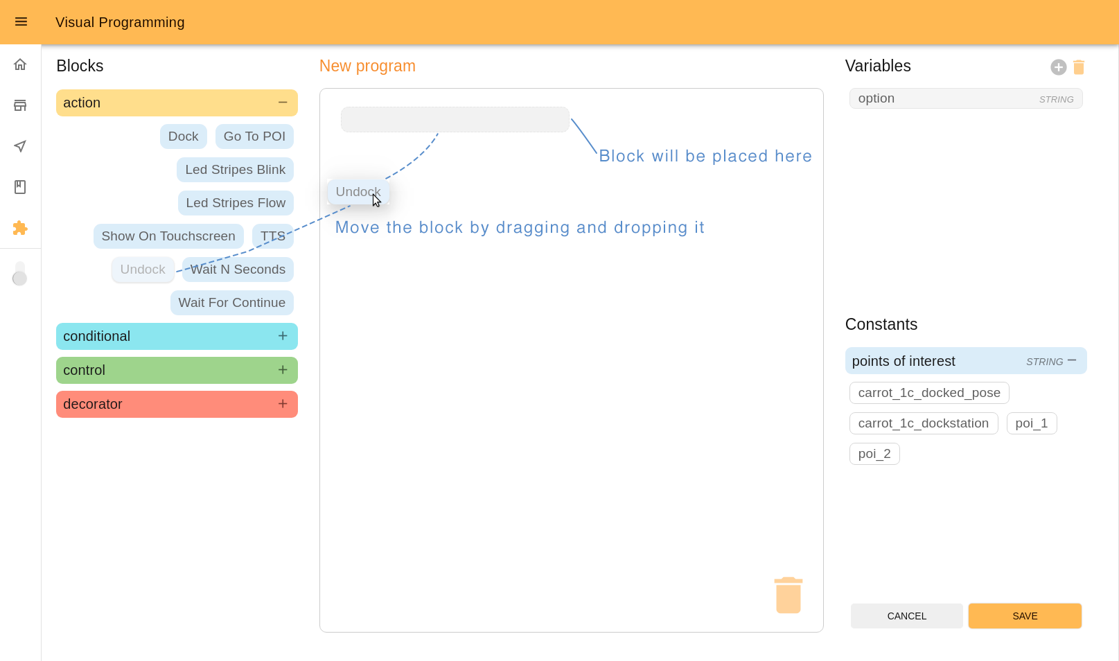
Move blocks inside the Workspace: Children blocks
To move blocks inside the Workspace drag it to the desired position.
Certain types of blocks may have children blocks, as indicated by the indentation. In the case of Conditionals and Controls children blocks will be executed or not according to the parent’s configuration. In the case of Decorators children blocks will see their behavior modified accordingly.
To find further information see the 14.9.7 Blocks library.
When you are dragging a block to the Workspace or inside it, look at the shadow that indicates you where you can move the block: under it, below it or as its child.
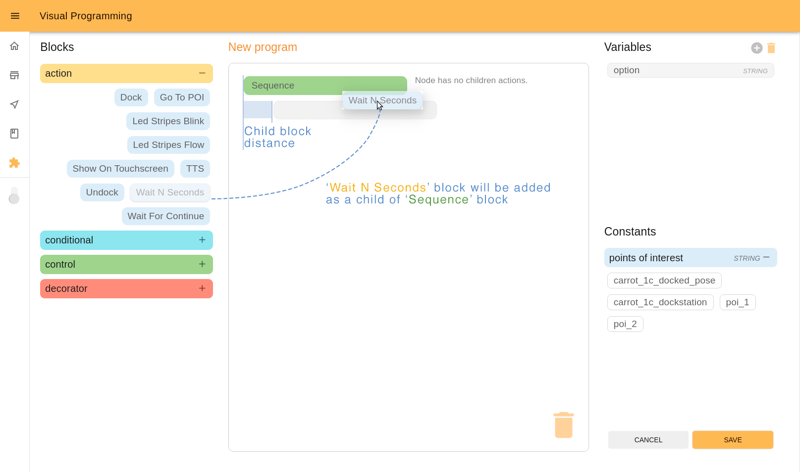
You can edit relations between parent and child blocks any moment during the editing process. To move the block, click an arrow icon on the left of it.
Delete blocks
To delete any block from the Workspace, drag it to the trash icon and drop it over the icon.
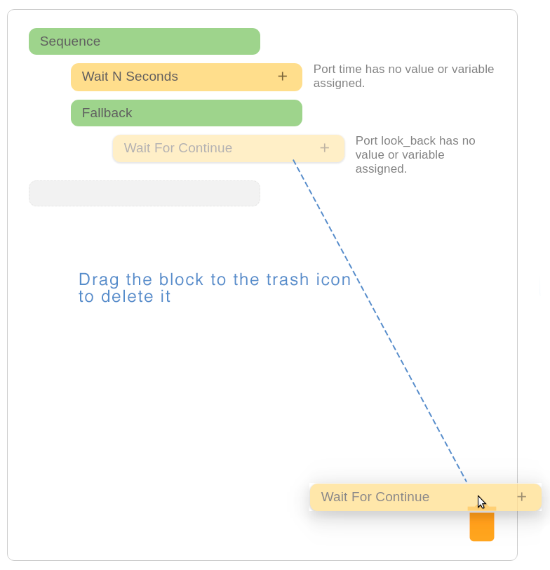
Blocks with ports
Blocks may have ports. It allows adding variables or constants from the right menu. Those ports represent parameters that set up how the action works or return values.
Also near the block you can see a short message that indicates what you should do. Grey text means that it is “a recommendation”, red text - it is a critical error you must resolve. Click the block with the ‘plus’ icon to open it.
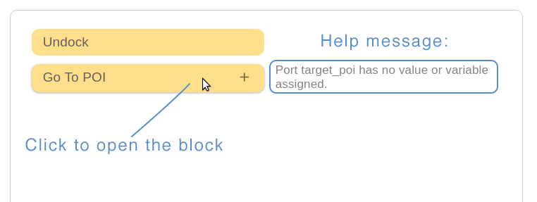
Ports are directional, that is a port is either read for Input ports, written to for output ports or both for in-out ports. Green arrows (or one arrow) between port name and port input indicate the direction of the port.
Ports also have a type, which means that they only accept certain types of data, for example text, or numbers. If you hover the cursor over the port you will see a tooltip with the port type.
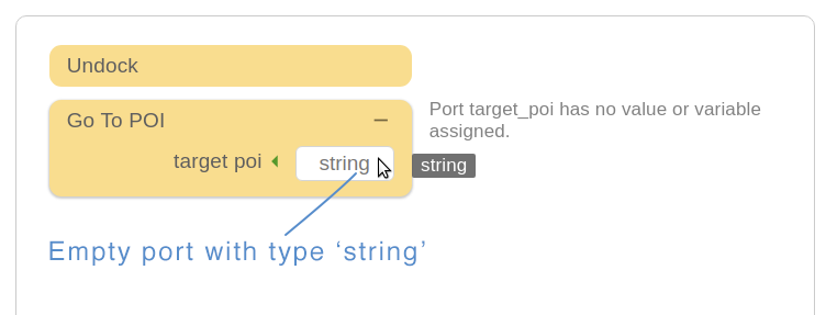
There are different ways to add a value to the port. First, is typing it manually.
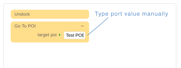
Second, by adding a variable from the right menu.
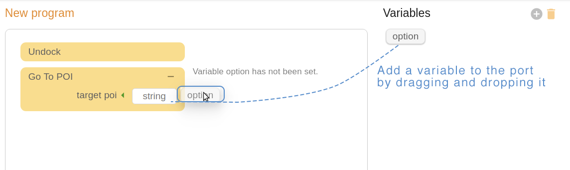
To delete the added variable from the port, click the ‘X’ icon near ir.
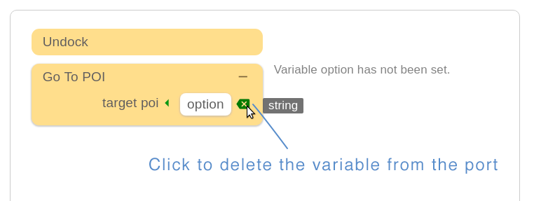
The third way to add value is by using constants. Drag and drop the constant you chose and it will convert to the text value of the port.
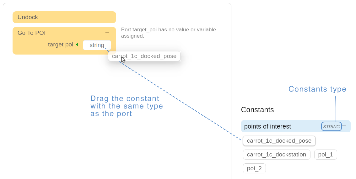
The result:
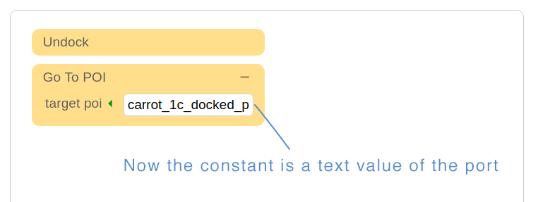
14.9.4.3 Variables
Variables are used to store information for the program. Usually they will be used first in an output port to store the result of an action and then used in input ports to be read. Variables are also typed.
To create a new variable, click the ‘Plus’ icon.
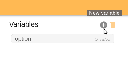
You will open a popup window where you should fill the Name and Type fields.
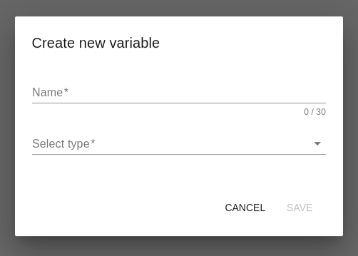
The name of the variable must start with a letter and can consist of only letters, numbers and ‘_’ symbol. Also it must not be repeated. In each case you will see an error message.
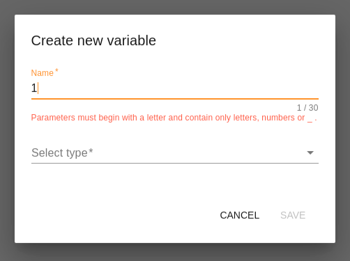
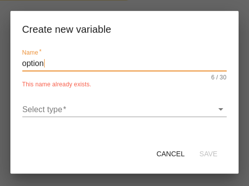
Click ‘Save’ to add a new variable to the list.
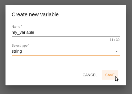
To delete a variable, active ‘Delete’ mode by clicking the ‘Trash’ icon.
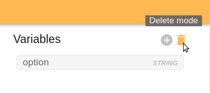
Choose the variable you want to delete.
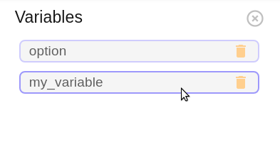
Confirm your choice.
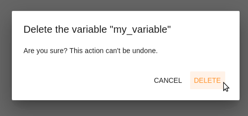
Confirm your choice.
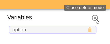
14.9.4.4 Constants
Constants are used to list values that may be of interest for the programmer, for example, existing POIs on the system.
Like the block menu, constants are grouped by type. In the example, we only have ‘string’ constants. If there is a lot, it is convenient to use opening and closing tabs.
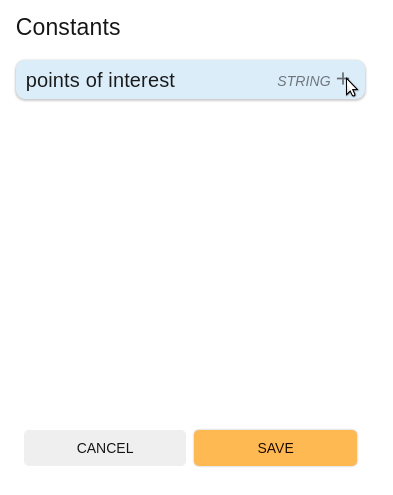
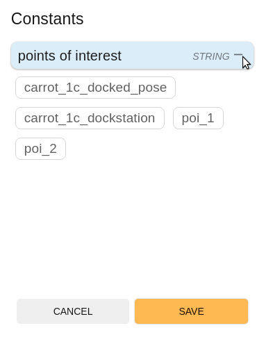
14.9.5 How to create a program?
14.9.5.1 Programming process
As it mentioned above, the program is a set of instructions that will be executed by the robot. Programs are executed in sequential order, starting at the top. A block is an instruction in the program. Check the 14.9.7 Blocks library before starting to know more which functions each block has.
So you should add blocks to the Workspace in the desired order and assign corresponding value to the block ports using variables or constants. Pay attention to the prompts on the Workspace. They indicate next steps or important errors.
14.9.5.2 Save program
To leave the edition process without storing changes, click the ‘CANCEL’ button in the lower right corner of the page.
To store your progress, click the ‘SAVE’ button and choose a name for your program. The name cannot be changed afterwards.
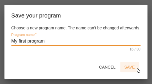
14.9.6 How to execute a program?
To execute the program go to the Visual Programming homepage and click the ‘Play’ icon of the chosen program.
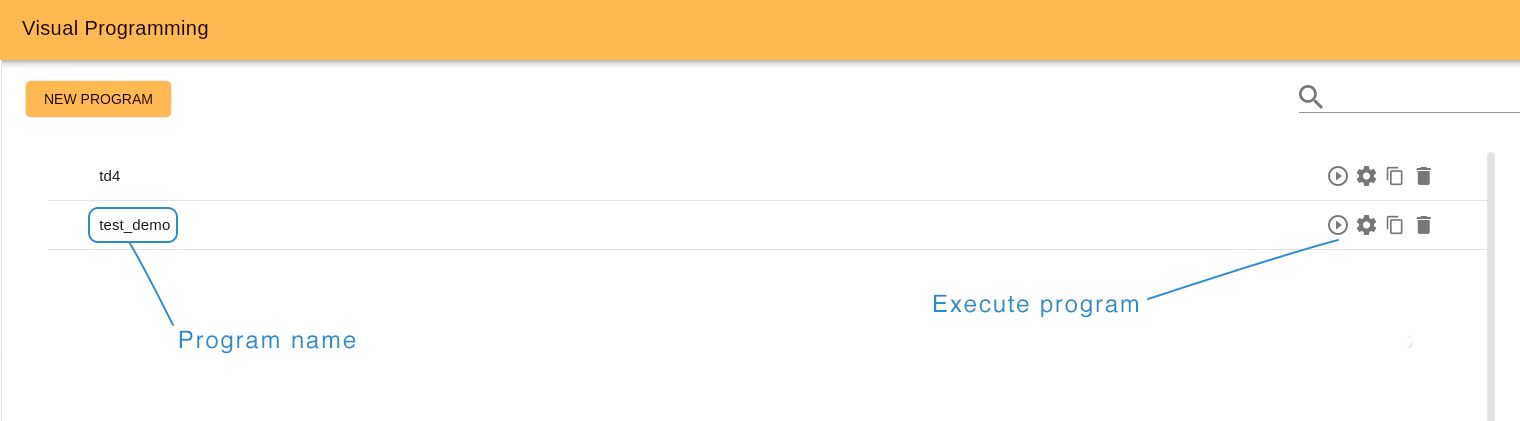
14.9.7 Blocks library
Note: some blocks may be not available or can be different depending on the model of robot.
14.9.7.1 Actions
Actions are executed by the robot and can either Succeed or Fail.

Different actions available

The dock action makes the robot connect to a dock station in front of it.

The Undock action will disconnect the robot from a dock station.

The Go To POI action instructs the robot to navigate to a POI in the current map. The action will SUCCEED when the robot reaches the target POI, if for any reason the robot is unable to reach the POI the action will FAIL.
target poi [String Input Port]: Name of the POI to navigate to.

The Led Stripes Blink action instructs the robot to blink the leds in the configured pattern for some time, switching back and forth between two colors.
effect duration [float Input Port]: Total duration of the effect.
first color [string Input Port]: Color in format R,G,B,A 255 (i.e. white is 255,255,255,255).
first color duration [float Input Port]: Duration of the first color.
second color [string Input Port]: Color in format R,G,B,A 255 (i.e. white is 255,255,255,255).
second color duration [float Input Port]: Duration of the second color.

The Show On Touchscreen action shows a list of buttons on the small TFT screen on the back of the TIAGo base, and then waits for a user to press one of the buttons.
options [string Input Port]: Comma-separated list of buttons to show on the TFT.
selected option [string Output Port]: The option selected by the user will be stored in this port.

The TTS action will make the robot speak a sentence.
text [string Input Port]: Text to be read by the robot.
lang [string Input Port]: Language code in which the robot should speak (i.e. en_GB for british english).

The Wait N Seconds action will halt the execution of the program for the configured amount of time.
time [unsigned int Input Port]: Number of seconds the robot should wait.

The Wait For Continue action will stop the robot until an external signal is sent.
look back [float Input Port]: if a signal was sent less than look back seconds ago the action will consider it valid and continue.
The Wait For Path action will stop the robot in place and wait until a path is available to the configured POI.
target poi [string Input Port]: POI to which the robot will try to trace a path.
14.9.7.2 Conditionals
Conditionals are used to redirect the program flow according to different conditions. Conditionals must be used in chains that start with an IF, have zero or more ELSE IFs and may finish with an ELSE block.


If the values of both ports match execute the children of this block.
value A [any Input Port]: A value to compare, it may be of any type, but both ports must have the same type.
value B [any Input Port]: B value to compare, it may be of any type, but both ports must have the same type.

If the values of both ports match execute the children of this block.
value A [any Input Port]: A value to compare, it may be of any type, but both ports must have the same type.
value B [any Input Port]: B value to compare, it may be of any type, but both ports must have the same type.

In case all the previous IF and ELSE IF blocks in the chain have failed, execute this block’s children.
14.9.7.3 Control
Controls modify the behavior of the program sequence.


Children of a Fallback block will be executed in order until one of them SUCCEEDS, and then it will SUCCEED. If no block SUCCEEDS then it will FAIL.

A Sequence block encapsulates a set of blocks, executing them in order until one of them FAILS, in which case it will FAIL. If all of them SUCCEED it will SUCCEED as well.
14.9.7.4 Decorator
Decorators modify how blocks behave on success and failure situations.


A Repeat block will repeat its children blocks in order a number of times, as long as they SUCCEED.
num cycles [integer Input Port]: Number of times to repeat the children blocks.

A Retry Until Successful block will keep executing its children actions in order until all of them SUCCEED, up to the configured number of times.
num attempts [integer Input Port]: Maximum number of tries, can be set to 0 to retry indefinitely.
14.10 Navigation WebGUI
The Navigation Web Plugin covers the user-robot interaction required for navigating the robot. It is composed of two different tabs: Navigate, which allows interaction with the current navigation stack; and Edit map, which allows configuration of the map and its objects.
14.10.1 Glossary
Throughout this chapter the following terms will be used:
Point of Interest (POI): A pose (position and orientation) in the map, identified by a name.
Point of Direction (POD): An orientation with respect to the map, identified by a name.
POI List: An ordered list of POIs and PODs.
Zone of Interest (ZOI): An area in the map identified by a name.
Ramps (RA): An area on the map which contains a ramp (change in ground level).
Virtual Obstacle (VO): An area in the map marked as an obstacle for the robot, to prevent the robot from navigating in said area.
Highway (HW): A prefered path for the robot, described as a polyline.
Draw on map: Online editor that allows updating the map through drawing polygons and polylines directly in the map canvas.
14.10.2 Navigate tab
The Navigate tab contains all the required tools to properly navigate the robot in its current environment.
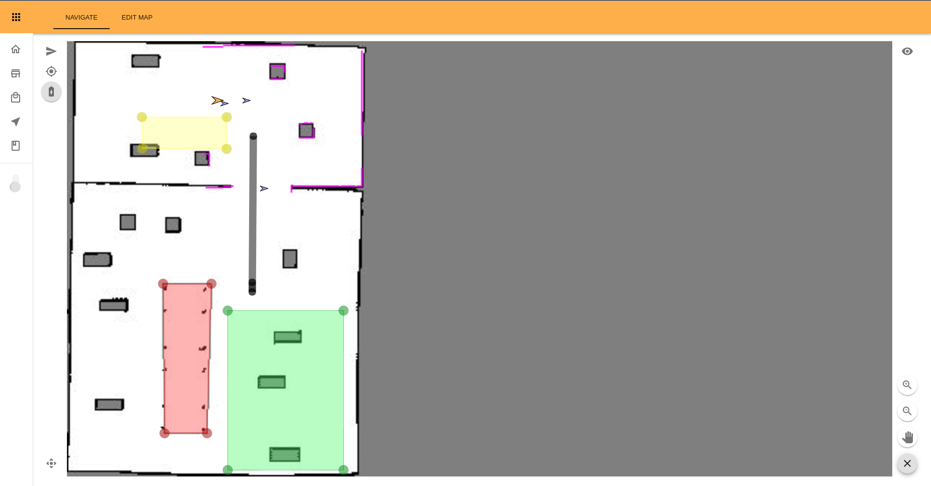
Figure: Example of the Navigate tab
The main component of the Navigate tab is the map in the center. On this map are displayed:
the robot as a pulsing orange arrow
the laser scan in pink
POIs as blue arrows
PODs as yellow arrows
ZOIs as green polygons
Ramp Areas as yellow polygons
VOs as red polygons
Highways as black polylines
The map may be zoomed in and out by using the scroll wheel of the mouse. When the map is zoomed in, it can be moved by dragging it with the mouse wheel.
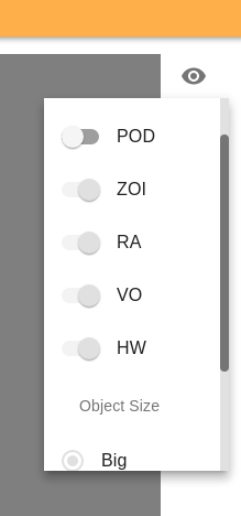
Figure: Detail of the view menu opened
To display the name of an object (POI, POD, ZOI, RA, VO or Highway) hover the mouse above it for the label to appear. If multiple objects are overlaid the name of each object will appear as well as its type.
On the top left menu there are three buttons: Send To, Dock/Undock and Localize Robot.
The Send To button (represented with an arrow head) opens a popup to allow the user to choose a POI to send the robot to, or alternatively to select a point in the map. Selecting a point in the map is done by pressing down the left mouse button on the desired location and then dragging the mouse to select the target orientation.
The Localize robot button (represented with a target icon) allows the user to change the current localization of the robot on the map. In order to do so a position must be selected by pressing down the left mouse button on the desired location and then dragging the mouse to define the target orientation. The robot position will then be updated to match the selected configuration.
The Dock/Undock button (represented with a battery) allows the user to either dock to a dock station or undock from it, depending on the current state of the robot. When the robot is docked the button has a grey background and a lighting bolt drawing on it, otherwise the battery icon is empty and has a white background.
The eye icon on the top right opens a menu to change the displayed objects and change their size as shown on Figure: Detail of the view menu opened. Each type of object has a toggle to show or hide them, and their size can be changed between Small, Medium and Big (the default being Big).
On the lower left the Joystick button (represented with a movement icon) allows the user to open and close a small joystick to control the robot.
The mouse icon on the lower right side opens a menu, shown in figure below, to change the zoom by clicking the zoom in and zoom out icons, and to activate drag mode by clicking on the hand icon. Isn drag mode the map can be panned by clicking and dragging with the left mouse button. The menu can be closed by clicking on the x icon, which automatically disables drag mode if it was enabled.

Figure: Icons on the zoom menu.
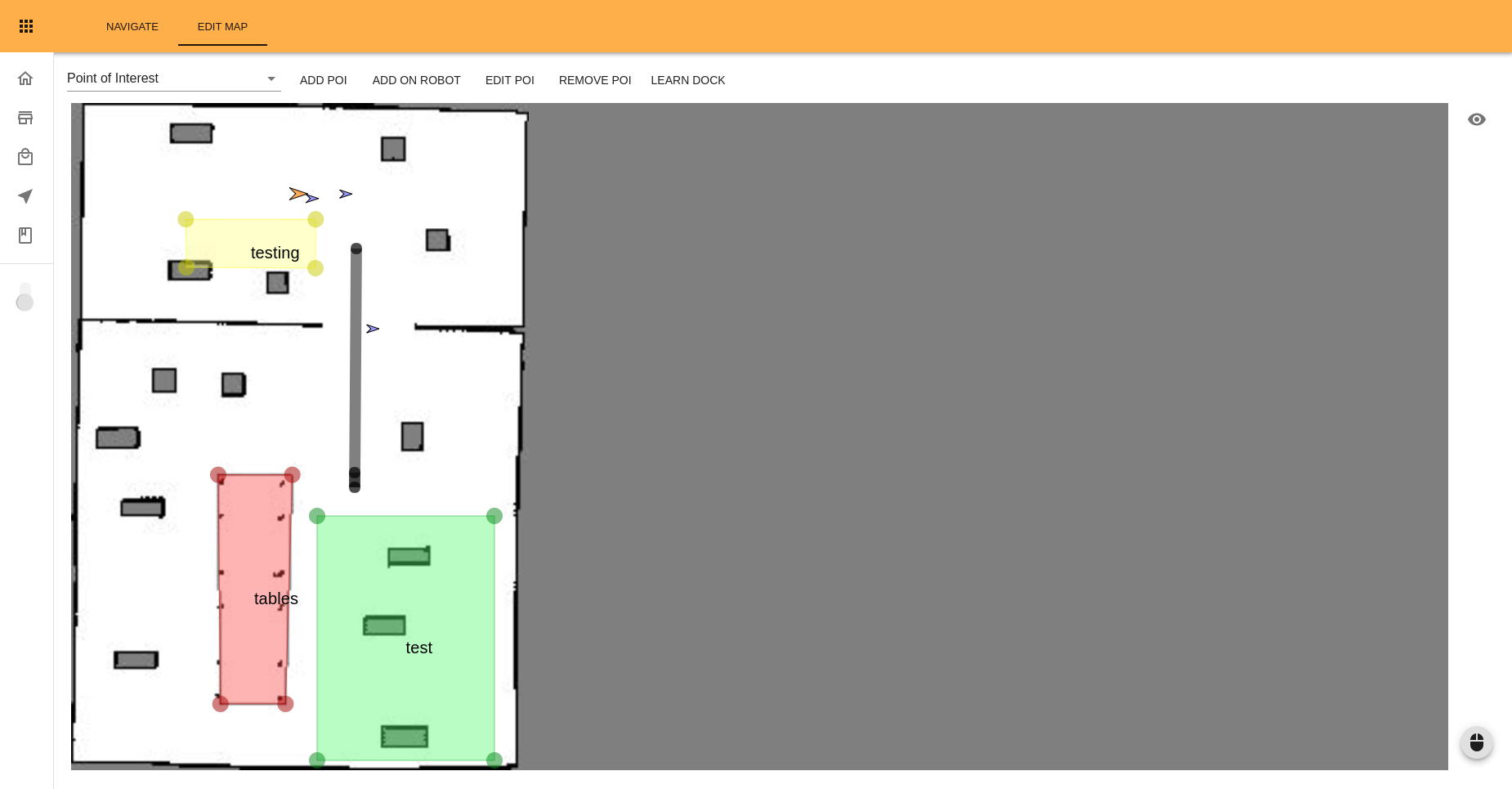
Figure: Example of the Edit Tab
14.10.3 Edit Map tab
Similarly to the Navigate tab the main component of this tab is the map shown in the center of the page. The map displays the same objects as in the Navigate tab (the laser is not displayed, however) and can be zoomed in and out, and moved, in the same way. Objects may be hidden or shown, and their size changed as explained in the Navigate tab. The mouse controls menu is also accessed and used in the same way.
On the top left menu a dropdown list is displayed, with options to edit the different objects. By selecting the appropriate tab of object in this combo, the appropriate buttons will be shown, allowing users to add, edit and remove the respective type of object.
Point of Interest
When selecting Point of Interest in the dropdown five buttons are displayed: Add POI, Add On Robot, Edit POI, Remove POI, and Learn Dock.
The Add POI button allows the user to select a position to create a new POI. Selecting a position is done by pressing down the left mouse button on the desired location and then dragging the mouse to select the orientation of the POI. Once this is done a popup will open to allow the user to set the name of the new POI. Pressing the Create button saves the POI, pressing Cancel discards the changes made.
The Add On Robot button creates a POI at the current location, with the current orientation, of the robot. When clicked a popup will appear to allow the user to set the name of the new POI. Pressing the Create button saves the POI, pressing Cancel discards the changes made.
The Edit POI button allows the user to modify an existing POI. First the user should double click on an existing POI to indicate which POI will be modified. A popup will open that allows the user to change the name, move or rotate the POI. Clicking the Move button allows the user to drag and drop the POI on the map. Clicking the Rotate button allows the user to rotate it, by pressing down the left mouse button and dragging it on the map. Finally, pressing on the Done button stores the changes made on the POI, while pressing the Cancel button discards those changes. In order to exit the editing mode the user has to click on the Stop Editing button.
The Remove POI button allows the user to completely remove an existing POI. The user should double click the POI to be removed, which will prompt a popup asking the user for confirmation. This action can’t be undone.
Finally, the Learn Dock button triggers a learn dock behavior on the robot. The robot will attempt to dock on a dock station in front of it. If succesful, it will create the dock station and docked_pose POIs used in the docking system.
Point of Direction
When selecting Point of Direction in the dropdown three buttons are displayed: Add POD, Edit POD, and Remove POD. The three buttons work exactly like their POI counterparts.
POI Lists
When selecting POI Lists in the dropdown four buttons are displayed:
The Add POI List button allows the creation of a new POI List. First the name must be introduced in the new popup. Then the Edit POI List popup will be opened with the newly created list preselected.
The Visualize POI List button opens a popup to visualize an existing POI list. Once a list has been selected on the popup all other POIs and PODs will be hidden and the POIs in the POI list will turn red following the sequence marked by the POI List. To exit this visualization click on the Stop Visualization button. To edit the visualization speed use the eye icon on the top right corner of the screen. You will see the possible speed options: Low, Medium and High. After choosing the desired speed, the visualization of POIs will start from the beginning.
The Edit POI List button opens a popup to edit an existing list. On the first step an existing list must be chosen on the dropdown menu, On the second step the popup will show the list of POIs in the POI list on the right side, and a menu to select POIs and PODs on the right hand side, as shown in Figure Figure: Edit POI List popup. To add a new POI or POD to the list it can either be dragged and dropped to its position on the list, or double-clicked to be appended at the end of the list. To reorder the points on the list they can be dragged and dropped to their new position, or outside of the list to be removed from it. Points can also be removed from the list by clicking on the x icon next to them.
The Remove POI List button allows the user to completely remove an existing POI List. The user should select the POI List to be removed on the dropdown menu of the popup that will be shown, which will prompt a popup asking the user for confirmation. This action can’t be undone.
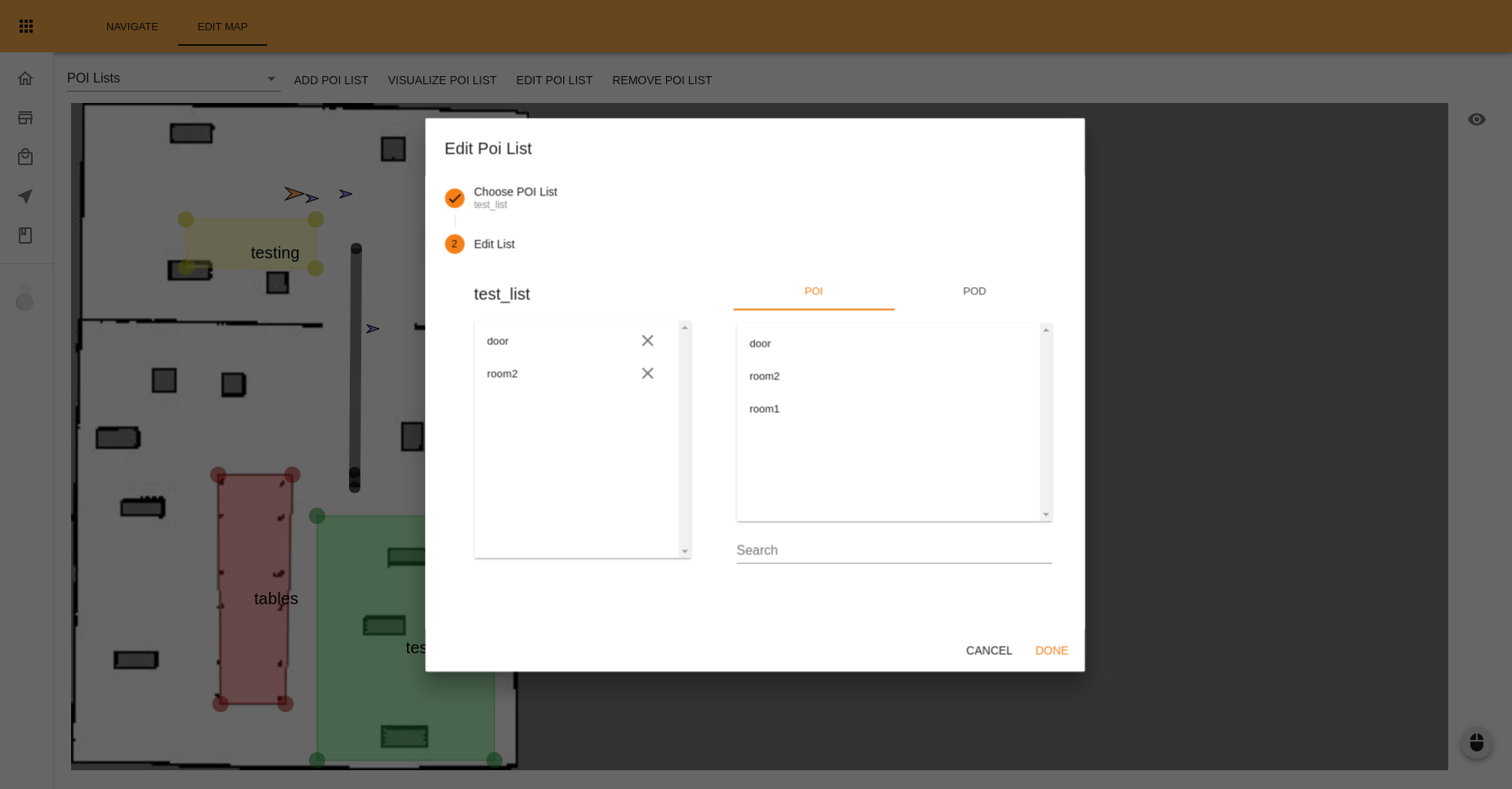
Figure: Edit POI List popup
Zone of Interest
When selecting Zone of Interest in the dropdown three buttons are displayed: Add ZOI, Edit ZOI, and Remove ZOI.
The Add ZOI button allows the user to draw a new zone. The zone is drawn by clicking with the left mouse button and then dragging, to create a basic rectangle shape of the desired dimensions. Once this is done, the vertexes can be dragged and dropped into position, and new vertexes can be added by clicking anywhere along the edges. When done, double-click on the green area to open the creation popup in order to set the name of the ZOI. Clicking on the Create button adds the new zone, clicking on the Cancel button discards the changes.
The Edit ZOI button allows the user to modify an existing zone. First the user should double click on the desired zone to be edited. A popup will open that allows the user to change the name of the zone. Clicking the Change Shape button allows the user to modify the shape of the selected zone. In this case, the vertexes can be dragged and dropped into position, and new vertexes can be added by clicking anywhere along the edges. Double clicking on the green area brings the editing popup back. Clicking on the Done button stores the changes made, clicking on the Cancel button discards the changes.
The Remove ZOI button allows the user to completely remove an existing ZOI. The user should double click the ZOI to be removed, which will prompt a popup asking the user for confirmation. This action can’t be undone.
Ramp Area
Important
While the robot can navigate on ramps with an inclination smaller than 12%, the robot has been designed for, and should be used in flat surfaces.
When selecting Ramp Area on the dropdown three buttons are displayed Add Ramp Area, Edit Ramp Area, and Remove Ramp Area.
The Add Ramp Area button allows the user to draw a new ramp. The ramp is drawn by clicking with the left mouse button and then dragging, to create a basic rectangle shape of the desired dimensions. Once this is done, the vertexes can be dragged and dropped into position, and new vertexes can be added by clicking anywhere along the edges. When done, double-click on the yellow area to open the creation popup in order to set the name of the Ramp Area. Clicking on the Create button adds the new ramp, clicking on the Cancel button discards the changes.
The Edit Ramp Area button allows the user to modify an existing ramp. First the user should double click on the desired ramp to be edited. A popup will open that allows the user to change the name of the ramp. Clicking the Change Shape button allows the user to modify the shape of the selected ramp. In this case, the vertexes can be dragged and dropped into position, and new vertexes can be added by clicking anywhere along the edges. Double clicking on the yellow area brings the editing popup back. Clicking on the Done button stores the changes made, clicking on the Cancel button discards the changes.
The Remove Ramp Area button allows the user to completely remove an existing Ramp Area. The user should double click the Ramp Area to be removed, which will prompt a popup asking the user for confirmation. This action can’t be undone.
Virtual Obstacle
When selecting Virtual Obstacle in the dropdown three buttons are displayed: Add VO, Edit VO, and Remove VO. The three buttons work exactly like their ZOI counterparts. While correctly localized, the robot will never create a path that goes through a VO, and cannot be localized inside of one.
Highways
When selecting Highways on the combo three buttons are displayed: Add Highway, Edit Highway, and Remove Highway.
The Add Highway button opens a popup to input the name and width of the new Highway. Clicking on the Draw button starts the drawing of the new highway. Clicking anywhere on the map places the first vertex of the highway, and new vertexes can be added by moving the mouse and clicking on the next position. Clicking an existing vertex causes the highway to be completed, and brings back the creation popup. Clicking on the Create button adds the new highway, clicking on the Cancel button discards the changes.
The Edit Highway button allows the user to modify an existing highway. First, the user should double-click on the highway to be edited. A popup will open that allows the user to change the name and width of the highway. Clicking the Modify button allows the user to drag and drop the vertexes of the highway. Clicking on the Extend button allows the user to add new vertexes to the highway. To do that, first the user must click on either the first or the last vertex of the highway. The highway will then be extended from that point. Clicking anywhere on the map will add a vertex in the desired position, clicking on an existing vertex will finish the extension, bringing back the edit popup. Clicking on the Done button stores the changes, clicking on the Cancel button discards them.
The Remove Highway button allows the user to completely remove an existing Highway. The user should double click the Highway to be removed, which will prompt a popup asking the user for confirmation. This action can’t be undone.
Draw on map
The option Draw on map allows the user to edit the navigation map by drawing polygons and polylines directly on it. Once chosen “Draw on map”, it opens a submenu with four buttons: Add drawing, Edit drawings, Remove drawings and Apply changes.
The Add drawings button opens a popup with two steps you should fill before starting to draw.
Step One: choose what zone you want to draw (“Drawing type”). There are three possible options:
empty space (will be painted in white color)
unknown space (grey color)
occupied space that means some object on the map (black color)
Step two: choose which shape you will use to draw (“Drawing shape”). It can be a polygon (“Area”) or polyline (“Line”). The drawing process is similar to creation of ZOIs for Area and Highways for Line. After drawing the desired shape on the map, double click on it to save or change it. By clicking the Add drawings button you can draw multiple zones on the map.
The Edit drawings button allows editing the shape of some already drawn zones. Use it to achieve the desired accuracy. Click the Stop editing button to exit from the editing mode.
With the Remove drawings buttons the user can remove the undesired drawings before they are saved.
To update the map according to new drawn zones click the Apply changes button. Click accept on the confirmation popup to apply the changes. The editing mode will be closed automatically and the map will be updated. The updating process might take a while, please don’t reload the page until it is finished. The applied changes cannot be undone.
14.11 Building Manager
The Building Manager Web Plugin covers the management operations related both to buildings and maps. This Plugin is divided in three different sections: The Building Manager tab, which covers building management, The Map Manager tab, which covers map management and the Update Map tab, which allows modification and merging of existing maps and their updates.
14.11.1 Building Manager Tab
The Building Manager tab lists all existing buildings and allows operations such as Building Creation, edition and removal.
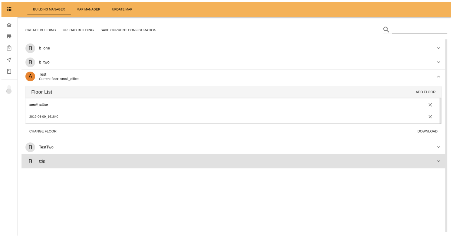
Figure: Manager Building Tab
The menu at the top left side displays three buttons:
The Create Building button opens a popup that allows the creation of a new building. Two steps are required to create a new building: assign a building name and choose a map for the first floor of the building. This map must contain the POIs for a dockstation (dockstation and docked_pose).
The Upload Building button opens a popup that allows the user to upload a building. Two steps are required: assign a name to the building that will be uploaded, and select a zip file on the user’s computer (which must have the same structure as that of the buildings downloaded through the Download button of a specific building).
The Save Current Configuration button stores the current WiFi configuration, as well as the current Task configuration on the building the robot is currently in (active building).
On the top right menu a Search field allows the user to filter the list of buildings by name.
The list of buildings shows the buildings configured on the robot. The currently active building is shown with an orange icon next to it. In addition the currently active floor is shown as well. Clicking on any of the buildings will expand the information shown on that building.
A list is shown with all the floors of the building, with the first floor of the building in bold, and the currently active floor, if any, initialized. At the top of the list the Add Floor button opens a popup with a dropdown menu to select another map to be added as a new floor to the building. Click on the cross next to each floor wil remove that floor from the building.
On the lower left-hand side either the Set As Current button is shown (if the building is not active), which opens a popup that allows the user to choose a floor on that building and then set that floor and that building as the currently active one; or the Change Floor button is shown (if the building is the active one), to choose a floor on that building to set as the currently active one.
In addition two other buttons are always shown on the lower right-hand side:
Download, which downloads the building configuration in zip format.
Remove, which allows the user to remove the building from the robot after a confirmation dialog (this action can be undone).
14.11.2 Map Manager Tab
The Map Manager tab lists all existing maps and allows operations such as starting a new map, uploading a new map or changing the currently active map.
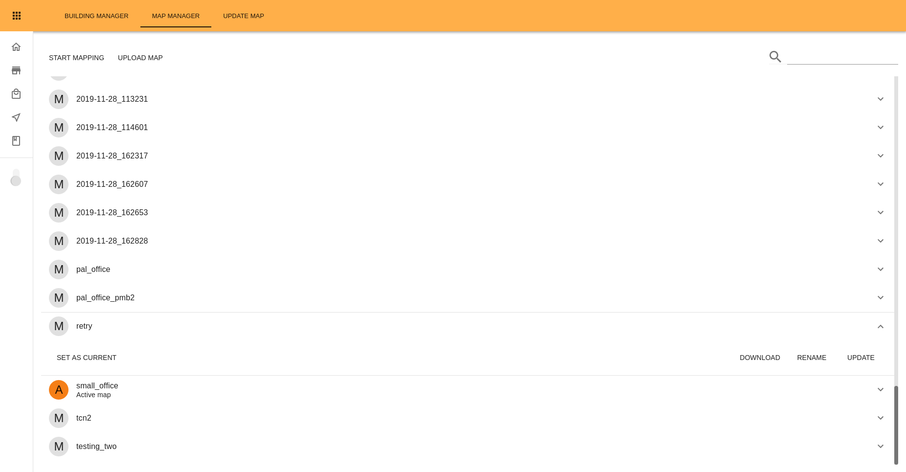
Map Manager Tab
The menu at the top left side displays two buttons:
The Start Mapping button will begin a new map, and change the screen to show a window around the robot with the map that is being created, as seen in Figure: Mapping screen. The Stop Mapping button shown on the top left menu stops the map and stores its information. After that a popup will appear to change the name of the newly generated map. Clicking on the minimap displayed at the top left corner of the mapping area will open a bigger version of the completed map. The eye icon on the top right side allows hiding or showing the minimap (which is shown by default). The joystick on the lower right side allows control of the robot.
The upload map button opens a popup that allows the user to select a zip file on his computer (which must have the same structure as that of the maps downloaded through the Download Map button), set up a name for the map and upload it on the robot.
On the top right menu a Search field allows the user to filter the list of maps by name.
The list of maps shows all existing maps on the robot. The currently active map is shown with an orange icon next to it. Clicking on any of the maps will expand the options on that map. If the map is not the active one the Set As Active button is shown in the lower left side, which will change the active map after a confirmation popup.
On the lower right side three buttons are shown:
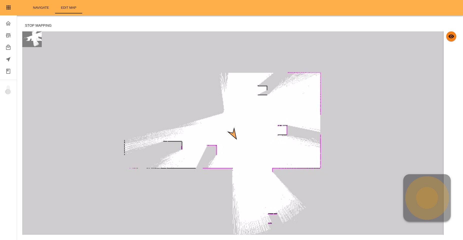
Figure: Mapping screen
The Download Map button downloads all the information of the map as a zip file.
The Rename Map button opens a popup to change the name of the map.
The Update button switches to the Update Map Tab with this map preselected as the Source Map.
14.11.3 Update Map Tab
The Update Map tab allows the user to visualize and apply updates to the maps loaded on the robot.
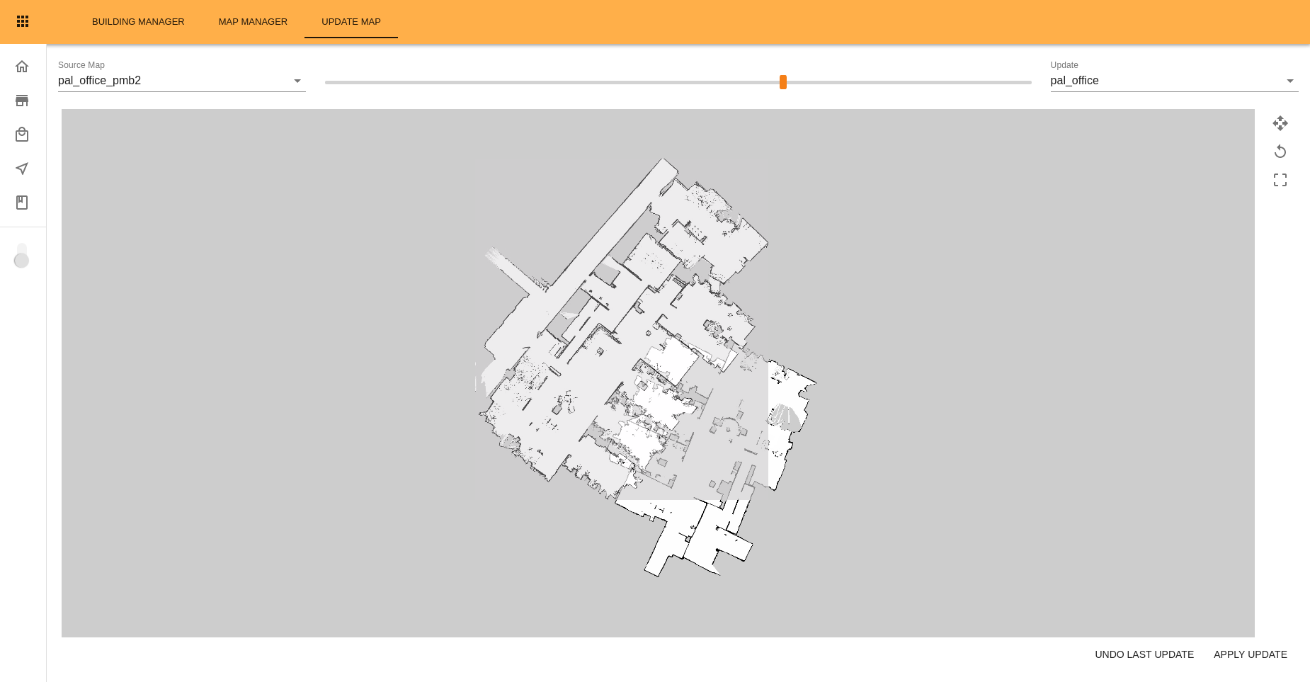
Example of the Map Updates Tab
On the top left side of the screen the Source Map dropdown list allows the user to select which of the available maps to work with. On the top right side the Update dropdown list allows the user to select which update or other map will be used to update the source map. In between both dropdowns a slider allows changing the transparency to visualize the differences. When the slider is at the right side only the updated version is displayed. Moving the slider to the left makes the updated version of the map transparent so differences can be seen, when the slider is at its left side only the original map is displayed.
The main component of the page shows both the source map with its update. The view can be zoomed in and out using the mouse wheel, and the view can be panned by drag-and-drop with the mouse wheel button.
At the right side of the map three buttons are displayed:
The Move Map button (represented with four arrows) activates the move mode. In this mode the updated map can be moved by dragging and dropping it with the left mouse button. When activating this mode the updated map will be made transparent so both maps can be seen. While in this mode the button will change to a tick icon, click on that button to exit move mode.
The Rotate Map button (represented with a circular arrow) activates the rotate mode. In this mode the updated map can be rotated around its center by clicking on the map with the left mouse button and then dragging it. While in this mode the button will change to a tick icon, click on that button to exit rotate mode.
The Update Area button (represented with a dashed square) allows the user to select a region to update. The area is drawn by clicking with the left mouse button and then dragging, to create a basic rectangle shape of the desired dimensions. Once this is done, the vertices can be dragged and dropped into position, and new vertices can be added by clicking anywhere along the edges. While in this mode the button will change to a tick icon, click on that button to exit update area mode.
Clicking on any of the other buttons while in a particular mode (i.e. clicking on the Rotate Map while in Move Map mode) will automatically change the mode.
At the bottom-right side of the page two buttons are shown:
The Undo Last Update button allows the user to undo the last update that was applied to the selected map (only the last update can be undone, additional clicks on the button won’t have any effect).
The Apply Update button will update either the selected area (if any), or apply all the Update to the Source Map, after a confirmation popup.
After a map update is performed it is possible that some of the existing POIs are now located inside, or too close, to an obstacle. In that event, a popup will appear warning the user about the fact, and the affected POIs will be displayed in red color in both the Map and Map Manager tabs, until those POIs are edited. The robot will still try to navigate to those POIs even if they are not edited, it will simply try to get as close as safely possible to the location and orientation of the POI.
15 Software architecture
15.1 Overview
The software provided in TIAGo++ is summarized in the next figure:
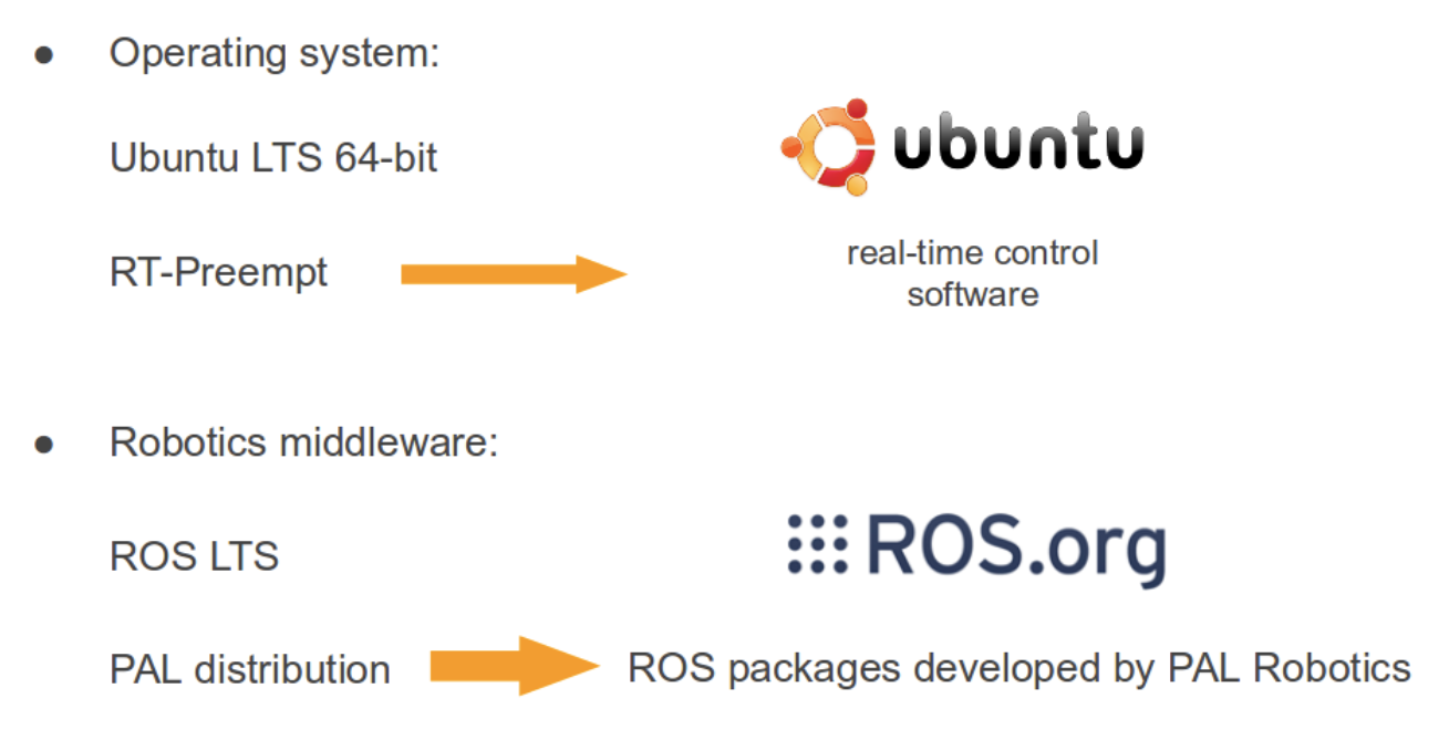
Figure: TIAGo++ software summary
15.2 Operating system layer
As can be seen, there are two main software blocks: the operating system, which is Ubuntu with the real-time kernel patch Xenomai, and the robotics middleware, which is based on Orocos for real-time, safe communication between processes.
15.3 ROS layer
ROS is the standard robotics middleware used in TIAGo++. The comprehensive list of ROS packages used in the robot are classified into three categories:
Packages belonging to the official ROS distribution melodic.
Packages specifically developed by PAL Robotics, which are included in the company’s own distribution, called ferrum.
Packages developed by the customer.
The three categories of packages are installed in different locations of the SSD, as shown in figure below. The ROS melodic packages and PAL ferrum packages are installed in a read-only partition as explained in 11.2 File system. Note that even if these software packages can be modified or removed, at the customer’s own risk, a better strategy is to overlay them using the deployment tool presented in 16 Deploying software on the robot. The same deployment tool can be used to install ROS packages in the user space.
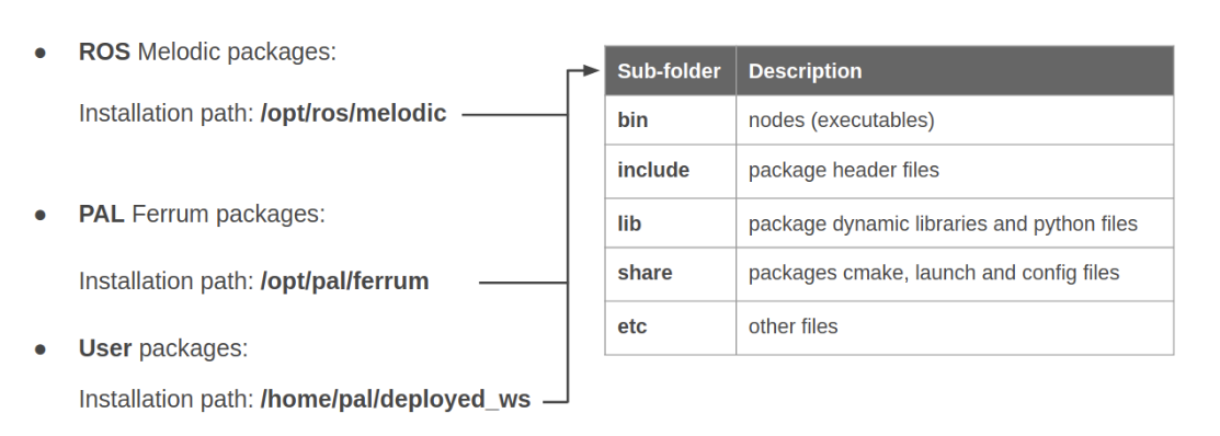
Figure: PAL Software overlay structure
15.4 Software startup process
When the robot boots up, the software required for its operation starts automatically. The startup process can be monitored in the WebCommander, as shown in the figure below.
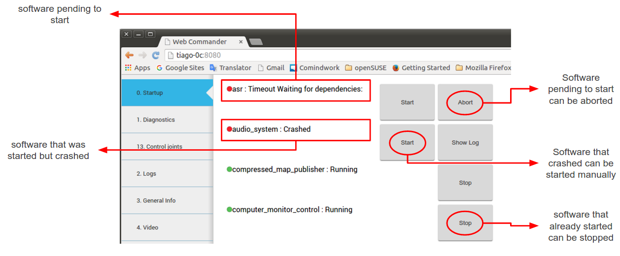
Figure: The startup tab displays the launched applications and their dependencies
16 Deploying software on the robot
This section contains a brief introduction to the deploy script PAL Robotics provides with the development environment.
The deploy tool can be used to:
Install new software onto the robot
Modify the behaviour of existing software packages by installing a newer version and leaving the original installation untouched.
16.1 Introduction
When TIAGo++ boots up it always adds two sources of packages to its ROS environment. One is the ROS
software distribution of PAL Robotics at /opt/pal/${PAL_DISTRO}/, the other is a fixed location at /home/pal/deployed_ws,
which is where the deploy tool installs to. This location precedes the rest of the software installation, making it possible to overlay previously installed packages.
To maintain consistency with the ROS release pipeline, the deploy tool uses the install rules in the CMakeLists.txt of every catkin package. Make sure that everything you need on the robot is declared to be installed.
16.2 Usage
usage: deploy.py [-h] [--user USER] [--yes] [--package PKG]
                      [--install_prefix INSTALL_PREFIX]
                      [--cmake_args CMAKE_ARGS]
                      robot
Deploy built packages to a robot. The default behavior is to deploy *all*
packages from any found workspace. Use --package to only deploy a single package.
positional arguments:   robot
                hostname to deploy to (e.g. tiago-0c)
optional arguments:
    -h, --help            show this help message and exit
    --user USER, -u USER  username (default: pal)
    --yes, -y             don't ask for confirmation, do it
    --package PKG, -p PKG deploy a single package
    --install_prefix INSTALL_PREFIX, -i INSTALL_PREFIX
                        Directory to deploy files
    --cmake_args CMAKE_ARGS, -c CMAKE_ARGS
                        Extra cmake args like
                        --cmake_args="-DCMAKE_BUILD_TYPE=Release"
e.g.: deploy.py tiago-0c -u root -p pal_tts -c="-DCMAKE_BUILD_TYPE=Release"
16.3 Notes
The build type by default is not defined, meaning that the compiler will use the default C++ flags. This is likely to include -O2 optimization and -g debug information, meaning that, in this mode, executables and libraries will go through optimization during compilation and will therefore have no debugging symbols. This behaviour can be changed by manually specifying a different option such as:
--cmake_args="-DCMAKE_BUILD_TYPE=Debug"Different flags can also be set by chaining them:
--cmake_args="-DCMAKE_BUILD_TYPE=Debug -DPCL_ONNURBS=1"If an existing library is overlayed, executables and other libraries which depend on this library may break. This is caused by ABI / API incompatibility between the original and the overlaying library versions. To avoid this, is it recommended to simultaneously deploy the packages that depend on the changed library.
There is no tool to remove individual packages from the deployed workspace except to delete the
/home/pal/deployed_wsfolder altogether.
16.4 Deploy tips
You can use an alias ( you may want to add it to your
.bashrc) to ease the deploy process:
alias deploy="rosrun pal_deploy deploy.py"
You can omit the
--user palas it is the default argumentYou may deploy a single specific package instead of the entire workspace:
deploy -p hello_world tiago-0c
You can deploy multiple specific packages instead of the entire workspace:
deploy -p "hello_world other_local_package more_packages" tiago-0c
Before deploying you may want to do a backup of your previous
~/deployed_wsin the robot to be able to return to your previous state, if required.
16.5 Use-case example
16.5.1 Adding a new ROS Package
In the development computer, load the ROS environment (you may add the following instruction to the ~.bashrc)
source /opt/pal/${PAL_DISTRO}/setup.bash
Create a workspace
mkdir -p ~/example_ws/src
cd ~/example_ws/src
Create a catkin package
catkin_create_pkg hello_world roscpp
Edit the CMakeLists.txt file with the contents in the figure below.
cmake_minimum_required(VERSION 2.8.3)
project(hello_world)

find_package(catkin REQUIRED COMPONENTS roscpp)

catkin_package()

include_directories(
    SYSTEM ${catkin_INCLUDE_DIRS}
)

## Declare a C++ executable
add_executable(hello_world_node src/hello_world_node.cpp)
target_link_libraries(hello_world_node ${catkin_LIBRARIES})

## Mark executables and/or libraries for installation
install(TARGETS hello_world_node RUNTIME DESTINATION ${CATKIN_PACKAGE_BIN_DESTINATION})
Edit the src/hello_world_node.cpp file with the contents in the figure below
 // ROS headers
 #include <ros/ros.h>

 // C++ std headers
 #include <iostream>

 int main(int argc, char** argv)
 {
   ros::init(argc,argv,"hello_world");

   ros::NodeHandle nh("~");

   std::cout << "Hello world" << std::endl;

   return 0;
 }
Build the workspace
cd ~/example_ws
catkin build
The expected output is shown in the figure below.
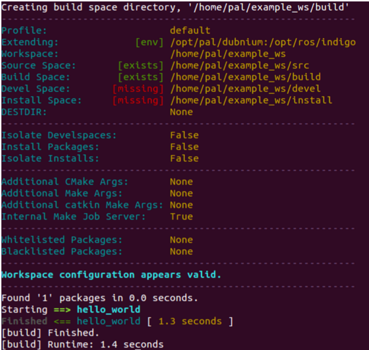
Figure: Build output of hello world package
Deploy the package to the robot:
cd ~/example_ws
rosrun pal_deploy deploy.py --user pal tiago-0c
The deploy tool will build the entire workspace in a separate path and, if successful, it will request confirmation in order to install the package on the robot, as shown in the figure below.
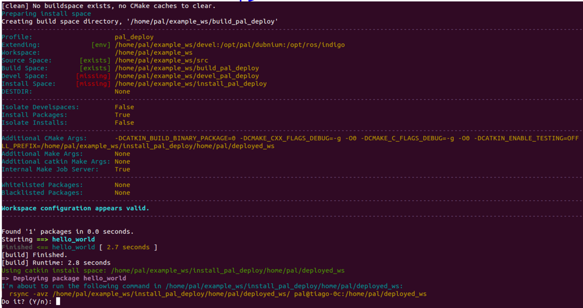
Figure: Deployment of hello world package
Press Y so that the package files are installed on the robot computer. The Figure: Installation of the hello world package to the robot shows the files that are copied for the hello world package, according to the installation rules specified by the user in the CMakeLists.txt.
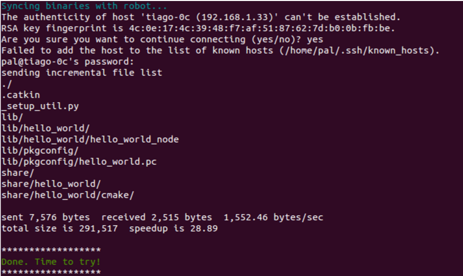
Figure: Installation of the hello world package to the robot
Then connect to the robot:
ssh pal@tiago-0c
And run the new node as follows:
rosrun hello_world hello_world_node
If everything goes well you should see ’Hello world’ printed on the screen.
16.5.2 Adding a new controller
One use-case for the tool is to add or modifiy controllers. Let’s take the ros_controllers_tutorials package, as it contains simple controllers, to demonstrate the power of deploying.
First, list the known controller types on the robot. Open a new terminal and execute the following:
export ROS_MASTER_URI=http://tiago-0c:11311
rosservice call /controller_manager/list_controller_types | grep HelloController
As it is a genuine installation, the result should be empty.
Assuming a running robot and a workspace on the development computer called tiago_dual_ws that contains the
sources of ros_controllers_tutorials, open a new terminal and execute the following commands:
cd tiago_dual_ws
catkin_make #-j5 #optional
source devel/setup.bash # to get this workspace into the development environment
rosrun pal_deploy deploy.py --package ros_controllers_tutorials tiago-0c
The script will wait for confirmation before copying the package to the robot.
Once successfully copied, restart the robot and run the following commands again:
export ROS_MASTER_URI=http://tiago-0c:11311
rosservice call /controller_manager/list_controller_types | grep HelloController
Now, a list of controller types should appear. If terminal highlighting is enabled, “HelloController” will appear in red.
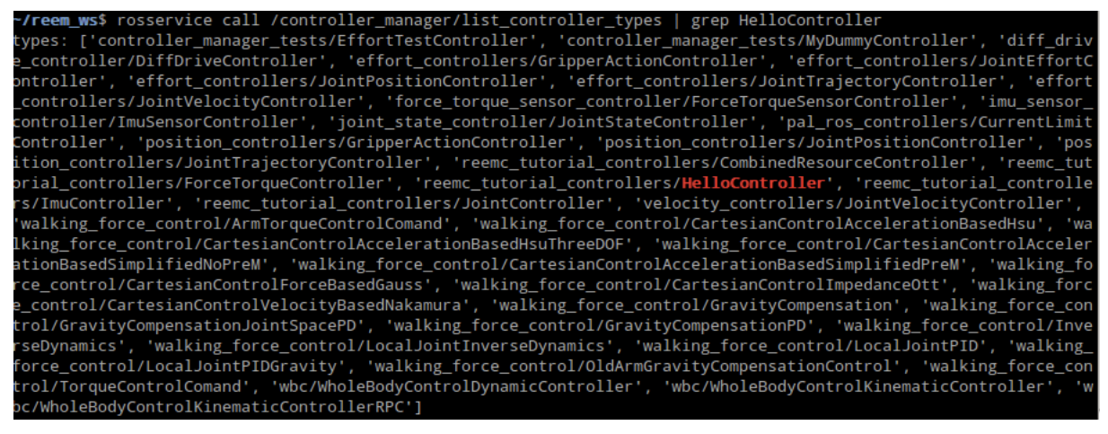
Figure: List of contoller types
16.5.3 Modifying an installed package
Now let’s suppose we found a bug on an installed controller inside the robot. In this case, we’ll change the joint_state_controller/JointStateController.
Go to , open a new terminal and execute the following commands:
cd tiago_dual_ws/src
git clone https://github.com/ros-controls/ros_controllers
# Fix bugs in controller
cd ..
catkin_make #-j5 #optional
source devel/setup.bash # to get this workspace into the development environment
rosrun pal_deploy deploy.py --package joint_state_controller tiago-0c
After rebooting the robot, the controller with the fixed changes will be loaded instead of the one installed in /opt/
17 Modifying Robot Startup
This section describes how the startup system of the robot is implemented and how to modify it, in order to add new applications, modify how they are launched, or prevent applications from being launched at all.
17.1 Introduction
TIAGo++ startup is configured via YAML files that are loaded as ROS Parameters upon robot startup.
There are two types of files: configuration files that describe how to start an application and files that determine which applications must be started for each computer in a robot.
All these files are in the pal_startup_base package within the config directory.
17.1.1 Application start configuration files
These files are placed inside the apps directory within config.
foo_bar.yaml contains a YAML description on how to start the application foo_bar.
roslaunch: "foo_bar_pkg foo_bar_node.launch"
dependencies: ["Functionality: Foo", "Functionality: Bar"]
timeout: 20
The required attributes are:
One of roslaunch, rosrun or bash: used to determine how to start the application. The value of roslaunch, rosrun or bash is the rest of the commands that you would use in a terminal (you can use bash magic inside such as ‘rospack find my_cfg_dir’). There are also some keywords that are replaced by the robot’s information in order to make scripts more usable. @robot@ is replaced by the robot name as used inour ROS packages (ie REEMH3 is reem, REEM-C is reemc, …)
dependencies: a list of dependencies that need to be running without error before starting the application. Dependencies can be seen in the Diagnostics Tab. If an application has no dependencies, it should be set to an empty list [].
Optional attributes:
timeout: applications whose dependencies are not satisfied after 10 seconds are reported as an error. This timeout can be changed with the timeout parameter.
auto_start: Determines whether this application must be launched as soon as its dependencies are satisfied, if not specified defaults to True.
Examples:
localization.yaml
roslaunch: "@robot@_2dnav localization_amcl.launch"
dependencies: ["Functionality: Mapper", "Functionality: Odometry"]
web_commander.yaml
rosrun: "pal_webcommander web_commander.sh"
dependencies: []
17.1.2 Computer start lists
The other type of YAML configuration files are the lists that determine what to start for each robot’s computer. They are placed within the config directory, inside a directory with the name of the computer that must start them, for instance control for the default computer in all of PAL Robotics’ robots, or multimedia for robots with a dedicated multimedia computer.
Each file contains a single YAML list with the name of the applications, which are the names of the YAML files for the application start configuration files.
Each file has a name that serves as a namespace for the applications contained within it. This allows the user to modify a subset of the applications to be launched.
Examples:
pal_startup_base/config/control/core.yaml
 # Core
- ros_bringup
- diagnostic_aggregator
- web_commander

 # Deployers
- deployer_xenomai

 # Navigation
- laser_ros_node
- map_server
- compressed_map_publisher
- map_configuration_server
- vo_server
- localizer
- move_base
- navigation_sm
- poi_navigation
- pal_waypoint

 # Utilities
- computer_monitor_control
- remote_shell_control
- rosbridge
- tablet_backend
- ros_topic_monitor
- embedded_networking_supervisor
17.1.3 Additional startup groups
Besides the control group, and the multimedia group for robots that have more than one computer, additional directories can be created in the config directory at the same level as the control directory.
These additional groups are typically used to group different applications in a separate tab in the WebCommander, such as the Startup Extras optional tab.
A startup_manager pal_startup_node.py instance is required to handle each startup group.
For instance if a group called grasping_demo is needed to a manage the nodes of a grasping demo started in the control computer, a directory will have to be created called grasping_demo containing at least one computer start list yaml file as described in the previous section.
Additionally it is recommended that we add to the control’s computer startup list a new application that will start the startup manager of the grasping_demo so it is available from the start.
rosrun: "pal_startup_manager pal_startup_node.py grasping_demo"
dependencies: []
17.2 Startup ROS API
Each startup node can be individually controlled using a ROS api that consists of the following services, where {startup_id} must be substituted for the name of the corresponding startup group (ie control, multimedia or grasping_demo).
/pal_startup_{startup_id}/start Arguments are app (name of the application as written YAML files for the application start configuration files) and args (optional command line arguments). Returns a string containing if the app was started successfully.
/pal_startup_{startup_id}/stop Arguments are app (name of the application as written YAML files for the application start configuration files). Returns a string containing if the app was stopped successfully.
/pal_startup_{startup_id}/get_log Arguments are app (name of the application as written YAML files for the application start configuration files) and nlines (number of lines of the log file to return). Returns up to the last nlines of logs generated by the specified app.
/pal_startup_{startup_id}/get_log_file Arguments are app (name of the application as written YAML files for the application start configuration files). Returns the path of the log file of the specified app.
17.3 Startup command line tools
pal-start This command will start an application in the background of the computer it is executed on, if it is stopped. Pressing TAB will list the applications that can be started.
pal-stop This command will stop an application launched via pal_startup in the computer it is executed on, if it is started. Pressing TAB will list the applications that can be stopped.
pal-log This command will print the name and path of the log file of the selected application. Pressing TAB will list the applications whose log can be seen.
17.4 ROS Workspaces
The startup system will look for packages in the following directories in order, if a package is found in one of the directories, it will not be looked for any further on directories lower in the list.
/home/pal/deployed_ws (see section 16 Deploying software on the robot)
/opt/pal/${PAL_DISTRO}
/opt/ros/${ROS_DISTRO}
17.5 Modifying the robot’s startup
In order to enable the robot’s users to fully customize the startup of the robot, in addition to using the files
located in the config directory of the pal_startup_base package, the startup procedure will also load all the parameters within /home/pal/.pal/pal_startup/ of the robot’s control computer, if it exists.
To modify the robot’s startup, this directory must be created and have the same structure as the config directory within the pal_startup_base package.
17.5.1 Adding a new application for automatic startup
To add a new application, “new_app”, to the startup, create a new_app.yaml file within the apps directory. Fill it with the information described in 17.1.1 Application start configuration files.
The file we created specifies how to start the application, in order to launch the application in the control computer, create a control directory and place it inside a new yaml file, which must consist of a list containing new_app.
For instance:
/home/pal/.pal/pal_startup/apps/new_app.yaml
roslaunch: "new_app_package new_app.launch"
dependencies: []
/home/pal/.pal/pal_startup/control/new_app_list.yaml
- new_app
17.5.2 Modifying how an application is launched
To modify how the application “foo_bar” is launched, copy the contents from the original foo_bar.yaml file in the pal_startup_base package and perform the desired modifications.
17.5.3 Adding a new workspace
In cases where the workspace resolution process needs to be changed, the file at /usr/bin/init_pal_env.sh can be modified to adapt the environment of the startup process.
18 Dockers inside the robot
This section describes how to install docker images inside the robot computer and run docker containers from the startup system.
18.1 Introduction
If you need to run software that cannot be installed in the same machine as the provided versions of OS or ROS, you can prepare a Docker image and start a container inside the robot with a controlled environment.
This section assumes that you know how docker works, you have prepared your docker image and you are ready to run it inside the robot.
18.1.1 The ros_docker_wrapper package
Make sure the ros_docker_wrapper package is installed in the robot, if not you may need to ask for a software upgrade.
If this package is installed, the docker packages should be installed and you should be able to run the command docker list to list the installed images, which is empty by default.
The docker images are stored in /home/pal/docker_dir so they are persistent between reboots. You should not need to modify this directory.
18.1.2 Installing new docker images
If the robot is connected to the internet, simply docker pull the image you need and it will be stored in the robot hard drive.
If the robot is not connected to the internet, or is unable to access your image for any other reason, you can download the image on a separate machine and copy it to the robot:
# From outside the robot
docker pull YOUR_IMAGE_NAME
# Save this image to a file
docker save -o YOUR_IMAGE_NAME.docker YOUR_IMAGE_NAME
# Transfer the file to the robot
scp YOUR_IMAGE_NAME.docker pal@tiago-0c:/tmp/
# Load the image in the docker daemon of the robot
docker load -i /tmp/YOUR_IMAGE_NAME.docker
18.1.3 Running containers
Standard docker commands can be used to run docker containers.
Additionally, ros_docker_wrapper has an executable script that executes docker run, this simplifies integration with other ROS tools.
For example: rosrun ros_docker_wrapper run_docker.sh --rm -it ros:noetic-robot bash
This script can be integrated in Chapter Startup section Modifying Robot Startup for automatic running of docker containers.
19 Sensors
This section contains an overview of the sensors included in TIAGo++, as well as their ROS and C++ API.
19.1 Description of sensors
Mobile base:
Laser range-finder. Located at the front of the base. This sensor measures distances in a horizontal plane. It is a valuable asset for navigation and mapping. Bad measurements can be caused by reflective or transparent surfaces.
Sonars. These sensors are capable of measuring from low to mid-range distances. In robotics, ultrasound sensors are commonly used for local collision avoidance. Ultrasound sensors work by emitting a sound signal and measuring the reflection of the signal that returns to the sensor. Bad measurements can be caused by either blocking the sensor (it will report max range in this case) or by environments where the sound signals intersect with each other.
Inertial Measurement Unit (IMU). This sensor unit is mounted at the center of TIAGo++ and can be used to monitor inertial forces and provide the attitude.
Head:
RGB-D camera. This camera is mounted inside TIAGo++’s head and provides RGB images, along with a depth image obtained by using an IR projector and an IR camera. The depth image is used to obtain a point cloud of the scene.
Stereo microphones. There are two microphones that can be used to record audio and process it in order to perform tasks like speech recognition.
Wrist:
Force/Torque sensor (optional). This 6-axis Force/Torque sensor is used to obtain feedback about forces exerted on TIAGo++’s end-effector.
Detailed specifications of the above sensors are provided in the 3 Specifications section .
20 Sensors ROS API
Note
Every node that publishes sensor data is launched by default on startup.
20.1 Laser range-finder
20.1.1 Topics published
/scan (sensor_msgs/LaserScan)
Laser scan data of the laser scanner.
20.2 Sonars
20.2.1 Topics published
/sonar_base (sensor_msgs/Range)
All measurements from sonars sensors are posted here as individual messages.
20.3 Inertial Measurement Unit
20.3.1 Topics published
/base_imu (sensor_msgs/Imu)
Inertial data from the IMU.
20.4 RGB-D camera
20.4.1 Topics published
/xtion/depth_registered/camera_info (sensor_msgs/CameraInfo)
Intrinsic parameters of the depth image.
/xtion/depth_registered/image_raw (sensor_msgs/Image)
32-bit depth image. Every pixel contains the depth of the corresponding point.
/xtion/depth_registered/points (sensor_msgs/PointCloud2)
Point cloud computed from the depth image.
/xtion/rgb/camera_info (sensor_msgs/CameraInfo)
Intrinsic and distortion parameters of the RGB camera.
/xtion/rgb/image_raw (sensor_msgs/Image)
RGB image.
/xtion/rgb/image_rect_color (sensor_msgs/Image)
RGB rectified image.
20.4.2 Services advertised
/xtion/get_serial (openni2_camera/GetSerial)
Service to retrieve the serial number of the camera.
/xtion/rgb/set_camera_info (sensor_msgs/SetCameraInfo)
Changes the intrinsic and distortion parameters of the color camera.
20.5 Force/Torque sensor
20.5.1 Topics published
/wrist_ft (geometry_msgs/WrenchStamped)
Force and torque vectors currently detected by the Force/Torque sensor.
21 Sensor visualization
Most of TIAGo++’s sensor readings can be visualized in rviz. In order to start the rviz GUI with a pre-defined configuration, execute the following from the development computer:
export ROS_MASTER_URI=http://tiago-0c:11311
export ROS_IP=10.68.0.128
rosrun rviz rviz -d `rospack find tiago_bringup`/config/tiago.rviz
Make sure to use your robot’s serial number when exporting the
ROS_MASTER_URI variable and to set your development computer’s IP
when exporting ROS_IP as explained in section 12.4 ROS communication with the robot.
An example of how the laser range-finder is visualized in rviz is shown in figure below.
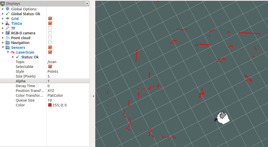
Figure: Visualization of the laser range-finder
Figure: Visualization of the RGB-D camera shows an example of visualization of the RGB image, depth image and point cloud provided by the RGB-D camera.
Finally, Figure: Visualization of force/torque sensor presents an example of force vector detected by the force/torque sensor.
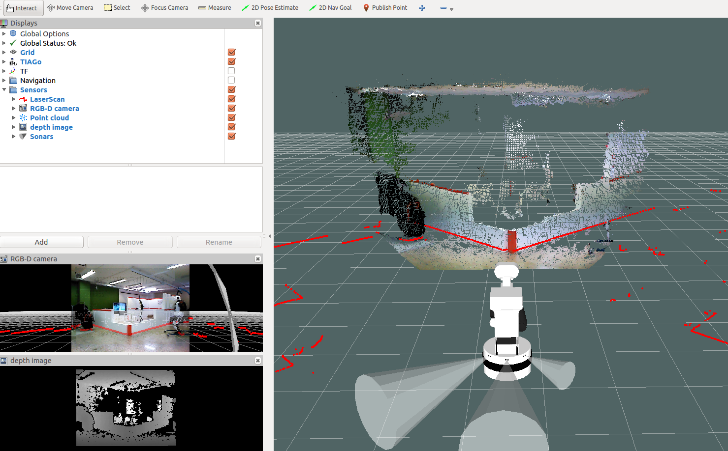
Figure: Visualization of the RGB-D camera
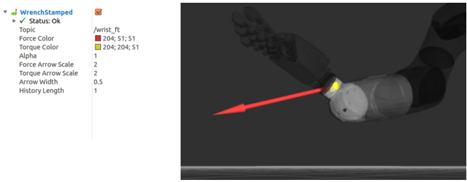
Figure: Visualization of force/torque sensor
22 Power status
This section contains an overview of the power-related status data reported by TIAGo++, as well as the ROS API and a brief description of the information available.
22.1 ROS API
The robot’s power status is reported in the /power_status ROS topic.
Note
This node is launched by default on startup.
22.2 Description
The following data is reported.
input: the voltage coming from the batteries.
charger: the voltage coming from the charger.
dock: the voltage coming from the dock station (not available with TIAGo++).
pc: the voltage coming from the PC.
charge: the percentage battery charge.
is_connected: whether TIAGo++ is currently connected to the charger.
is_emergency: whether the emergency stop button is currently enabled.
23 Text-to-Speech synthesis
23.1 Overview of the technology
TIAGo++ incorporates the Acapela Text-to-Speech from Acapela Group.
The technology used in this engine is the one that leads the market of synthetic voices. It is based on unit selection and allows to produce highly natural speeches in formal styles. The system is able to generate speech output, based on a input text utterance [1]. It does the phonetic transcription of the text, predicts the appropriate prosody for the utterance and finally generates the signal waveform.
Every time a text utterance is sent to the text-to-speech (TTS) engine it generates the corresponding waveform and plays it using TIAGo++ speakers. There are several ways to send text to the TTS engine: using the ROS API, by executing ROS commands in the command line or by implementing a client in C++. Each of them is described below.
23.2 Text-to-Speech node
23.2.1 Launching the node
To be able to generate speeches, the soundServer should be running correctly.
System diagnostics described in section 13 WebCommander allow to check the status of the TTS service runing in the robot. These services are started by default on start-up, so normally there is no need to start them manually. To start/stop them, the following commands can be executed in a terminal opened in the multimedia computer of the robot:
pal-start sound_server

pal-stop sound_server
23.2.2 Action interface
The TTS engine can be accessed via a ROS action server named /tts. The full definition and explanation
of the action is located in /opt/pal/${PAL_DISTRO}/share/pal_interaction_msgs/action/Tts.action, below is a summary of the API:
Goal definition fields:
I18nText text
TtsText rawtext
string speakerName
float64 wait_before_speaking
Result definition fields:
string text
string msg
Feedback message:
uint16 event_type
time timestamp
string text_said
string next_word
string viseme_id
TtsMark marks
Text to speech goals need to have either the rawtext or the text fields defined, as specified in the sections below.
The field wait_before_speaking can be used to specify a certain amount of time (in seconds) the system
has to wait before speaking aloud the text specified. It may be used to generate delayed synthesis.
Sending a raw text goal
The rawtext field of type TtsText has the following format:
string text
string lang_id
The rawtext field needs to be filled with the text utterance TIAGo++ has to pronounce and the text’s language
should to be specified in the lang_id field. The language Id must follow the format language_country
specified in the RFC 3066 document (i.e., en_GB, es_ES, …).
Sending a I18nText goal
The text field of type I18nText has the following format:
string section
string key
string lang_id
I18nArgument[] arguments
I18n stands for Internationalization, this is used to send a pair of section and key that identifies a sentence or a piece of text stored inside the robot.
In this case the lang_id and arguments fields are optional. This allows the user to send a sentence without
the need of specifying which language must be used, the robot will pick the language it’s currently speaking and say the sentence in that language.
In the ROS manual you can find examples about how to create an action client that uses these message definitions to generate a speech in TIAGo++.
23.3 Examples of usage
23.3.1 WebCommander
Sentences can be synthesized using the WebCommander, a text field is provided so that text can be written and then synthesized by pressing the Say button.
Additionally buttons can be programmed to say predefined setnences, see the 13.4.12 Commands Plugin Configuration for details.
Several buttons corresponding to different predefined sentences are provided in the lower part of the Demos tab, as shown in figure below.
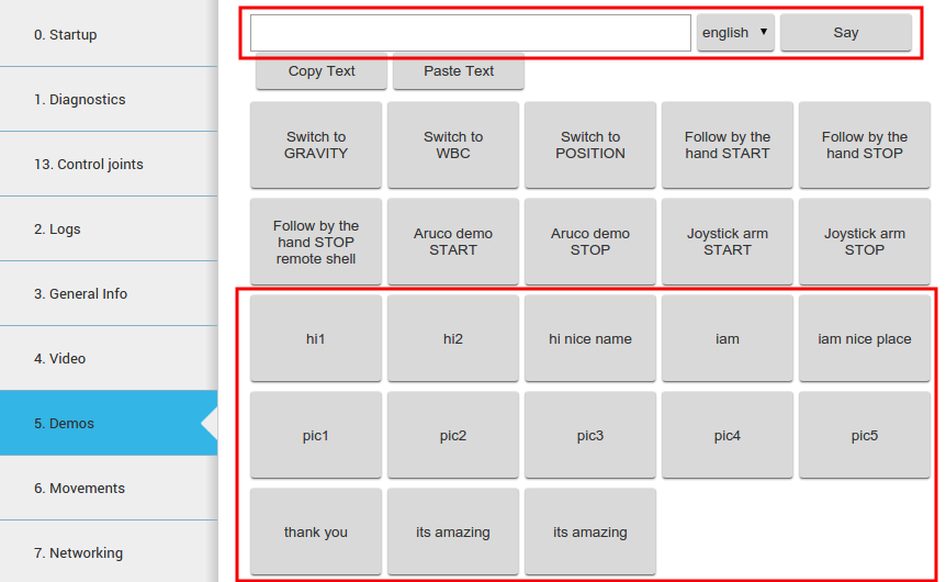
Figure: Voice synthesis in a commands tab of the WebCommander
23.3.2 Command line
Goals to the action server can be sent through command line by typing:
rostopic pub /tts/goal pal_interaction_msgs/TtsActionGoal
Then, by pressing Tab the required message type will be auto-completed. The fields under rawtext can be
edited to synthesize the desired sentence, as in the following example:
rostopic  pub /tts/goal pal_interaction_msgs/TtsActionGoal "header:
    seq: 0
    stamp:
            secs: 0
      nsecs: 0
  frame_id: ''
goal_id:
  stamp:
         secs: 0
         nsecs: 0
  id: ''
goal:
  text:
  rawtext:
         text: 'Hello world'
         lang_id: 'en_GB'
  speakerName: ''
  wait_before_speaking: 0.0"
23.3.3 Action client
A GUI included in the actionlib package of ROS Melodic or actionlib_tools in ROS Noetic can be used to send goals to the voice synthesis server.
In order to be able to execute the action successfully, the ROS_IP environment variable should be exported with the IP direction of your development computer:
export ROS_IP=DEV_PC_IP
The GUI shown in Figure: Voice synthesis using the GUI from actionlib below can be run as follows:
export ROS_MASTER_URI=http://tiago-0c:11311
# For ROS Melodic
rosrun actionlib axclient.py /tts

# For ROS Noetic
rosrun actionlib_tools axclient.py /tts
Editing the fields inside rawtext parameter and pressing the SEND GOAL button will trigger the action.
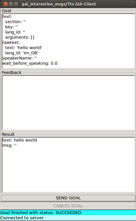
Figure: Voice synthesis using the GUI from actionlib
24 Base motions
24.1 Overview
This section explains the different ways to move the base of TIAGo++. The mobile base is based on a differential drive, which means that a linear and an angular velocity can be set, as shown in Figure: Rotational joints of the head on the 26 Head motions section. First, the motion triggers implemented in the joystick will be exposed, then the underlying ROS API to access the base controller will be presented.
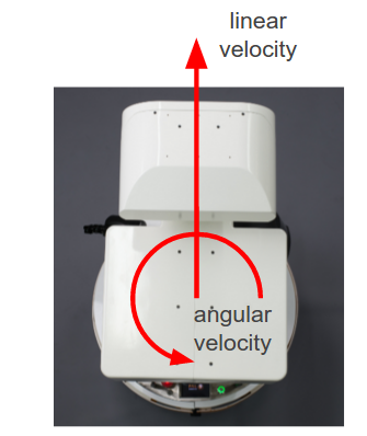
Figure: Mobile base velocities that can be commanded
24.2 Base motion joystick triggers
In order to start moving the base with the joystick, the priority has to be given to this peripheral. In order to gain priority with the joystick, just press the button shown in figue below. Release the priority by pressing the same button.
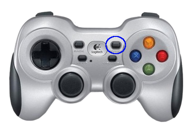
Figure: Taking priority with the joystick
24.2.1 Forward/backward motion
To move the base forward, use the left analog stick.
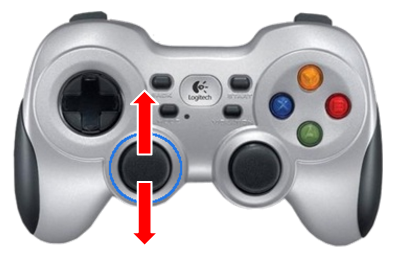
Figure: Base linear motion with the joystick
24.2.2 Rotational motion
In order to make the base rotate on its Z axis, the right analog stick has to be operated, as shown in figure below:
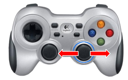
Figure: Base rotational motion with the joystick
24.2.3 Changing the speed of the base
The default linear and rotation speed of the base can be changed with the following button combinations:
To increase linear speed, see figure a
To decrease linear speed, see figure b
To increase angular speed, see figure c
To decrease angular speed, see figure d
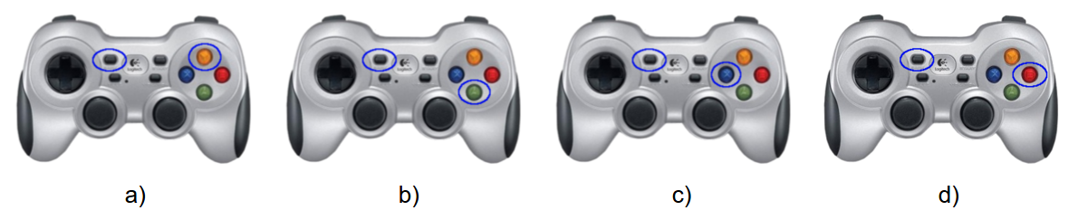
Figure: Joystick button combinations to change speed
24.3 Mobile base control ROS API
At user level, linear and rotational speeds can be sent to the mobile base controller using the following topic:
/mobile_base_controller/cmd_vel (geometry_msgs/Twist)
The given linear and angular velocities are internally translated to the required angular velocities of each of the two drive wheels.
24.4 Mobile base control diagram
Different ROS nodes publish velocity commands to the mobile base
controller through the /mobile_base_controller/cmd_vel topic. In
Figure: Mobile base control diagram (figue below), the default nodes
trying to gain control of the mobile base are shown. From one side,
there are velocities triggered from the joystick and from the other
side, there are commands from the move_base node, which is used by
the navigation pipeline that is presented in
section Navigation.
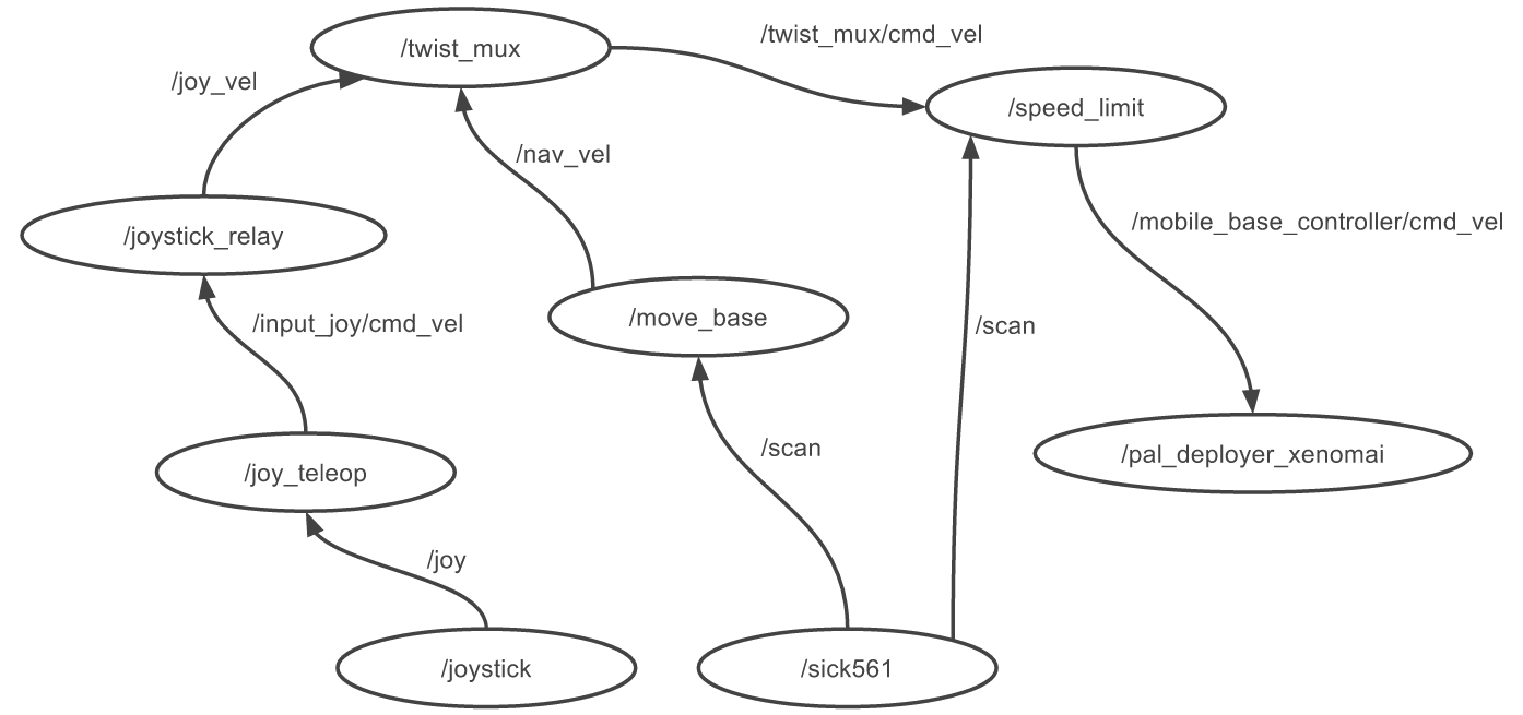
Figure: Mobile base control diagram
25 Torso motions
25.1 Overview
This section explains how to move the primsatic joint of the lifting torso of TIAGo++ either by using the joystick or the available ROS APIs.
25.2 Torso motion joystick triggers
In order to start moving the torso with the joystick, the priority has to be given to this peripheral, as explained in section 24.2 Base motion joystick triggers. Move the torso by using the LB and LT buttons of the joystick, see Figure: Buttons to move the torso. Press LB to raise the torso and LT to move it downwards, see Figure: Torso vertical motions triggered with the joystick.
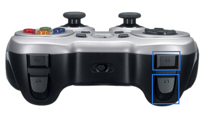
Figure: Buttons to move the torso
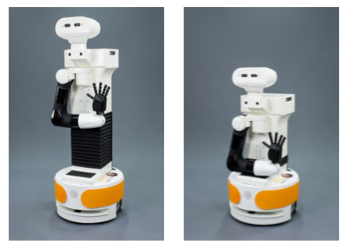
Figure: Torso vertical motions triggered with the joystick
25.3 Torso control ROS API
25.3.1 Topic interfaces
/torso_controller/command (trajectory_msgs/JointTrajectory)
Sequence of positions that the torso joint needs to reach in given time intervals.
/torso_controller/safe_command (trajectory_msgs/JointTrajectory)
Idem as before but the motion is only executed if it does not lead to a self-collision.
25.3.2 Action interfaces
/torso_controller/follow_joint_trajectory (control_msgs/FollowJointTrajectory Action)
This action encapsulates the trajectory_msgs/JointTrajectory message.
/safe_torso_controller/follow_joint_trajectory (control_msgs/FollowJointTrajectory Action)
Idem as before but the goal is discarded if a self-collision will occur.
26 Head motions
26.1 Overview
This section explains how to move the two rotational joints of the head with the joystick and explains the underlying ROS API.
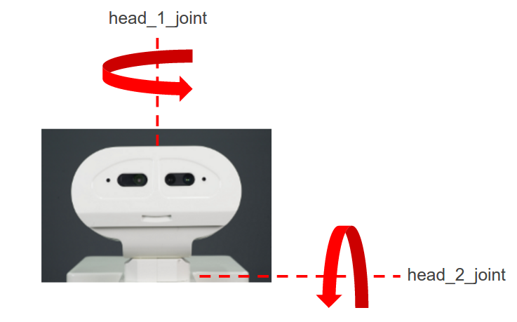
Figure: Rotational joints of the head
26.2 Head motion joystick triggers
The head is moved by using the X, Y, A and B buttons on the right hand side of the joystick, see figure below:
Figure: Buttons to move the head
26.3 Head motions with rqt GUI
The joints of the head can be moved individually using a GUI implemented on the rqt framework that can be launched from a terminal.
In case of running this example with the real robot, i.e. not in simulation, open the terminal in a development computer and first run:
export ROS_MASTER_URI=http://tiago-0c:11311
export ROS_IP=10.68.0.128
Make sure to use your robot’s serial number when exporting the ROS_MASTER_URI variable and to set your development computer’s IP when exporting ROS_IP as explained in section 12.4 ROS communication with the robot.
The GUI is launched in the same terminal as follows:
rosrun rqt_joint_trajectory_controller rqt_joint_trajectory_controller
The GUI is shown in Figure: rqt GUI to move individual joints of the head. Note that other groups of joints, i.e. head, torso, hand and gripper, can also be
moved using this GUI. Furthermore, this is equivalent to using the control foints tab in the WebCommander,
as explained in section 13.4.5 JointCommander Plugin Configuration. In order to move the head joints, select /controller_manager in the combo
box on the left and the head_controller on the right. Sliders for the two actuated joints of the head will show up.
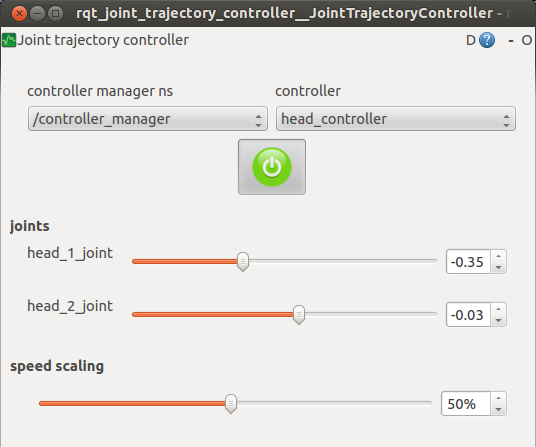
Figure: rqt GUI to move individual joints of the head
26.4 Head control ROS API
26.4.1 Topic interfaces
/head_controller/command (trajectory_msgs/JointTrajectory)
Sequence of joint positions that needs to be achieved in given time intervals.
26.4.2 Action interfaces
/head_controller/follow_joint_trajectory (control_msgs/FollowJointTrajectory)
This action encapsulates the trajectory_msgs/JointTrajectory message.
/head_controller/point_head_action (control_msgs/PointHead Action)
This action is used to make the robot look to a given cartesian space.
27 Arm motions
27.1 Overview
This section explains how to move the 7 DoF of TIAGo++’s arms using a GUI or the available ROS APIs.
27.2 Arm motions with rqt GUI
The joints of the arms can be moved individually using a GUI implemented on the rqt framework.
In case of running this example with the real robot, i.e. not in simulation, open the terminal in a development computer and first run:
export ROS_MASTER_URI=http://tiago-0c:11311
export ROS_IP=10.68.0.128
Make sure to use your robot’s serial number when exporting the ROS_MASTER_URI variable and to set your development computer’s IP when exporting ROS_IP as explained in section 12.4 ROS communication with the robot.
The GUI is launched as follows:
rosrun rqt_joint_trajectory_controller rqt_joint_trajectory_controller
The GUI is shown in Figure: rqt GUI to move individual joints below. Note that other groups of joints, i.e. head, torso, hand, gripper, can be also
moved using this GUI. This is equivalent to using the control joints tab in the WebCommander, as explained in
section 13.4.5 JointCommander Plugin Configuration. In order to move the arm joints, select /controller_manager in the combo box at the left
and either arm_left_controller or arm_right_controller at the right. Sliders for the seven joints of the selected arm will show up.
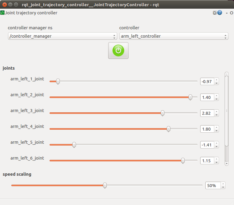
Figure: rqt GUI to move individual joints
27.3 Arm control ROS API
27.3.1 Topic interfaces
/arm_left_controller/command (trajectory_msgs/JointTrajectory)
Sequence of positions that the left arm joints have to reach in given time intervals.
/arm_left_controller/safe_command (trajectory_msgs/JointTrajectory)
Idem as before but the motion is only executed if it does not lead to a self-collision.
/arm_right_controller/command (trajectory_msgs/JointTrajectory)
Sequence of positions that the right arm joints have to reach in given time intervals.
/arm_right_controller/safe_command (trajectory_msgs/JointTrajectory)
Idem as before but the motion is only executed if it does not lead to a self-collision.
27.3.2 Action interfaces
/arm_left_controller/follow_joint_trajectory (control_msgs/FollowJointTrajectory Action)
This action encapsulates the trajectory_msgs/JointTrajectory message.
/safe_arm_left_controller/follow_joint_trajectory (control_msgs/FollowJointTrajectory Action)
Idem as before but the goal is discarded if a self-collision will occur.
/arm_right_controller/follow_joint_trajectory (control_msgs/FollowJointTrajectory Action)
This action encapsulates the trajectory_msgs/JointTrajectory message.
/safe_arm_right_controller/follow_joint_trajectory (control_msgs/FollowJointTrajectory Action)
Idem as before but the goal is discarded if a self-collision will occur.
28 Hand motions
28.1 Overview
This section explains how to move the three motors of the Hey5 hand using the joystick or the rqt GUI, and explains the ROS API of the hand.
28.2 Hand motion joystick triggers
There are joystick triggers to close and open the right hand of TIAGo++ using buttons RT and BT, respectively, as shown in figure below:
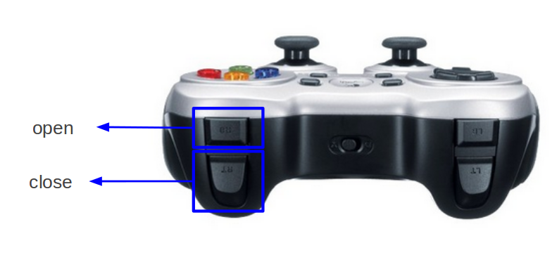
Figure: Joystick buttons to trigger hand close/open motions
No joystick triggers are provided for the left end-effector of TIAGo++. Nevertheless the user can change the configuration of the joystick triggers editing the corresponding yaml file.
28.3 Hand motions with rqt GUI
The joints of the hand can be moved individually using a GUI implemented on the rqt framework.
In case of running this example with the real robot, i.e. not in simulation, open the terminal in a development computer and first run:
export ROS_MASTER_URI=http://tiago-0c:11311
export ROS_IP=10.68.0.128
Make sure to use your robot’s serial number when exporting the ROS_MASTER_URI variable and to set your
development computer’s IP when exporting ROS_IP as explained in section 12.4 ROS communication with the robot.
The GUI is launched as follows:
rosrun rqt_joint_trajectory_controller rqt_joint_trajectory_controller
The GUI is shown in figure below. Note that other groups of joints, i.e. head, torso, hand and gripper can also be
moved using this GUI. This is equivalent to using the control joints tab in the WebCommander, as explained
in section 13.4.5 JointCommander Plugin Configuration. In order to move the hand joints, select /controller_manager in the combo box on the
left and either hand_left_controller or hand_right_controller on the right. Sliders for the three actuated joints of the hand will show up.
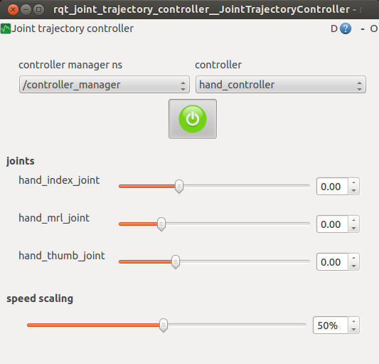
Figure: rqt GUI to move individual joints of the hand
28.4 Hand control ROS API
28.4.1 Topic interfaces
/hand_left_controller/command (trajectory_msgs/JointTrajectory)
Sequence of positions that the left hand joints have to reach in given time intervals.
/hand_left_current_limit_controller/command (pal_control_msgs/ActuatorCurrentLimit)
Set maximum allowed current for each actuator of the left hand specified as a factor in [0,1] of the actuator’s maximum current.
/hand_right_controller/command (trajectory_msgs/JointTrajectory)
Sequence of positions that the right hand joints have to reach in given time intervals.
/hand_right_current_limit_controller/command (pal_control_msgs/ActuatorCurrentLimit)
Set maximum allowed current for each actuator of the right hand specified as a factor in [0, 1] of the actuator’s maximum current.
28.4.2 Action interfaces
/hand_left_controller/follow_joint_trajectory (control_msgs/FollowJointTrajectory Action)
This action encapsulates the trajectory_msgs/JointTrajectory message for the left hand.
/hand_right_controller/follow_joint_trajectory (control_msgs/FollowJointTrajectory Action)
This action encapsulates the trajectory_msgs/JointTrajectory message for the right hand.
29 PAL gripper motions
29.1 Overview
This section explains how to command the PAL gripper of TIAGo++ using a GUI or the available ROS APIs.
29.2 Gripper motion joystick triggers
There are joystick triggers order to close and open the right gripper of TIAGo++ using buttons RT and BT, respectively, as shown in figure below:
Figure: Joystick buttons to trigger hand close/open motions
No joystick triggers are provided for the left end-effector of TIAGo++. Nevertheless the user can change the configuration of the joystick triggers editing the corresponding yaml file.
29.3 Gripper motions with rqt GUI
In case of running this example with the real robot, i.e. not in simulation, open the terminal in a development computer and first run:
export ROS_MASTER_URI=http://tiago-0c:11311
export ROS_IP=10.68.0.128
Make sure to use your robot’s serial number when exporting the ROS_MASTER_URI variable and to set your development computer’s IP when exporting ROS_IP as explained in section 12.4 ROS communication with the robot.
Launch the rqt GUI to command groups of joints as follows:
rosrun rqt_joint_trajectory_controller rqt_joint_trajectory_controller
Select the controller manager namespace available. Select either gripper_left_controller or
gripper_right_controller and then two sliders, one for each gripper joint. One slide controls the position of each finger.
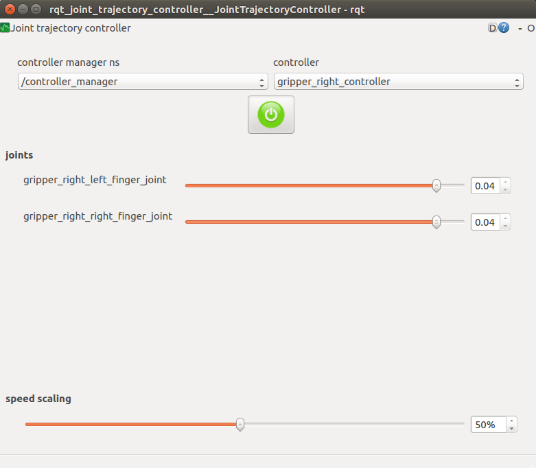
Figure: rqt GUI to move the gripper
29.4 Gripper control ROS API
29.4.1 Topic interfaces
/parallel_gripper_left_controller/command (trajectory_msgs/JointTrajectory)
/parallel_gripper_right_controller/command (trajectory_msgs/JointTrajectory)
These topics are used to specify the desired distance between the robot’s fingers. A single target position or a sequence of positions can be specified. For instance, the following command moves the gripper motors so that the distance between the fingers becomes 3 cm:
rostopic pub /parallel_gripper_left_controller/command trajectory_msgs/JointTrajectory "
header:
    seq: 0
    stamp:
        secs: 0
        nsecs: 0
    frame_id: ''
joint_names:
- 'parallel_gripper_joint'
points:
- positions: [0.03]
    velocities: []
    accelerations: []
    effort: []
    time_from_start:
        secs: 1
        nsecs: 0" --once
/gripper_left_controller/command (trajectory_msgs/JointTrajectory)
/gripper_right_controller/command (trajectory_msgs/JointTrajectory)
Sequence of positions to send to each motor of the gripper. Position 0 corresponds to a closed gripper and 0.04 corresponds to an open gripper. An example to set the fingers to different positions using command line is shown below:
rostopic pub /gripper_left_controller/command trajectory_msgs/JointTrajectory "
header:
    seq: 0
    stamp:
        secs: 0
        nsecs: 0
    frame_id: ''
joint_names: ['gripper_left_left_finger_joint', 'gripper_left_right_finger_joint']
points:
- positions: [0.04, 0.01]
    velocities: []
    accelerations: []
    effort: []
    time_from_start:
        secs: 1
        nsecs: 0" --once
29.4.2 Action interfaces
/parallel_gripper_left_controller/follow_joint_trajectory (control_msgs/FollowJointTrajectory Action)
/parallel_gripper_right_controller/follow_joint_trajectory (control_msgs/FollowJointTrajectory Action)
These actions encapsulate the trajectory_msgs/JointTrajectory message in order to perfom gripper motions with information about when it ends or whether it has executed succesfully.
29.4.3 Service interfaces
/parallel_gripper_left_controller/grasp (std_msgs/Empty)
/parallel_gripper_right_controller/grasp (std_msgs/Empty)
These services make the grippers close the fingers until a grasp is detected. When that happens the controller keeps the fingers in the position in order to hold the object, while not overheating the motors.
An example on how to call thid service from the command line is:
rosservice call /parallel_gripper_left_controller/grasp
30 Robotiq 2F-85/140 gripper
30.1 Overview
This section explains how to command the Robotiq 2F-85/140 gripper of TIAGo++ using a GUI or the available ROS APIs.
30.2 Gripper motion joystick triggers
There are joystick triggers order to close and open the right gripper of TIAGo++ using buttons RT and BT, respectively, as shown in figure below:
Figure: Joystick buttons to close/open the gripper
No joystick triggers are provided for the left end-effector of TIAGo++. Nevertheless the user can change the configuration of the joystick triggers editing the corresponding yaml file.
30.3 Gripper motions with rqt GUI
In case of running this example with the real robot, i.e. not in simulation, open the terminal in a development computer and first run:
export ROS_MASTER_URI=http://tiago-0c:11311
export ROS_IP=10.68.0.128
Make sure to use your robot’s serial number when exporting the ROS_MASTER_URI variable and to set your
development computer’s IP when exporting ROS_IP as explained in Section 12.4 ROS communication with the robot
Launch the rqt GUI to command groups of joints as follows:
rosrun rqt_joint_trajectory_controller rqt_joint_trajectory_controller
Select the controller manager namespace available. Select either gripper_left_controller or
gripper_right_controller and then one slider will appear, as shown in figure below:
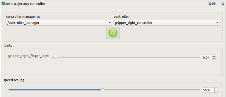
Figure: rqt GUI to move the gripper
30.4 Gripper control ROS API
30.4.1 Topic interfaces
/gripper_left_controller/command (trajectory_msgs/JointTrajectory)
/gripper_right_controller/command (trajectory_msgs/JointTrajectory)
Sequence of positions to send to each motor of the gripper. Position 0 corresponds to a closed gripper and 0.04 corresponds to an open gripper. An example to set the fingers to different positions using command line is shown below:
rostopic pub /gripper_left_controller/command trajectory_msgs/JointTrajectory "
header:
    seq: 0
    stamp:
        secs: 0
        nsecs: 0
    frame_id: ''
joint_names: ['gripper_left_finger_joint']
points:
- positions: [0.04]
    velocities: []
    accelerations: []
    effort: []
    time_from_start:
        secs: 1
        nsecs: 0" --once
/gripper_motor/gripper_status (std_msgs/UInt8)
Provide the real time status of the gripper:
rostopic echo -n1 /gripper_motor/gripper_status "
data: 249
---
Find in the table below the status code:
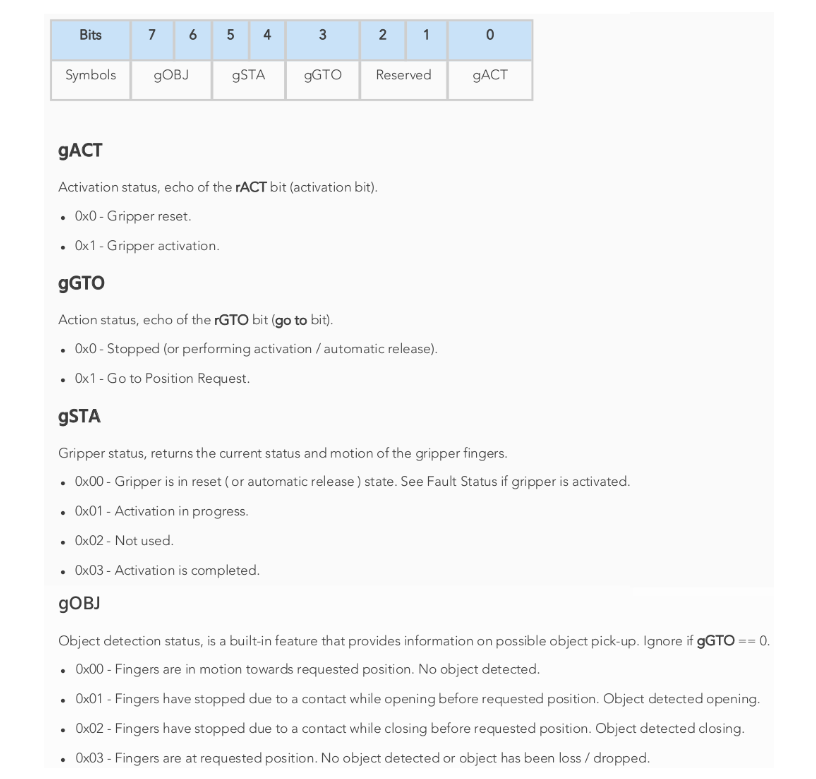
Figure: Robotiq 2F-85/140 gripper status code
First, we convert from base 10 to base 2:
249 -> 11111001
gOBJ corresponds the first two digits 11 that converted to hex is 0x03
Going go the table 0x03 corresponds to: “Fingers are at requested position. No object detected or object has been loss / dropped”
Applying the same logic to all digits we get the corresponding gripper status:
“Fingers are at requested position. No object detected or object has been loss / dropped.”
“Activation is complete”
“Go to Position Request”
“Gripper Activation”
Note
In some circumstances the object detection feature may not detect an object even if it is successfully grasped. For instance, picking up a thin object may be successful without the object detection status being triggered. In such applications, the “Fingers are at requested position” status of register gOBJ, is sufficient to proceed to the next step of the routine.
/gripper_motor/grip_force (std_msgs/Float64)
In order to modify the speed and applied force during gripping, two input topics have been enabled. The value must be between 0 and 1, with 1 being the maximum speed or force.
Find below an example setting both values to 0.5:
rostopic pub /gripper_motor/grip_speed std_msgs/Float64 "data: 0.5"
rostopic pub /gripper_motor/grip_force std_msgs/Float64 "data: 0.5"
30.4.2 Action interfaces
/gripper_left_controller/follow_joint_trajectory (control_msgs/FollowJointTrajectory Action)
/gripper_right_controller/follow_joint_trajectory (control_msgs/FollowJointTrajectory Action)
These actions encapsulate the trajectory_msgs/JointTrajectory message in order to perfom
gripper motions with information about when it ends or whether it has executed succesfully.
30.4.3 Service interfaces
/gripper_left_controller/grasp (std_msgs/Empty)
/gripper_right_controller/grasp (std_msgs/Empty)
These services make the grippers close the fingers until a grasp is detected. When that happens the controller keeps the fingers in the position in order to hold the object, while not overheating the motors.
An example on how to call thid service from the command line is:
rosservice call /parallel_gripper_left_controller/grasp
31 Robotiq EPick vacuum gripper
31.1 Overview
This section explains how to command the Robotiq EPick vacuum gripper of TIAGo++ using a GUI or the available ROS APIs.
31.2 Gripper motion joystick triggers
The gripper can be controlled with the handheld controller shown below in the figure below. The joystick triggers are used in order to active or deactivate the right gripper using the buttons RT and RB, respectively.
Note
No joystick triggers are provided for the left end-effector of TIAGo++. Nevertheless the user can change the configuration of the joystick triggers editing the corresponding yaml file.
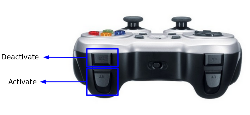
Figure: Joystick buttons to close/open the gripper
31.3 Gripper control ROS API
31.3.1 Topic interfaces
/gripper_left_vacuum/command (trajectory_msgs/JointTrajectory)
/gripper_right_vacuum/command (trajectory_msgs/JointTrajectory)
The message that can be send to the gripper is shown in the code snippet below. Sending a command with a value other than zero will activate the vacuum gripper. Deactivating the gripper is done by sending the command with a value of 0.0.
Note
Take note of the status of the gripper when sending these topics. When the object is manually removed from the gripper this will not automatically deactivate the gripper. In order to use it again, first send a command to deactivate before the gripper can be activated again. If the gripper is activated without deactivating first, the gripper will fail to work.
rostopic pub /gripper_left_vacuum/command std_msgs/Float64
    "data: 0.0"
Real time status
/gripper_left_vacuum/gripper_status (std_msgs/UInt8MultiArray)
/gripper_right_vacuum/gripper_status (std_msgs/UInt8MultiArray)
Provide the real time status of the gripper:
rostopic echo -n1 /gripper_left_vacuum/gripper_status

layout:
  dim: []
  data_offset: 0
data: [249, 0]
---
In the table below the status code can be found:
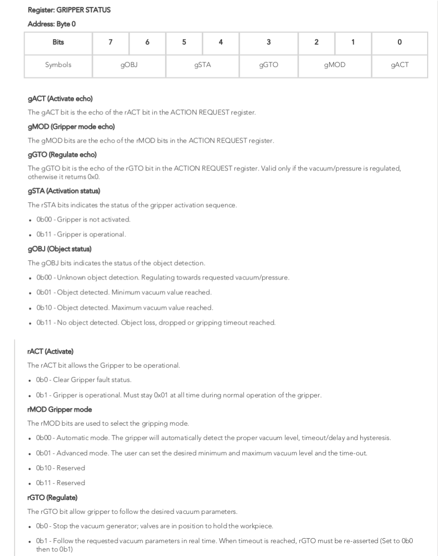
Figure: Robotiq EPick vacuum gripper status code
The first step is to convert the status number to it’s binary form:
249 -> 11111001
gOBJ corresponds the first two digits 11, and is denoted by the status 0b11. Using the table, 0b11 corresponds to: “No object detected. Object loss, dropped or gripping timeout reached.”
Applying the same logic to all digits we get the corresponding gripper status:
gOBJ: “Fingers are at requested position. No object detected or object has been loss / dropped.”
gSTA: “Gripper is operational.”
gGTO: “Follow the requested parameters in real time.”
gMOD: “Automatic mode.”
gACT: “Gripper is operational.”
Warning
If the status output of gOBJ shows “Object detected. Minimum value reached” often while making a continuous noise, it is possible the suction cup of the gripper is not attached properly. This way air will get through and the gripper cannot achieve vacuum. To resolve this ensure the suction cup is tightened properly. The figure below shows the connection of the suction cup to the end-effector. Another cause of this problem is if the surface of the object is rough or a bit porous, increasing the difficulty of reaching vacuum.
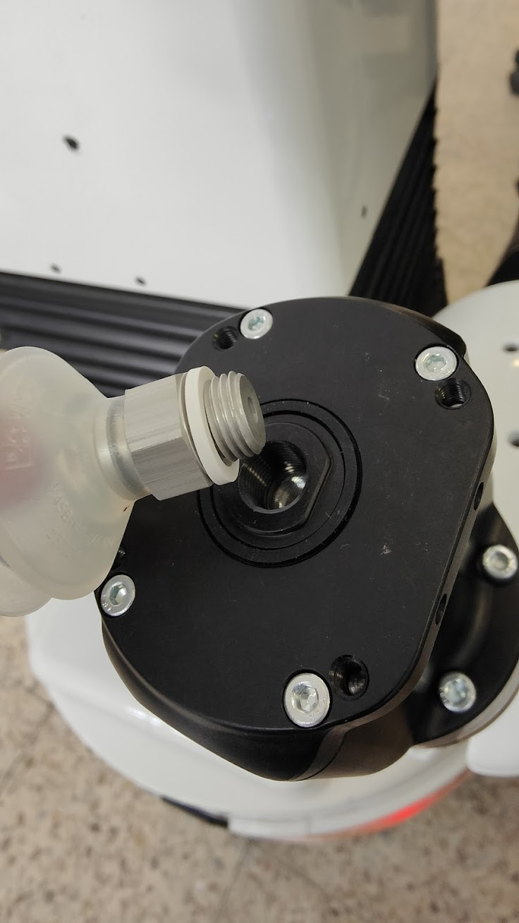
Figure: Before use ensure the suction cup has been thightly screwed in the end-effector.
Real time status message
/gripper_left_vacuum/gripper_status_human (std_msgs/String)
/gripper_right_vacuum/gripper_status_human (std_msgs/String)
These topics automaticall translate the status of the grippers to the different messages per byte given by the table above.
rostopic echo -n1 /gripper__left_vacuum/gripper_status_human

data: "Gripper status: Gripper is operational Follow the requested vacuum parameters in\
  \ real time Gripper is operational No object detected. Object loss, dropped or gripping\
  \ timeout reached"
---
Real time grasp status
/gripper_left_vaccuum/is_grasped (std_msgs/Bool)
/gripper__right_vaccuum/is_grasped (std_msgs/Bool)
These topics convert the gripper status to a boolean if the gripper indeed has grasped an object.
rostopic echo -n1 /gripper_left_vacuum/is_grasped

data: True
---
31.3.2 Service interfaces
/gripper_left_controller/grasp (std_msgs/Empty)
/gripper_right_controller/grasp (std_msgs/Empty)
These services the grippers for three seconds until it has grasped an object. When the gripper has not grasped an object within three seconds, it will deactivate. If the gripper has grasped an object it is possible to manually remove the object from the gripper . In this case the gripper will be deactivated automatically and a new grasping command can be send immediately.
An example on how to call this service from the command line is shown below:
rosservice call /gripper_left_controller/grasp "{}"
32 End-effector exchange
32.1 Overview
This section explains how to exchange the TIAGo++ end-effectors.
32.2 Changing the end-effector software configuration
In order to change the configuration of the robot, go to the robot’s web commander and to the Settings tab. Select the end effector from the drop-down menu (Please refer to the section 13.3.11 Settings Tab for further details) that you are going to install and reboot the robot before proceeding with the following steps.
32.3 Mounting an end-effector
The procedure to exchange the end-effector is shown in the following video Demounting and mounting TIAGo’s end-effectors. An overview of the steps is given below.
32.3.1 Unmounting the previous end-effector
Firstly, make sure that the emergency button is pressed and the robot is completely turned off in order to ensure maximum safety during the procedure.
Locate the fastener that locks the end-effector in the end-effector clamp, as shown in the figure below:
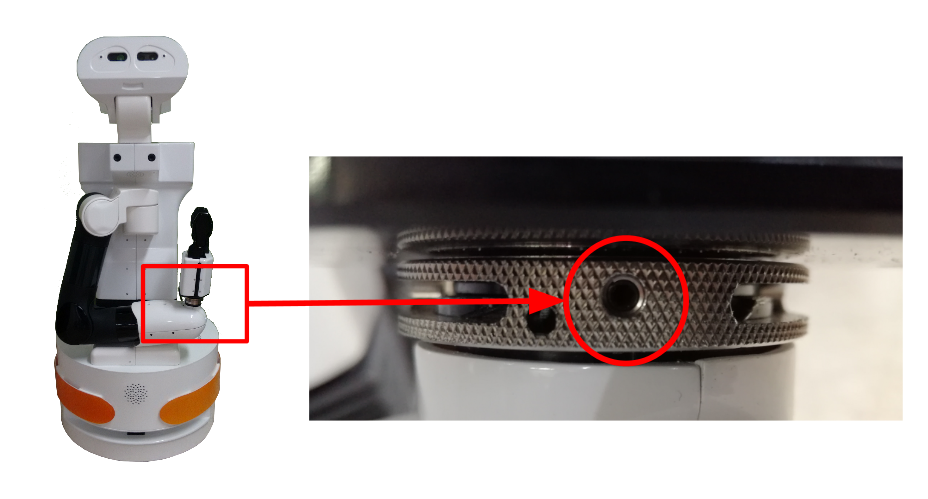
Figure: Srew locking the clamp of the end-effector
Use an appropriate Allen key to loosen the locking screw of the clamp, as shown in the figure below.
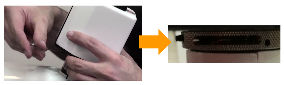
Figure: Loosen the locking-screw
Unlock the clamp by rotating it counterclockwise as shown in the figure below.
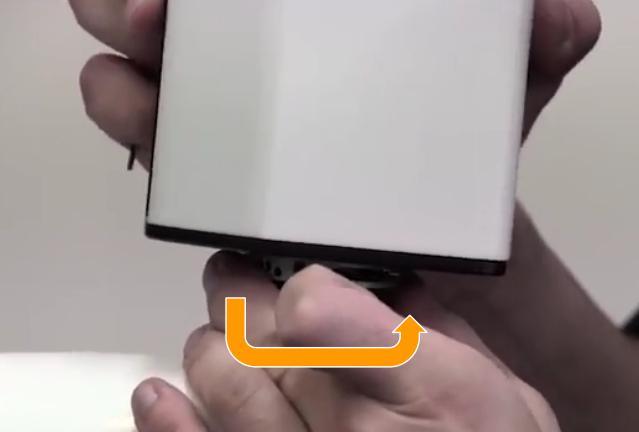
Figure: Unlocking the clamp by hand
If the clamp cannot be unlocked by hand, use the tool provided with the spare end-effector, see the figure below. Insert the tool in the groove edge of the clamp and rotate it counterclockwise in order to unlock it, as shown in the figure below.
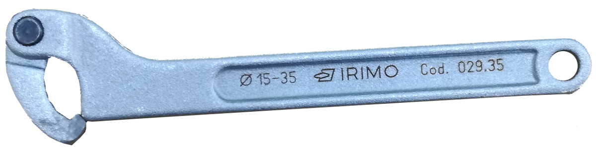
Figure: Tool for end-effector clamp
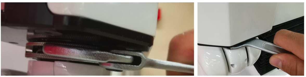
Figure: Unlocking the clamp using the tool provided
Once the clamp is unlocked, unmount the end-effector by lightly shaking and pulling it at the same time, see the figure below.
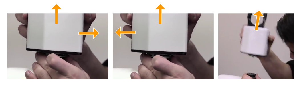
Figure: Unmounting the gripper
32.3.2 Mounting an end-effector
Align the end-effector and the clamp, as shown in the figure below.

Figure: Correct alignment of the clamp
Position the end-effector on top of the wrist mounting plate so the plate pin fits in the corresponding hole of the end-effector plate, see the figure below.
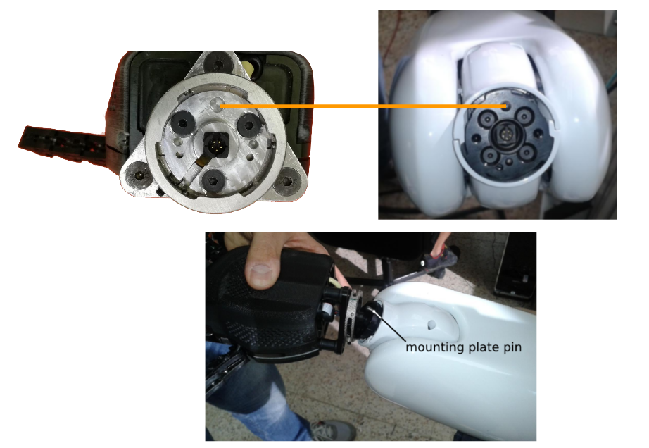
Figure: Alignment of the end-effector with the wrist mounting plate
Insert the end-effector by pressing until the mounting plate of the wrist is in contact with the end-effector plate, as shown in the figure below.
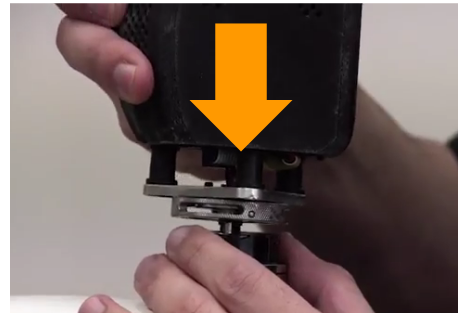
Figure: Insertion of the end-effector
Use the tool to twist the clamp clockwise in order to tighten it, as shown in the figure below.
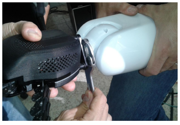
Figure: Tightening Hey5 clamp
Now tighten the locking screw, as shown in the figure below.
Figure: Tightening Hey5 clamp
32.3.3 Validation
In order to validate that the new end-effector has been correctly assembled and its software properly activated, press the electric key switch , release the emergency button and hold the On button of the mobile base for two seconds.
When the robot has correctly started up, go to the Diagnostics tab of the WebCommander, and under the Motors sections check that of the end-effector are shown in green.
32.4 Mounting the parallel gripper
The procedure to exchange the Hey5 hand with the parallel gripper is the same.
33 Force-Torque sensor calibration
33.1 Overview
This section explains how to use the Force-Torque (F/T) calibration procedure for the F/T sensor on the wrist. When reading the values of the F/T sensor there is typically a certain ammount of noise, some caused by the sensor itself and the environment conditions like pressure, etc., some caused by the fact that the end-effector exerts a force on the sensor due to its weight.
The weight of the end-effector can easilly be computed, and its effect compensated without much difficulty, but, in order to calibrate the offsets of the sensor, an experimental method must be used. This package provides an experimental method to compute said offsets in a simple, convenient way.
It is important to note that the offsets of the F/T sensor may slightly change during the operation of the arm, so it is suggested to perform this procedure every four or five hours of continued use.
The computed offsets are stored in the ROS param server and they are used by the dynamic calibration together with the weight of the end-effector to compensate these elements respect the current position of the wrist and the F/T sensor.
33.2 Running the calibration
Warning
The calibration procedure will extend the arm in the forward direction to its maximum length. For this reason it is important that the robot is, at least, more than one meter away from any obstacles. It is also important not to touch the end effector during the procedure, as this would result in incorrect offsets.
The calibration is controlled by an Action interface, which will perform a series of motions with the arm, compute the offsets of the F/T sensor, and set them up. Once the procedure is completed, if successful, stop and start the nodes that do the dynamic calibration:
pal-stop ft_calibration
pal-start ft_calibration
pal-stop ft_left_calibration
pal-start ft_left_calibration
The corrected readings, compensating both offset and end-effector weight, will be published in /wrist_left_ft/corrected and wrist_right_ft/corrected.
33.2.1 Action Interface
/wrist_left_ft/calibrate (pal_ft_automatic_calibration_msgs/CalibrateFTOffsets Action)
/wrist_right_ft/calibrate (pal_ft_automatic_calibration_msgs/CalibrateFTOffsets Action)
The goal, feedback and result messages of these actions are empty messages.
The calibration can also be triggered from terminal by running:
$ rostopic pub /wrist_left_ft/calibrate/goal
  pal_ft_automatic_calibration_msgs/CalibrateFTOffsetsActionGoal "header:
    seq: 0
    stamp:
        secs: 0
        nsecs: 0
    frame_id: ''
  goal_id:
    stamp:
        secs: 0
        nsecs: 0
    id: ''
  goal: {}"
33.3 Parameter customization
There are several parameters that can be changed to modify the procedure. Correct values are provided for the Hey5 hand, the PAL parallel gripper and the Schunk parallel gripper, they would only need to be updated in case of integrating a different end-effector.
end_effector_weight_kg: Weight of the end-effector in Kg.CoM_respect_ft_frame/offx: X component of the position of the center of mass of the end-effector, expressed in meters with respect to the F/T sensor frame.CoM_respect_ft_frame/offy: Y component of the position of the center of mass of the end-effector, expressed in meters with respect to the F/T sensor frame.CoM_respect_ft_frame/offz: Z component of the position of the center of mass of the end-effector, expressed in meters with respect to the F/T sensor frame.
These parameters can be found in:
pal_ft_automatic_calibration_tiago/config/end_effector_params.yaml where end-effector can be pal-gripper, pal-hey5 or schunk-wsg.
34 Upper body motions engine
TIAGo++ is provided with a motions engine to play back predefined motions involving joints of the upper body.
A default library with several motions is provided, and the user can add new motions that can be played at
any time. The motions engine provided with TIAGo++ is based on the play_motion ROS package, which is
available in http://wiki.ros.org/play_motion.
This package contains a ROS Action Server that acts as a demultiplexer to send goals to different action servers in charge of commanding different groups of joints. The figure below shows the role of play_motion in order to play back predefined upper body motions.
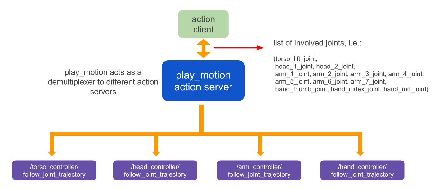
Figure: play_motion action server role
The different groups of actuated joints defined in TIAGo++ are those shown in table:
Group of joints |
Joints included |
Torso |
torso_lift |
Head |
head_1, head_2 |
Arm left |
arm_left_1, arm_left_2, arm_left_3, arm_left_4, arm_left_5, arm_left_6, arm_left_7 |
Arm right |
arm_right_1, arm_right_2, arm_right_3, arm_right_4, arm_right_5, arm_right_6, arm_right_7 |
Hand left |
hand_left_thumb, hand_left_index, hand_left_mrl |
Hand right |
hand_right_thumb, hand_right_index, hand_right_mrl |
Gripper left |
gripper_left_left_finger, gripper_right_right_finger |
Gripper right |
gripper_right_left_finger, gripper_right_right_finger |
The motions that play_motion is able to play back are based on a sequence of joint positions that need to be reached within given time intervals.
34.1 Motions library
The motion library is stored in:
tiago_dual_bringup/config/motions/tiago_dual_motions_general.yaml,
which contains motions not moving the end-effector joints, and
tiago_dual_bringup/config/motions/tiago_dual_motions_X-Y.yaml
where X refers to the type of left end-effector and Y to the right end-effector installed.
The contents of these files are uploaded to theROS param server during the boot up of the robot in /play_motion/motions.
When the play_motion action server is launched, it looks for the motions defined in the param server.
The yaml sorting the predefined motions file can be edited as follows:
roscd tiago_dual_bringup
cd config/motions
vi tiago_motions_X-Y.yaml
The motions already defined in the library are:
home
home_left
home_right
horizontal_reach
reach_floor
reach_floor_left
reach_floor_right
reach_max
reach_max_left
reach_max_right
vertical_reach
wave
offer
offer_left
offer_right
open_both
open_left
open_right
close_both
close_left
close_right
New motions can be added to the library by editing the yaml file in the tiago_dual_bringup package.
34.2 Motions specification
Every motion is specified with the following data structure:
joints: list of joints used by the motion. Note that by convention, when defining a motion involving a given joint, the rest of the joints in the subgroup must be also included in the motion specification. For example, if the predefined motion needs to move head_1 joint, then it also needs to include head_2 joint, as they both belong to the same group. See the table of Group of joints.
- points: list of the following tuple:
positions: list of positions that need to be reached by every joint
time_from_start: time given to reach the positions specified above
meta: meta information that can be used by other applications
As example, the specification of the wave motion is shown in figure below:
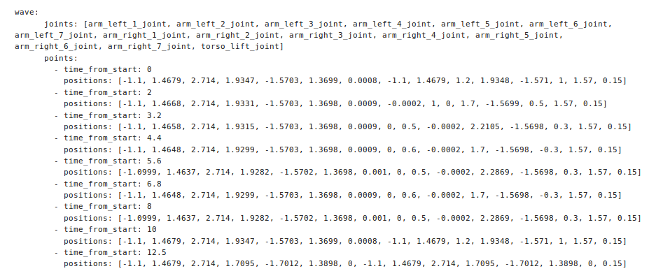
Figure: wave motion definition
As can be seen, the joints included in the motion are those in the arm group.
34.3 Using predefined motions safely
Special care needs to be taken when defining predefined motions, as if they are not well defined self-collisions or collisions with the environment may occur.
A safety feature is included in play_motion in order to minize the risk of self-collisions at the begining of
the motion. As the upper body joints can be in any arbitrary position before starting the motion, the joint
movements that must be made in order to reach the first predefined positions in the points tuple are the
most dangerous. For this reason, play_motion can use motion planning included in MoveIt! in order to find
joint trajectories that will prevent self-collisions when reaching the first desired position of the motion.
The planning stage takes only a matter of seconds. The user can disable this feature, as shown in the next section. Nevertheless, it is strongly recommended not to do so unless the position of the joints before executing the motion are well known, and a straight trajectory of the joints towards the first intermediate position is safe.
34.4 ROS interface
The motion engine exposes an Action Server interface in order to play back predefined upper body motions.
34.4.1 Action interface
/play_motion (play_motion_msgs/PlayMotion Action)
This action plays back a given predefined upper body motion.
The goal message includes the following data:
motion_name: name of the motion as specified in the motions yaml file.
skip_planning: when true, motion planning is not used to move the joints from the initial position to the first position specified in the list of positions. This parameter should be set to
Falseby default tominimize the risk of self-collisions, as explained in the 34.3 Using predefined motions safely subsection.priority: unimplemented feature. For future use.
34.5 Action clients
There are multiple ways to send goals to play_motion Action Server. TIAGo++ provides several action
clients in order to request the execution of predefined upper body motions. These action clients are summarized in figure below:
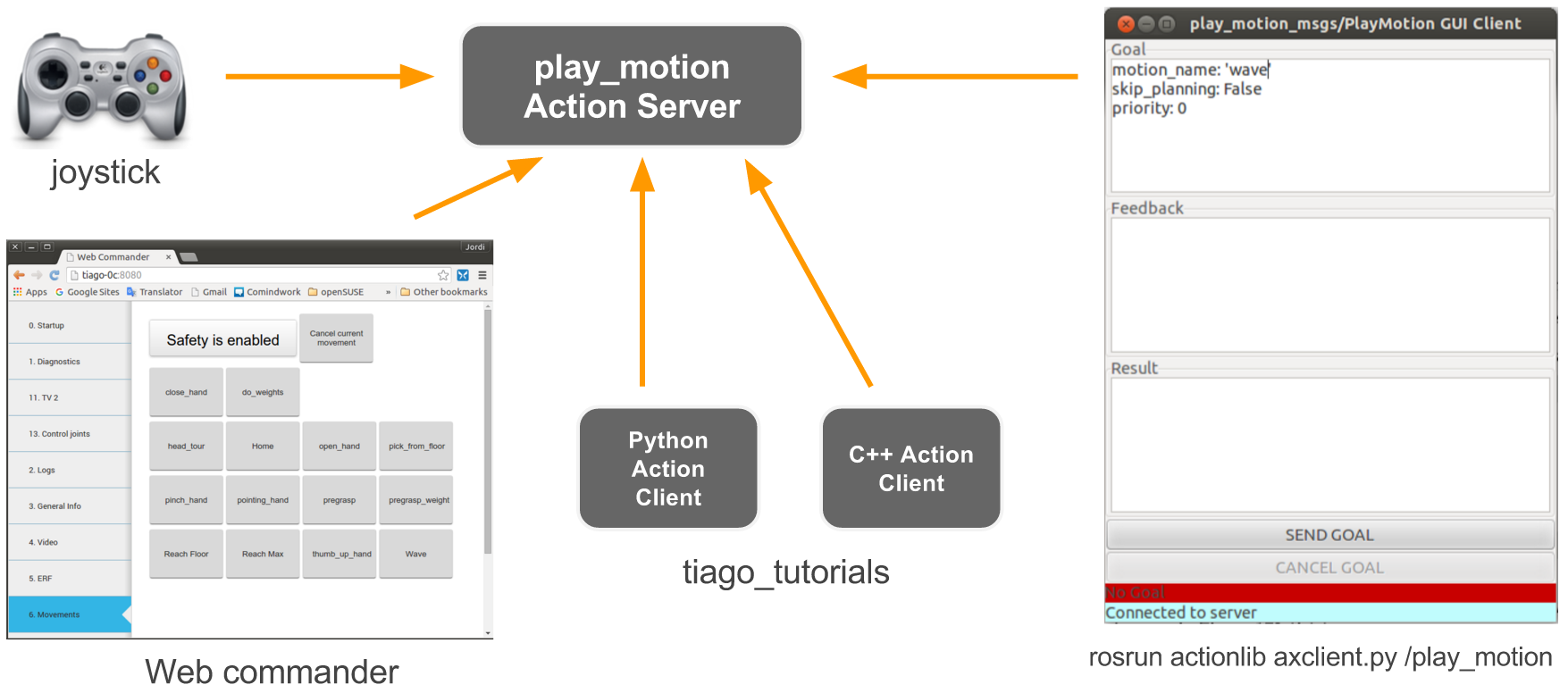
Figure: play_motion action clients provided
Note that predefined motions can be executed from the:
Joystick: several combinations of buttons are already defined to trigger torso and hand/gripper motions.
WebCommander: all the predefined motions including the
metadata intiago_motions.yamlwill appear in theMovementstab of the web interface.Axclient GUI: using this graphical interface, any predefined upper body motion can be executed.
Examples in the tutorials: examples in C++ and in Python are provided in
tiago_tutorials/run_motionpackage on how to send goals to the/play_motionaction server.
35 Navigation
35.1 Overview
This section details TIAGo++’s autonomous navigation framework. The ROS 2D navigation stack is the basis of TIAGo++’s navigation. The navigation software is composed of all the ROS nodes running in the robot that are able to perform SLAM - mapping and localization using the laser on the mobile base - and path planning to bring the robot to any map location, whilst avoiding obstacles and preventing collisions using laser and sonar readings.
35.2 Navigation architecture
The navigation software provided with TIAGo++ can be seen as a black box with the inputs and outputs shown in the figure below:
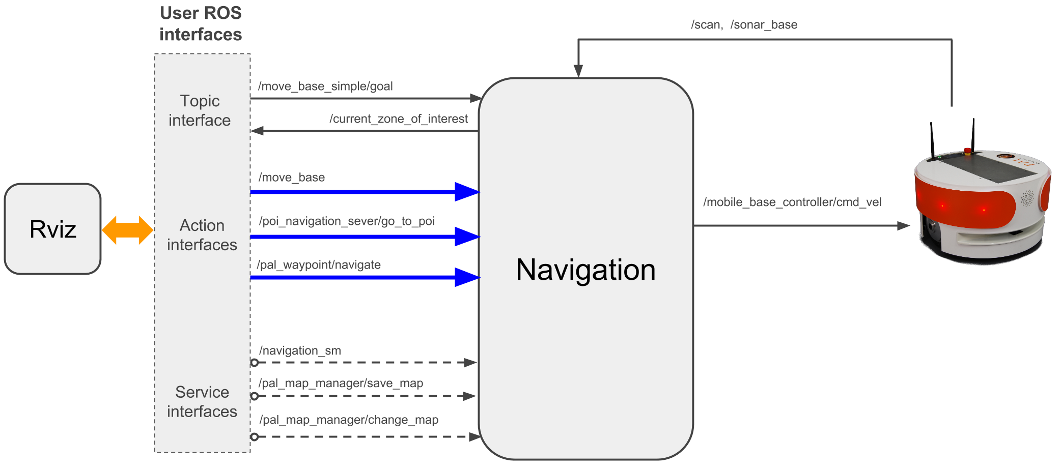
Figure: TIAGo++ navigation architecture
As can be seen, the user can communicate with the navigation software through a ROS topic, three different ROS actions and one ROS service. Note that Rviz also can use these interfaces to help the user perform navigation tasks.
The ROS nodes comprising the navigation architecture are shown in figure below. Note that nodes communicate using topics, actions and services, but also using parameters in the ROS param server (note depicted in the figure).
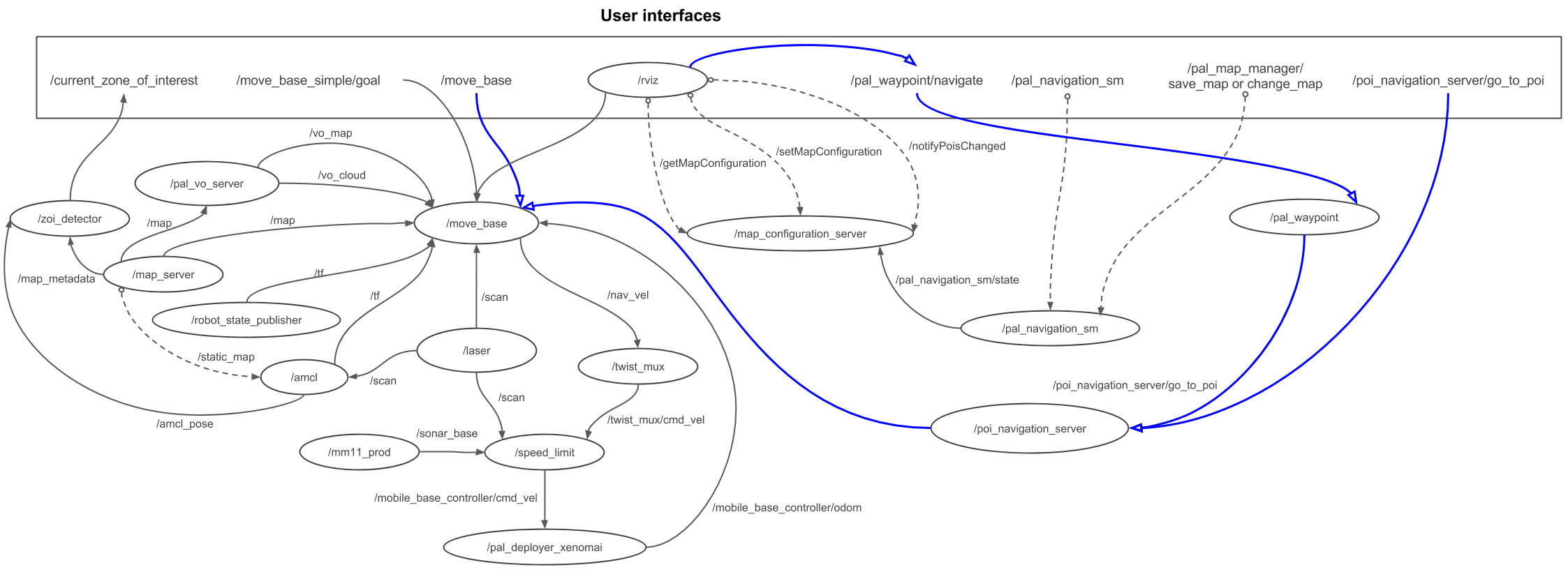
Figure: TIAGo++ navigation nodes overview
35.3 Navigation ROS API
35.3.1 Topic interfaces
/move_base_simple/goal(geometry_msgs/PoseStampled)Topic interface to send the robot to a pose specified in /map metric coordinates. Use this interface if no monitoring of the navigation status is required.
/current_zone_of_interest[2] (pal_zoi_detector/CurrentZoI)Topic to print the name of the zone of interest where the robot is at present, if any.
35.3.2 Action interfaces
/move_base(move_base_msgs/MoveBase)Action to send the robot to a pose specified in /map metric coordinates. Use of this interface is recommended when the user wants to be notified when the goal has been reached or if something fails in the process.
/poi_navigation_server/go_to_poi[3] (pal_navigation_msgs/GoToPOIAction)Action to send the robot to an existing Point Of Interest (hereafter POI) by providing its identifier. POIs can be set using the Map Editor, see 35.6 Map Editor (Premium advanced navigation package).
/pal_waypoint/navigate(pal_waypoint_msgs/DoWaypointNavigationAction)Action to make the robot visit all the POIs of a given group or subset. POIs and POI groups can be defined using the Map Editor, see 35.6 Map Editor (Premium advanced navigation package).
35.3.3 Service interface
/pal_navigation_sm(pal_navigation_msgs/Acknowledgment)Service to set the navigation mode to mapping or to localization mode.
In order to set the mapping mode:
rosservice call /pal_navigation_sm "input: 'MAP'"
In order to set the robot in localization mode:
rosservice call /pal_navigation_sm "input: 'LOC'"
In the localization mode, the robot is able to plan paths to any valid point on the map.
/pal_map_manager/save_map(pal_navigation_msgs/SaveMap)Service to save the map with a given name. Example:
rosservice call /pal_map_manager/save_map "directory: 'my_office_map'"
The directory argument is the name of the map. If empty, a timestamp will be used. The maps are stored in $HOME/.pal/pmb2_maps/configurations.
/pal_map_manager/change_map(pal_navigation_msgs/Acknowledgment)Service to choose the active map. Example:
rosservice call /pal_map_manager/change_map "input: 'my_office_map'"
35.3.4 Dynamic parameter interface
There are several dynamic parameters available to tune the navigation of the robot:
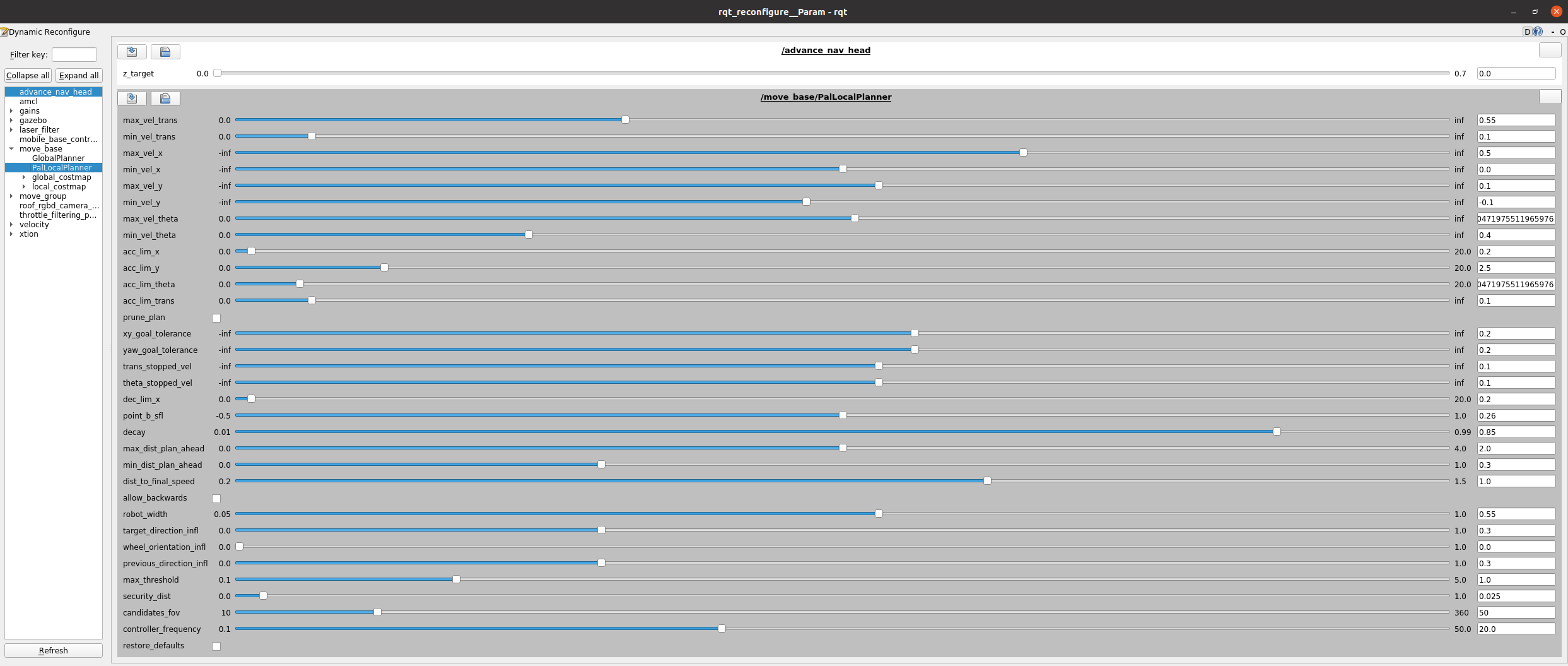
Figure: rqt_reconfigure with the dynamic parameters to tune for the navigation
This can be accessed via rqt_reconfigure on simulation or after doing the ROS_IP and ROS_MASTER_URI for the real robot:
rosrun rqt_reconfigure rqt_reconfigure
Here is a list with an explanation of the most important ones:
Under /advanced_nav_head:
z_target (Only available for the advanced navigation premium package) defines the angle of the head while navigating in advanced mode, the higher the value the more up it will look. This parameter is useful if you need to be able to see a little more ahead but keep in mind that it will not be able to detect small objects just in front of it if the value is too high. Be extra careful when tuning this parameter.
Under /move_base/PalLocalPlanner:
max_vel_x defines maximum velocity in forward motions during the navigation.
acc_lim_x defines maximum acceleration in forward motions during the navigation. This can be useful to lower in case of a slippery floor for example.
max_vel_y and acc_lim_y can also be tuned the same way only when using the omnidirectional base.
xy_goal_tolerance defines the zone of tolerance in centimeters of the navigation goal.
yaw_goal_tolerance defines the tolerance angle in radians of the navigation goal.
Under /amcl other parameters can be tuned to improve the localization:
odom_alpha1 specifies the expected noise in odometry’s rotation estimate from the rotational component of the robot’s motion.
odom_alpha2 specifies the expected noise in odometry’s rotation estimate from the translational component of the robot’s motion.
odom_alpha3 specifies the expected noise in odometry’s translation estimate from the translational component of the robot’s motion.
odom_alpha4 specifies the expected noise in odometry’s translation estimate from the rotational component of the robot’s motion.
odom_alpha5 Translation-related noise parameter (only used if the model is “omni”).
update_min_d translational movement required before performing a filter update.
update_min_a rotational movement required before performing a filter update.
35.4 SLAM and path planning in simulation
35.4.1 Mapping
The mapping system uses the readings provided by the 2D laser scanner while the robot is moved with the keyboard or joystick.
The map obtained is an Occupancy Grid Map (OGM) that can later be used to make the robot localize and navigate autonomously in the environment.
Run the simulator and mapping functionality with the following launch file :
source /opt/pal/${PAL_DISTRO}/setup.bash
roslaunch tiago_dual_0_gazebo tiago_dual_mapping.launch
The Gazebo window shown in the figure below will open and the robot should be visible in an office-like environment. Furthermore, a Rviz window will open where the robot model, sensor and map being built will be visualized.
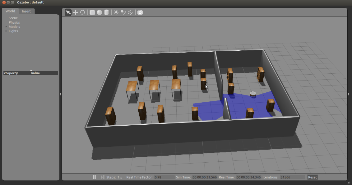
Figure: Small office world simulated in Gazebo
If you have a USB joystick plugged into your computer, it will be used to control the robot. Otherwise, the following command could be run in a terminal to control the robot with the keyboard arrow keys:
rosrun key_teleop key_teleop.py
While moving the robot around the environment, the map will start to appear in Rviz, as shown in the sequence of snapshots in the figure below.
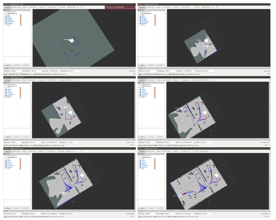
Figure: Partial maps built by the SLAM algorithm, starting (top left) and moving until a successful map is built (bottom right). The SLAM graph is represented by the nodes (red dots) and edges (blue segments).
35.4.2 Saving the map
The map can be saved manually as many times as required in the current directory by executing:
rosrun map_server map_saver
This command saves two files (as shown in the figure below): a map.pgm image file and a map.yaml configuration file. They will both be saved in the folder where the terminal is opened.
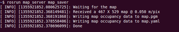
Figure: Output of map_saver call
The map.pgm file will contain a graphic representation of the map that has been built.
To save the map in the right path automatically, please use the save_map service :
rosservice call /pal_map_manager/save_map "directory: ''"
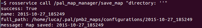
Figure: Output of map_saver call
The map will be named with the date and time it was saved, as in figure Figure: Output of map_saver call.
The save_map service will store all the map files in the path $HOME/.pal/tiago_dual_maps/configurations.
The current map in use is the one pointed to by the symbolic link $HOME/.pal/tiago_dual_maps/config.
Once mapping is finished, in order to save the map and start the localization mode, the following command should be used:
rosservice call /pal_navigation_sm "input: 'LOC'"
35.4.3 Localization and Path Planning
To run a simulation with the robot in localization and path planning mode, run:
roslaunch tiago_dual_0_gazebo tiago_dual_navigation.launch
A Gazebo window will open, with the robot in the same office-like environment, but this time the rviz window shown in figure below will show the map, localization particles, localized robot model, laser sensor readings and some virtual obstacles.
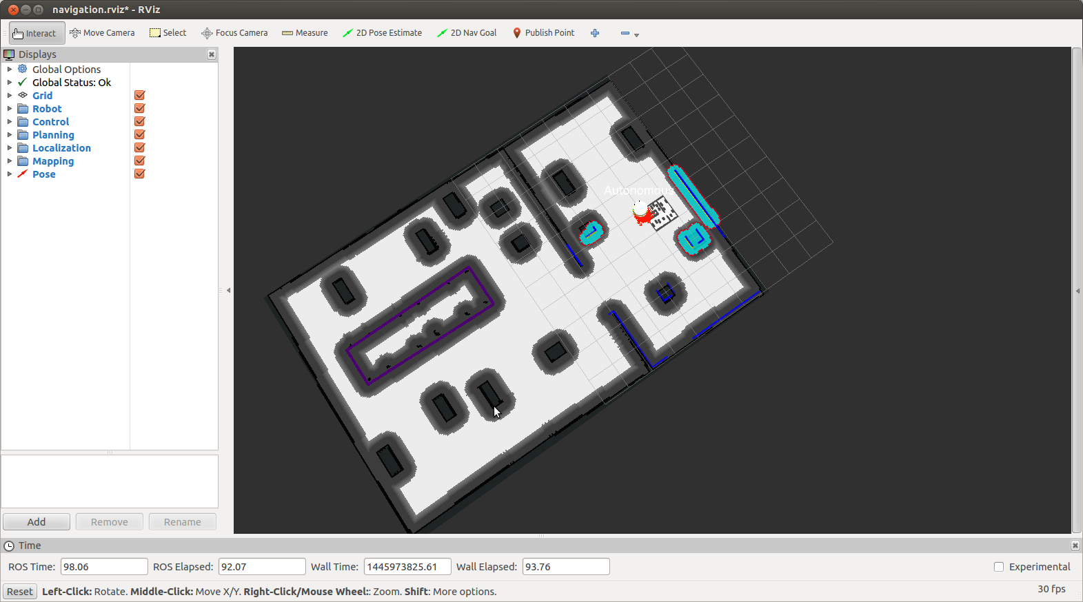
Figure: Small office world simulated navigation as visualized in rviz after running roslaunch tiago_dual_2dnav_gazebo tiago_dual_navigation.launch
To choose a goal, the user should select the “2D Nav Goal” tool in rviz (clicking on it with the left mouse button), as shown in the figure below then click on the map to select the target location the robot has to reach.
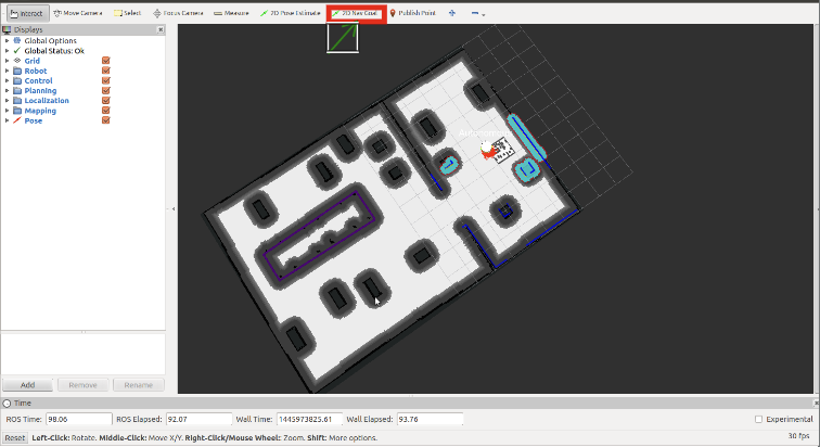
Figure: “2D Nav Goal” tool in rviz should be clocked before selecting in the map the target location the robot has to reach.
The plan will be generated and the robot will start moving along the trajectory toward the goal, as illustrated in the sequence of snapshots in the figure below:
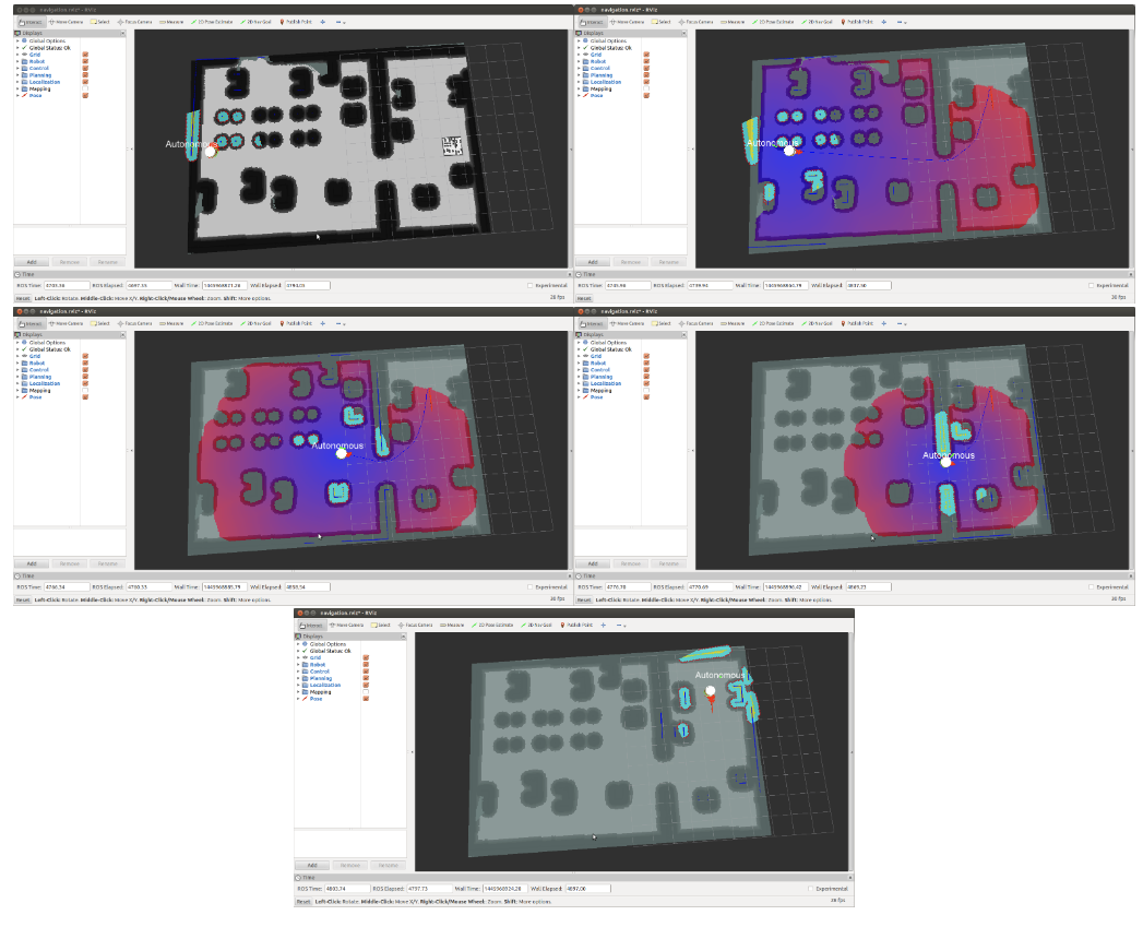
Figure: Autonomous navigation the robot continuously localizes itself on the map, plans the path for reaching the target location and executes velocity commands for following the trajectory and avoiding obstacles. Costmaps and inflated obstacles are visible.
35.5 SLAM and path planning on the robot
Important
Before continuing with the instructions of this section make sure that the robot computer is able to resolve the development computer hostname, as explained in section 12.4 ROS communication with the robot. Otherwise, some
commands will not work with the real robot due to communication failures between the robot’s computer and the development computer. For the sake of clarity and without loss of generality hereafter
we will assume that the development computer’s IP is 10.68.0.128, which will be set in the ROS_IP environmental variable when needed according to section 12.4 ROS communication with the robot. The user will have to adapt the
examples below to set the right IP address. Furthermore, make sure that the charger is not plugged into the robot’s back connector, otherwise, it will not move.
Note that when the charger is plugged into the robot’s back connector the Navigation functionality is paused for safety. The status of the functionality can be checked in the Webcommander diagnostics
tab, see figure below. Alternatively, the status can be checked in /pause_navigation topic, which reports a boolean specifying whether the functionality is paused.
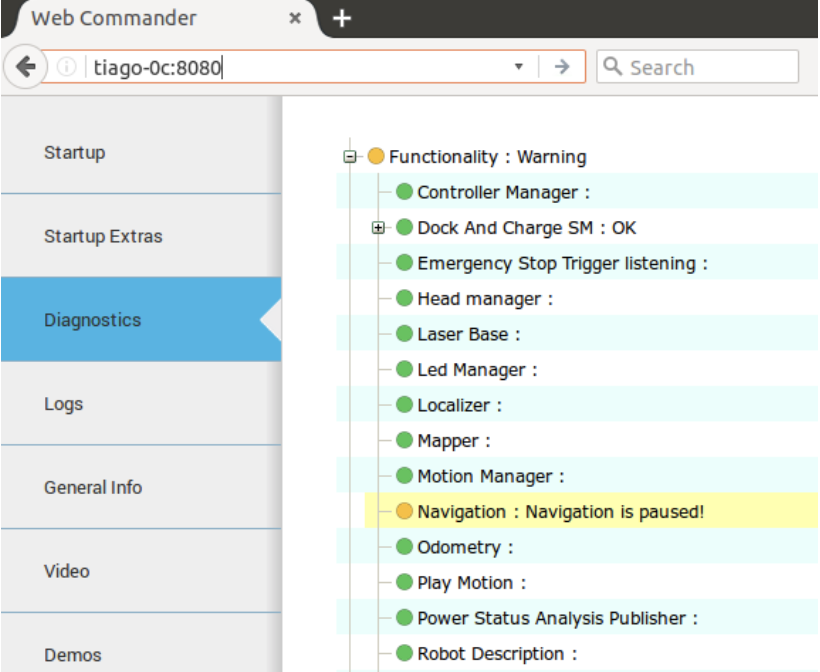
Figure: Navigation functionality paused due to connected charger.
When the robot boots, the navigation pipeline starts automatically. Furthermore, the localization mode based on the last map will be active.
On the development computer:
export ROS_MASTER_URI=http://tiago-0c:11311
export ROS_IP=10.68.0.128
rosservice call /pal_navigation_sm "input: 'MAP'"
In order to visualize the map in rviz from your development computer, run the following command:
export ROS_MASTER_URI=http://tiago-0c:11311
export ROS_IP=10.68.0.128
rosrun rviz rviz -d 'rospack find tiago_dual_2dnav'/config/rviz/navigation.rviz
When the service has finished switching between localization and mapping, you can start moving the robot around with the joystick or via key_teleop to map the environment. You can see in rviz the map creation and updates.
To create a good map you would need to go to all the places that you want to map and you can follow close loop trajectories as shown below:
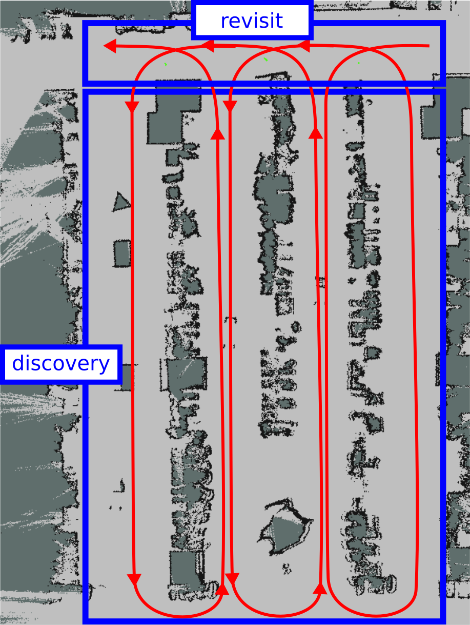
Figure: Mapping process to get a good map of the environment
35.5.1 Saving the map on the robot
The map can be saved on the development computer in the current directory by executing the following from a terminal:
export ROS_MASTER_URI=http://tiago-0c:11311
export ROS_IP=10.68.0.128
rosrun map_server map_saver
To save the map built in the robot, please use the save_map service:
export ROS_MASTER_URI=http://tiago-0c:11311
export ROS_IP=10.68.0.128
rosservice call /pal_map_manager/save_map "directory: ''"
The save_map service will store all the map files in the path
$HOME/.pal/tiago_dual_maps/configurations in the robot’s file system. The current map in use is the one pointed to by the symbolic link $HOME/.pal/tiago_dual_maps/config.
In order to automatically save the map, finish mapping and start using the map for localization and path planning, use the following command:
export ROS_MASTER_URI=http://tiago-0c:11311
export ROS_IP=10.68.0.128
rosservice call /pal_navigation_sm "input: 'LOC'"
35.5.2 Localization and path planning
Localization and path planning start automatically during boot-up. A specific rviz configuration file for navigation is provided in tiago_dual_2dnav. In order to launch rviz using this configuration file, do the following:
export ROS_MASTER_URI=http://tiago-0c:11311
export ROS_IP=10.68.0.128
rosrun rviz rviz -d 'rospack find tiago_dual_2dnav'/config/rviz/navigation.rviz
To choose a goal, the user should select the “2D Nav Goal” tool in rviz (clicking on it with the left mouse button), as shown in figure “2D Nav Goal” then click in the map to select the target location the robot has to reach.
The plan will be generated and the robot will start moving along the trajectory towards the goal, as illustrated in the sequence of snapshots in figure in autonomous navigation.
If the robot does not move, make sure that the ROS_IP variable has been set with the right IP address of the development computer.
Navigation goals can be sent programmatically to the Action Server /move_base_simple.
35.5.3 Changing the active map on the robot
When the navigation is in localization mode, any of the maps stored in $HOME/.pal/tiago_dual_maps/configurations can be selected. In order to select a map, use the following command:
ssh pal@tiago-0c
rosservice call /pal_map_manager/change_map "input: 'MAP_NAME'"
where MAP_NAME is the name of the map that we want to select.
35.6 Map Editor (Premium advanced navigation package)
As seen in the previous sections with rviz, we can easily visualize the mapping process. In the localization mode, it is then possible to send the robot to any point on the map and provide a new localization estimate when necessary.
The PAL Map Editor [4] is a rviz plugin that provides advanced navigation functionalities to rviz, including:
Downloading and uploading maps
Re-naming maps
Changing the active map
Definition of Zones Of Interest (ZOIs)
Definition of Points of Interest (POIs) and groups of POIs
Definition of Virtual Obstacles (VOs)
The information about POIs, ROIs and VOs are stored along with the map as meta-data.
A graphical joystick is also provided to remotely teleoperate TIAGo++’s mobile base.
In order to launch rviz with the Map Editor plugins, do the following:
export ROS_MASTER_URI=http://tiago-0c:11311
export ROS_IP=10.68.0.128
rosrun rviz rviz -d 'rospack find tiago_dual_2dnav'/config/rviz/advanced_navigation.rviz
In order to ensure that rviz works properly, make sure that the robot computer is able to resolve the development computer hostname, as explained in section 12.4 ROS communication with the robot.
The different plugins added to rviz are shown in the figure below:
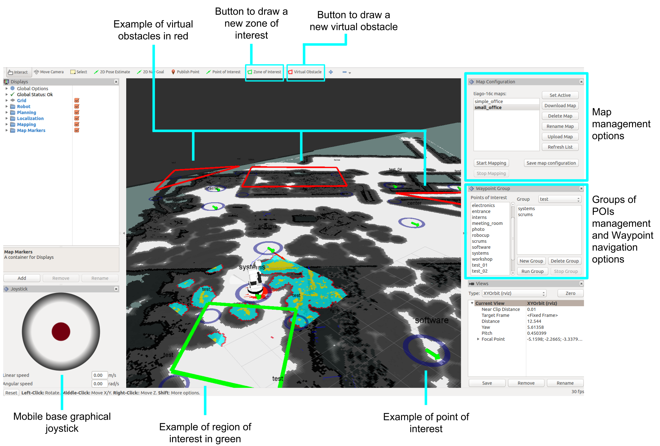
Figure: Rviz with the Map Editor plugins
35.6.1 Launching the Map Editor
In order to run the Map Editor in a development computer the following commands can be used in simulation and with a real robot.
Simulation
roslaunch tiago_dual_0_gazebo tiago_dual_navigation.launch
Real robot
export ROS_MASTER_URI=http://tiago-0c:11311
export ROS_IP=10.68.0.128
rosrun rviz rviz -d 'rospack find tiago_dual_2dnav'/config/rviz/advanced_navigation.rviz
In both cases, when running the Map Editor for the first time an example of a map will be loaded.
35.6.2 Creating a map
In order to create a new map the button Start Mapping, in the Map Configuration panel, must be pressed. The robot base can be then teleoperated using the robot’s joystick, the key_teleop package or
the graphical joystick of the Map Editor. Once the robot has mapped all the areas of interest the user has to press the Stop Mapping. This will create a new map on the robot with a name consisting of a timestamp.
The figure below shows the process of mapping in the Map Editor: on the top-right picture the previous active map
is shown. At its right the status after starting mapping. The lower row shows the map under creation and the complete map after pressing the Stop Mapping.
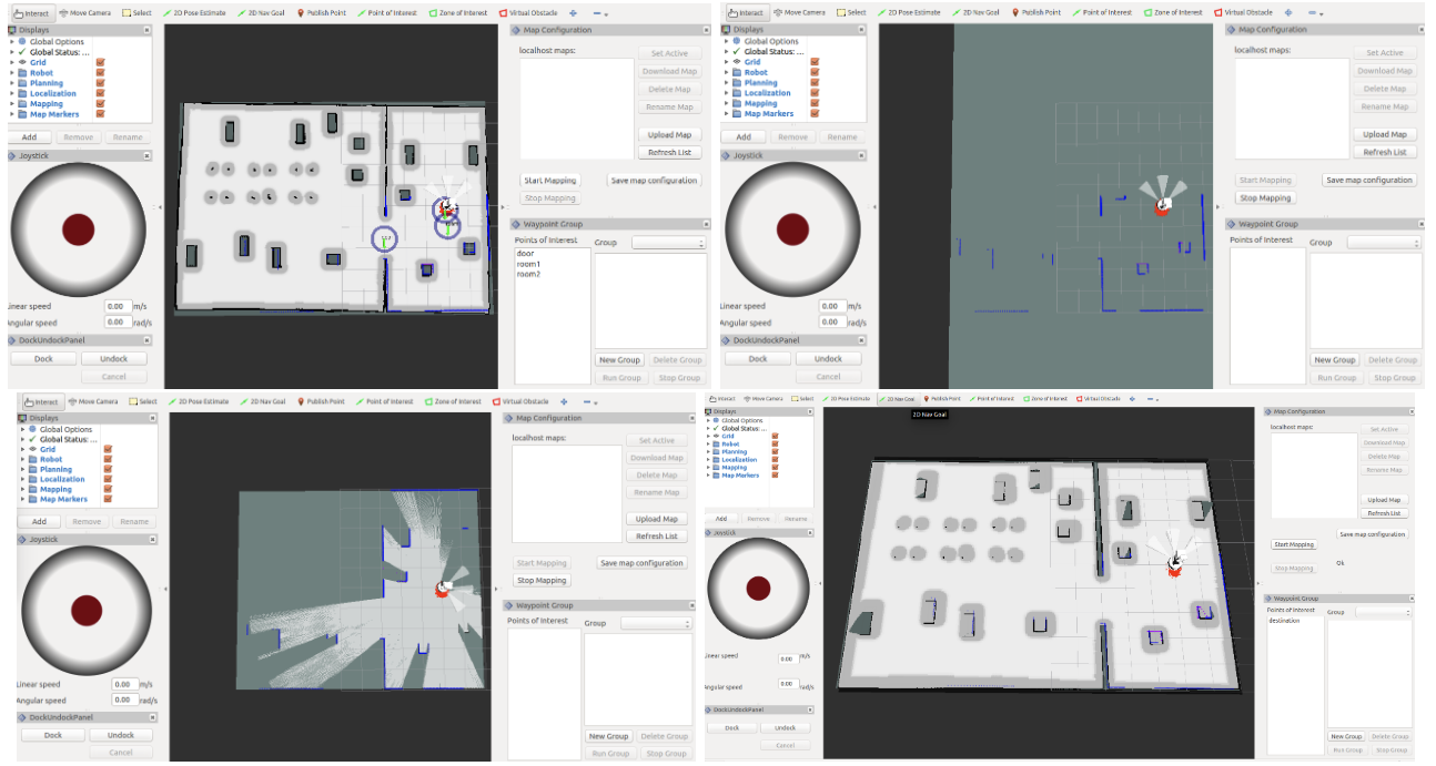
Figure: Map creation using the Map Editor
35.6.3 Managing maps
In order to list all the maps stored in the robot the button Refresh List of the Map Configuration panel must be pressed. The list of available maps will appear in the panel as shown in the figure below. Note that the one printed in bold is the active one.
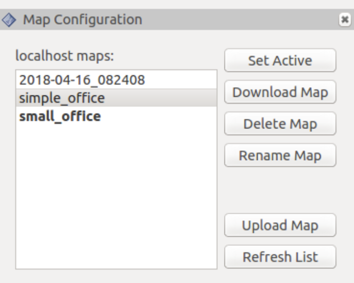
Figure: Management of maps
Map operations available are:
Set Active: the map selected in the list will be loaded and used for navigation.
Download Map: this button saves the selected map in the list in the path of the local computer running the Map Editor specified by the user.
Delete Map: removes the selected map in the robot’s computer.
Rename Map: change the name of the selected map.
Upload Map: copy a map from the local computer to the robot’s computer.
35.6.4 Defining Points of Interest
A Point of Interest is a pose in the map defined by a set of coordinates and orientation. Once a POI is defined
and stored in the map meta-data the robot can be sent to the POI using the go_to_poi action interface explained in section 35.3.2 Action interfaces
To create a new POI the button Point of Interest on the top bar of the Map Editor must be pressed.
Then move the mouse to the desired map location, press the mouse’s left button and drag the mouse to define
the orientation of the POI. Release the mouse’s button when the green arrow that will appear points to the
desired direction and sense. Afterward, a dialog requesting the name of the POI will show up as shown in
Figure: Definition of POIs. After accepting it the POI will be created. In order to get these meta-data permanently stored press Save map configuration.
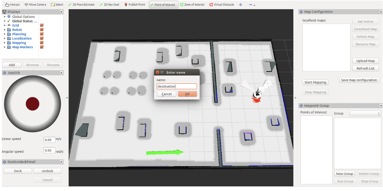
Figure: Definition of POIs
35.6.5 Defining Zones of Interest
Zones of Interest provide a simple way to have topological localization, i.e. obtain the name of the zone of the map where the robot is located. A ZOI can be defined by pressing the Zone of Interest button on the top
bar of the Map Editor. By clicking on a map point the user specifies the central position of the ZOI. Afterward, a dialog requesting the name of the zone and then another requesting how many points will be used to define
the zone will appear, see Figure: Definition of ZOIs. A green polygon with the selected number of vertices will appear on the selected map point. The user can then drag the vertices with the mouse to define the final placement of the
Zone of Interest. Note that in order to move a vertex of the zone the mouse icon must be placed on top of the blue circle, the color of the circle will vary slightly, before clicking on it and dragging it.
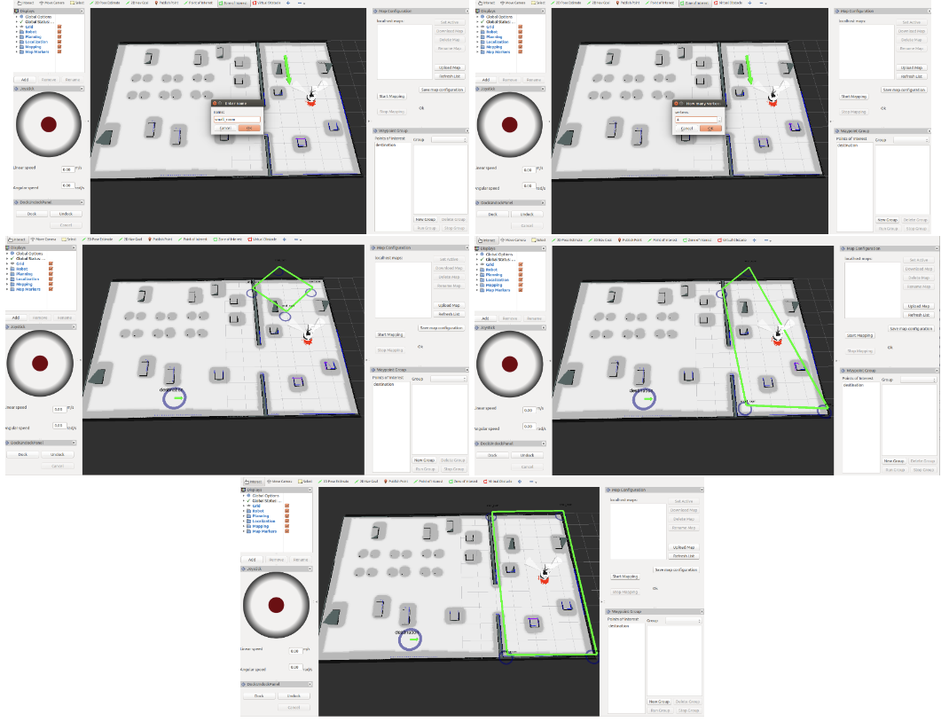
Figure: Definition of ZOIs
After all the ZOIs are defined the Save map configuration will store the corresponding map meta-data. Any time the robot enters any of the ZOIs, the topic /current_zone_of_interest will print the name of the ZOI.
35.6.6 Defining Virtual Obstacles
Virtual obstacles are of key importance to prevent some dangerous situations during navigation, like falling downstairs or colliding with obstacles not clearly visible to the robot’s sensors, and to label forbidden areas
where the robot is not allowed to enter. The VOs are created the same way as the ZOIs by pressing the Virtual Obstacle button on the top bar of the Map Editor. VOs are represented with red polygons, see
Figure: Definition of Virtual Obstacles. In order to store the meta-data defining the VOs the user must press Save map configuration.
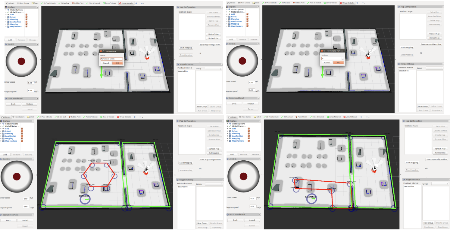
Figure: Definition of Virtual Obstacles
35.6.7 Defining Groups of POIs
After defining POIs the user can define groups of different POIs. A group of POIs can be run so that the robot visits in sequence all the POIs in the group. To create groups of POIs the panel Waypoint Group is
provided. The list on the left of the panel shows all the POIs created. First press New Group to define a new group of POIs. A dialog requesting the name of the group will appear, see Figure: Definition of POI groups. In order to add POIs first
select the POI on the left list and drag it to the panel of its right. The same POI can be set to a group multiple times. When the group contains all the desired POIs press the Save map configuration.
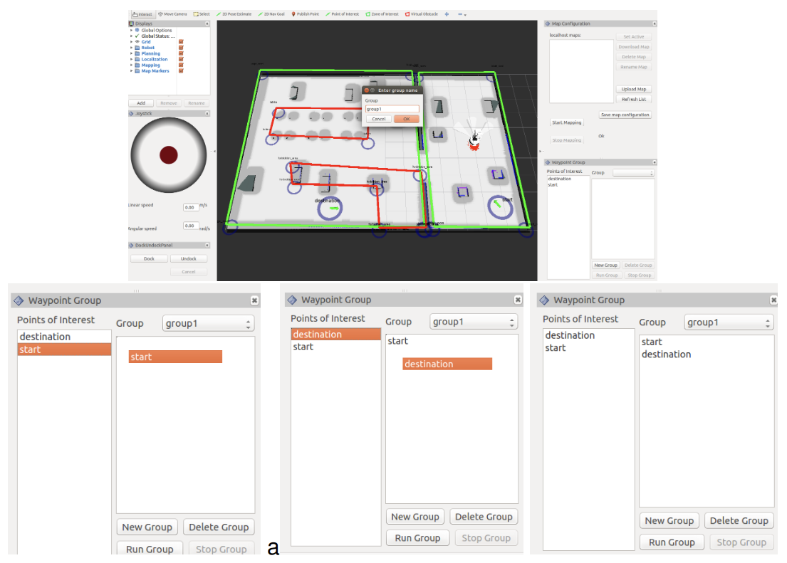
Figure: Definition of POI groups
The robot will visit in sequence all the POIs in a group when the group is selected in the dropdown list named Group and when pressing the Run Group. The task can be canceled at any time by pressing the
Stop group. The Figure: Running a POI group shows the robot running a group of 2 POIs and avoiding VOs. In order to run a group of POIs the action interface /pal_waypoint/navigate is available.
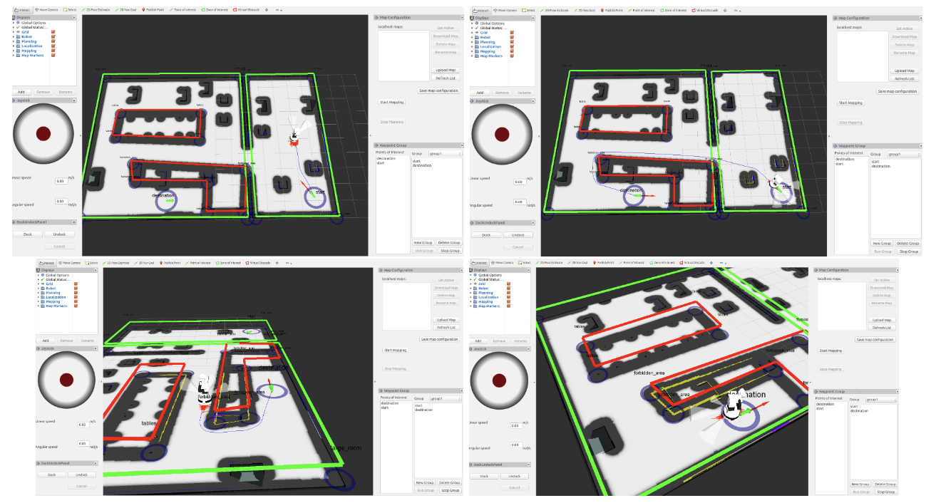
Figure: Running a POI group
35.6.8 Modifying map meta-data
The POIs, ZOIs and VOs can be modified at any time or removed by placing the mouse icon on top of their blue circle and clicking on the right button. A popup menu will appear providing different options: removing the POI or in the case of ZOIs and VOs adding a new vertex, removing a vertex or removing the whole ZOI or VO.
After any modification of the POIs, ZOIs or VOs remember to press Save map configuration to store the changes permanently in the map.
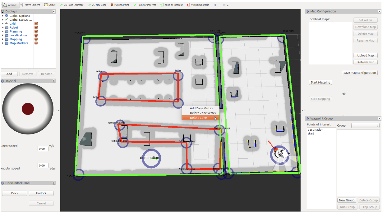
Figure: Example of meta-data modification
35.7 Obstacle avoidance with the RGB-D camera
The Advanced Navigation [5] package provides obstacle avoidance using the depth information of the RGB-D camera on TIAGo++’s head. This is very important to safely navigate by avoiding obstacles that cannot be detected by the laser scanner but by the camera. A good example of objects that can compromise navigation safety are tables. Note that the laser can only detect the leg(s) of the table and the robot may collide with it when navigating close to it. Furthermore, a navigation plan crossing the table can be even generated by the global planner.
The obstacle avoidance using the RGB-D camera offers a good solution to these problems and that is why it is enabled by default. The feature is implemented as follows: any time that the robot is requested to go to a map point the following behavior starts:
The
pal_head_managernode is disabled to prevent undesired head motions during the navigationThe torso is raised a bit and the head is lowered so that potential obstacles in front of the robot fall inside the camera field of view, see Figure: Robot pose adopted to improve RGB-D based obstacle avoidance performance
The point cloud provided by the camera will be continuously used in order that obstacles detected by the camera are taken into account
Both the torso and the camera will remain in this configuration until the robot reaches the goal position on the map. Then, the
pal_head_managernode is enabled again.
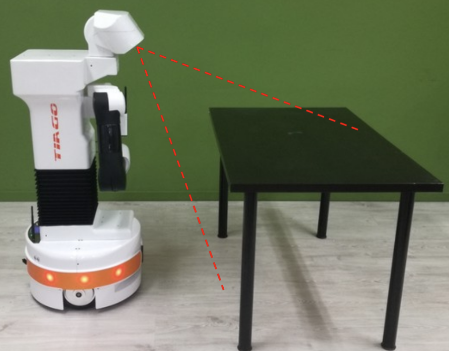
Figure: Robot pose adopted to improve RGB-D based obstacle avoidance performance
The figure below presents an example of a simulation where using the camera for obstacle avoidance is mandatory. Note that the robot is in front of a table: initially only the legs are detected by the laser. The robot is sent to a map point at the other side of the table. The first planned path involves crossing the table, but when the camera detects the table plane the obstacle is added to the costmap and the planner looks for an alternative path. This kind of navigation example fails when using only the laser for obstacle avoidance.
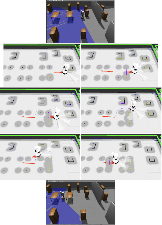
Figure: Obstacle avoidance using the camera point cloud
35.7.1 Disabling obstacle avoidance with the RGB-D camera
In case the user needs to disable this feature the following commands can be executed in the robot:
ssh pal@tiago-0c
pal-stop navigation_camera_mgr
rosrun dynamic_reconfigure dynparam set /move_base/local_costmap/obstacle_rgbd_layer enabled false
rosrun dynamic_reconfigure dynparam set /move_base/global_costmap/obstacle_rgbd_layer enabled false
35.7.2 Enabling obstacle avoidance with the RGB-D camera
In order to re-enabling this feature the following commands can be executed in the robot:
ssh pal@tiago-0c
pal-start navigation_camera_mgr
rosrun dynamic_reconfigure dynparam set /move_base/local_costmap/obstacle_rgbd_layer enabled true
rosrun dynamic_reconfigure dynparam set /move_base/global_costmap/obstacle_rgbd_layer enabled true
36 Dock station
36.1 Overview
Depending on the version acquired, your TIAGo Base may include a dock station that allows the robot to recharge itself automatically. This section will describe the components of the dock station and how to use integrate it with your algorithms.
36.2 The Dock Station Hardware
The dock is composed by a metal structure containing basically a pattern to be detected by the TIAGo++’s LIDAR sensor, a connector to the external charger and the power contacts that will transmit the energy to the robot, as shown in figure below. The dock also has tabs that can be screwed to the floor or wall to rigidly fix it, although this operation is not necesary. It is important to emphasize that, although the charger possesses several security protections, the user should not touch or meddle with the power contacts, for safety reasons.
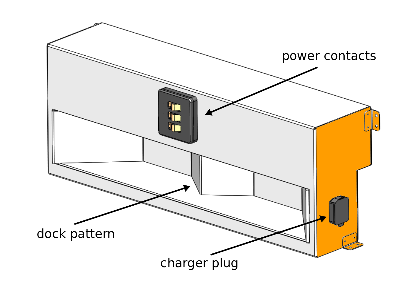
Figure: The dock station
36.3 Installation
The dock station should be preferably mounted against a hard surface, to avoid the robot displacing it while doing a docking manoeuvre. The power charger must be plugged in the respective plug. The user must also assure that no objects are present in the dock surroundings, that could interfere with the docking manoeuvre.
36.4 Docking Algorithm
When the robot is asked to go to the dock station, it activates two services in parallel. The first is responsable for the pattern detection, while the second performs the servoing to reach the power contacts:
pattern detector: the robot is capable of detecting the pattern up to 1 meters from the LIDAR sensor and with an orientation angle of ± 10º.
servoing manoeuvre: it comprises two steps, where first the robot aligns itself with the power contacts and, secondly, advances until the contact is made or a timeout occurs (in the case the dock station is not powered, or the contact fails for example).
The figure below illustrates the requirements for the docking maneouvre.
Once the robot is docked, it will block most velocity commands sent to the base, in order to avoid manoeuvres that could possibly damage the robot or the dock station. There are only two ways of moving the robot after is it docked: by doing an undock manoeuvre, or using the gamepad, which can override all velocity commands.
Warning
It is the sole responsability of the user to operate safely the robot with the gamepad after the robot has reached the dock station.
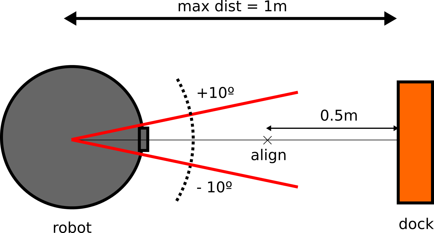
Figure: The docking specifications
36.5 Usage
The dock/undock manoeuvres are available through two different action servers that can be activated by using the provided rviz plugin or directly through the action server interface.
36.5.1 Dock/Undock using RViz plugins
A dock/undock panel is available as an RViz plugin, that can be added to any RViz configuration by going to the menu Panels -> Add New Panel and then chosing the DockUndockPanel. There is also a preconfigured rviz file that is shipped with the robot and can be loaded with the following command:
export ROS_MASTER_URI=http://tiago-0c:11311
export ROS_IP=10.68.0.128
rosrun rviz rviz -d `rospack find tiago_2dnav`/config/rviz/advanced_navigation.rviz
Make sure to use your robot’s serial number when exporting the ROS_MASTER_URI variable and to set your
development computer’s IP when exporting ROS_IP as explained in section 12.4 ROS communication with the robot.
The figure below shows the layout of the panel.
Once the user has positioned the robot within the tolerances specified previously, they can click the Dock button to perform a docking manoeuvre. It is possible to cancel the docking manoeuvre at any time by clicking the Cancel button. Similarly, the robot can be moved out from the dock by clicking the Undock button. A status message will be shown beside the Cancel button, informing the user of the status of the action requested.
Note
The robot will only accept an undock order if it was previously docked, otherwise the action request will be rejected.
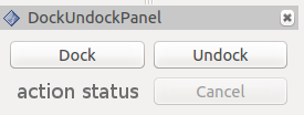
Figure: rviz plugin
36.5.2 Dock/Undock using action client
ROS provides an action client interface that can be used to communicate with the action servers responsible for the dock and undock manoeuvres. To run the action client, enter the following command to perform the docking manoeuvre:
export ROS_MASTER_URI=http://tiago-0c:11311
export ROS_IP=10.68.0.128
# For ROS Melodic
rosrun actionlib axclient.py /go_and_dock

# For ROS Noetic
rosrun actionlib_tools axclient.py /go_and_dock
and for the undocking manoeuvre:
export ROS_MASTER_URI=http://tiago-0c:11311
export ROS_IP=10.68.0.128
# For ROS Melodic
rosrun actionlib axclient.py /undocker_server

# For ROS Noetic
rosrun actionlib_tools axclient.py /undocker_server
After any of the previous commands are executed, a panel will pop up. The last figure shows both the /go_and_dock and the /undocker_server panels.
Note
For the docking action client, the field use_current_pose should be set to True, otherwise the action will fail (this field is not needed for the /undocker_server). In this interface, the button SEND GOAL will start the docking (or undocking) manoeuvre. As before, the CANCEL GOAL button will abort the action, and the status of both the server and the goal will be displayed in the bottom of the panel.
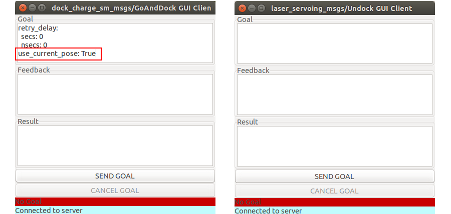
Figure: The action client for the docking and undocking manoeuvres.
36.5.3 Dock/Undock code example
Finally, the user can interface with the action servers directly by code, in either Python or C++. There is plenty examples of the usage of action clients in ROS Wiki. Bellow there is a very simple example in Python code, that connects and sends a goal to the /go_and_dock server. Note that the field goal.use_current_pose (line 19) is set to False, as in the previous example.
1. #!  / usr/bin / env python
2. import rospy
3. import rospkg
4. import  actionlib
5.
6. from dock_charge_sm_msgs.msg import GoAndDockAction, GoAndDockGoal
7. from std_msgs.msg import Bool
8.
9. class  SimpleDock():
10.    def  __init__(self) :
11.
12.       rospy.init_node('simple_dock')
13.       self.dock_checker_sub = rospy.Subscriber("/power/is_docked", Bool, self.is_docked_cb)
14.       self.is_docked = False
15.
16.    def go_and_dock_client(self):
17.
18.       goal = GoAndDockGoal()
19.       goal.use_current_pose = True
20.       self.dock_client  =  actionlib.SimpleActionClient("go_and_dock", GoAndDockAction)
21.       self.dock_client.wait_for_server()
22.       self.dock_client.send_goal(goal)
23.       rospy.loginfo("goalsenttogoanddockserver")
24.
25.    def is_docked_cb(self, is_docked):
26.       if(is_docked.data):
27.          self.dock_checker_sub.unregister()
28.          rospy.loginfo("simpledocker:therobotisdocked!")
29.          quit()
30.
31. if  __name__ == '__main__':
32.     try:
33.        sd = SimpleDock()
34.        sd.go_and_dock_client()
35.        rospy.spin ()
36.     except rospy.ROSInterruptException:
37.        print ( "programinterruptedbeforecompletion")
37 Motion planning with MoveIt!
37.1 Overview
This section covers how to perform collision-free motions on TIAGo using the graphical interface of MoveIt!. Collision-free motion planning is performed by chaining a probabilistic sampling-based motion planner with a trajectory filter for smoothing and path simplification.
For more information, C++ API documentation and tutorials, go to the following website: http://moveit.ros.org.
37.2 Getting started with the MoveIt! graphical user interface in simulation
This subsection provides a brief introduction to some basic use cases of MoveIt!. For testing, a TIAGo++ simulation is recommended. In order to run it with the real robot please refer to the 37.3 MoveIt! with the real robot.
Start a simulation:
roslaunch tiago_dual_0_gazebo tiago_dual_gazebo.launch world:=empty
Start MoveIt! with the GUI in another terminal:
roslaunch tiago_dual_moveit_config moveit_rviz.launch config:=true
This command will start the motion planning services along with visualization. Do not close this terminal.
The GUI is rviz with a custom plugin for executing and visualizing motion planning.
MoveIt! uses planning groups to generate solutions for different kinematic chains. The figure below shows that by selecting different planning groups, the GUI shows only the relevant “flying end-effectors”.
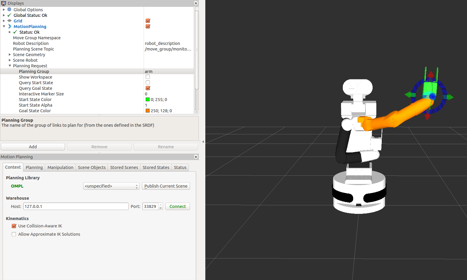
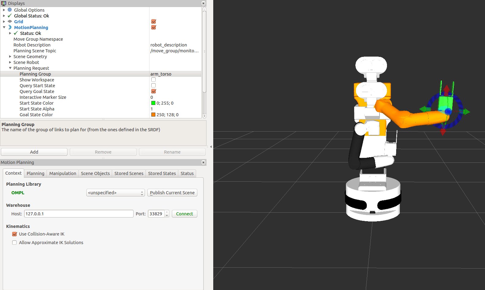
Figure: MoveIt! graphical interface in rviz. TIAGo++ with the planning group arm (top) and with the planning group arm_torso (bottom).
In order to use motion planning, a Start State and Goal State has to be known. To do this with the MoveIt! GUI, navigate to the tab called “Planning” in the display called MotionPlanning. On this tab, further nested tabs provide the functionality to update Start State and Goal State, as depicted in the figure below (Figure: Tab to set start state).
By clicking the “Update” button of the Goal State, new poses can be randomized. The Figure: Random poses generated with the GUI shows a few randomly generated poses.
The sequence of images in Figure: Sequence of plan shows the result of clicking the “Update” goal pose with random inrviz, then clicking “Plan and Execute” in the simulator. Rviz will visualize the plan before executing.
The GUI also allows the operator to define goal poses using the “flying end-effector” method. As shown in the first two figures in the subsection 37.2.1 The planning environment of MoveIt!, the 6 DoF pose of the end-effector can be defined by using the visual marker attached. The red, green and blue arrows define the translation of x, y and z coordinates respectively, and the colored rings define the rotation around these axes following the same logic.
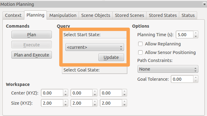
Figure: Tab to set start state (point 3)
Figure: Tab to set goal state
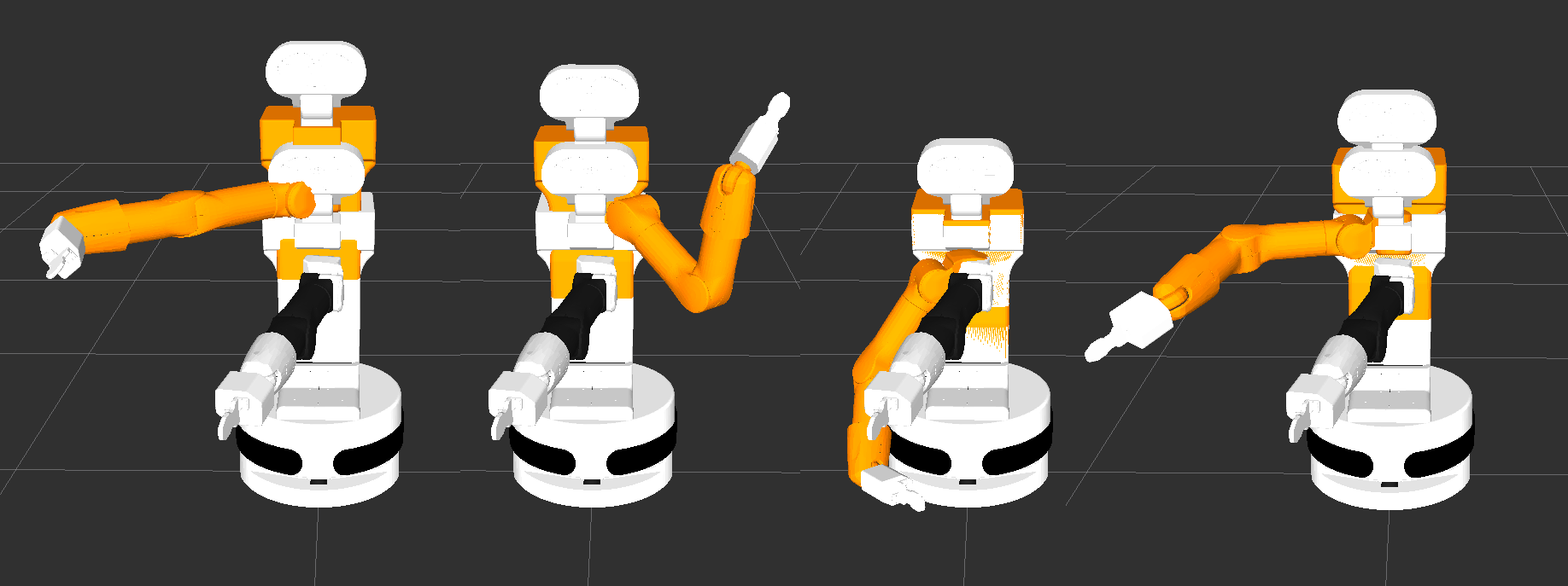
Figure: Random poses generated with the GUI (point 4)
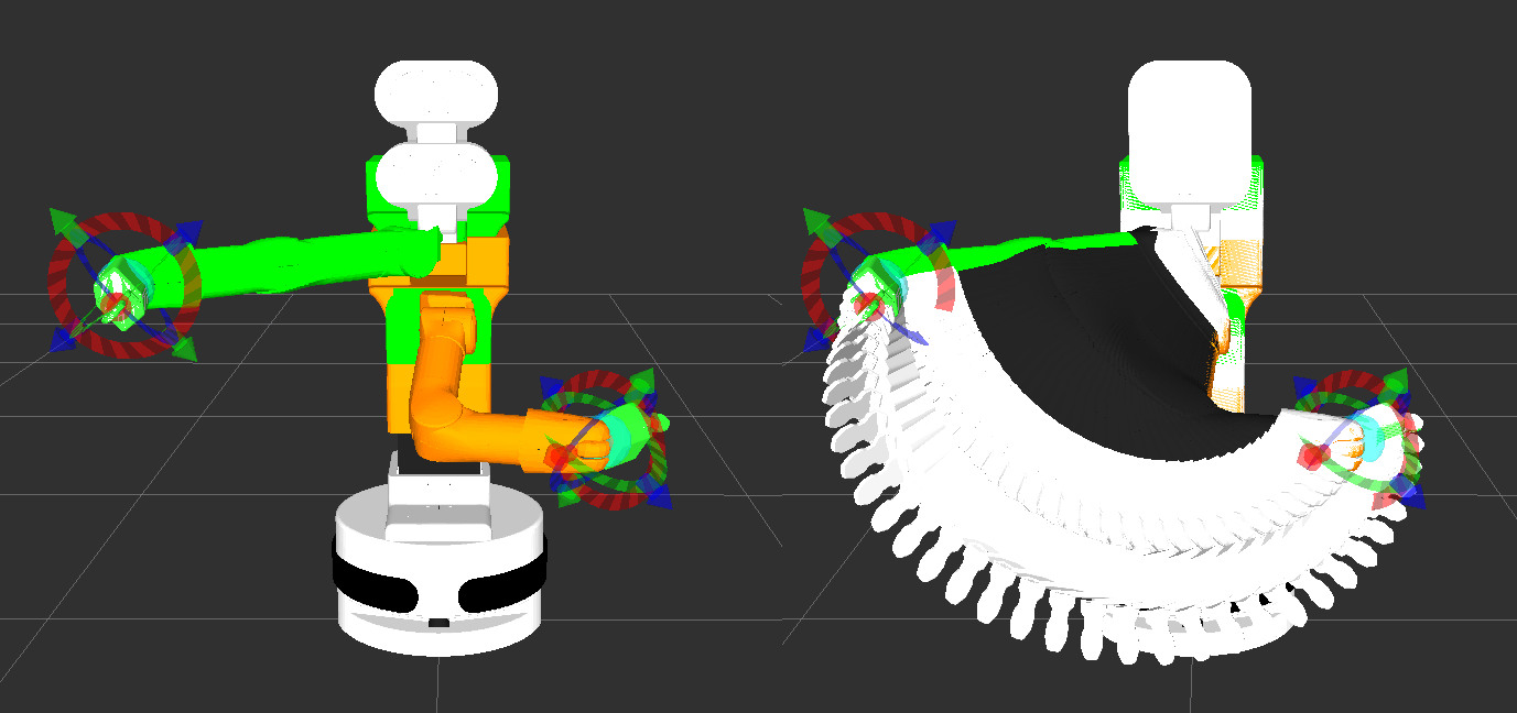
Figure: Sequence of plan (point 5)
37.2.1 The planning environment of MoveIt!
For a complete description, see see this link.
Adding a collision object to the motion planning environment will result in plans avoiding collisions with these objects. Such an operation can be done using the C++ or Python API, or with the GUI presented in the previous subsection For this demonstration, we are going to use the GUI.
1. To add such an object to the planning environment, navigate to the “Scene objects” tab in the planning environment window, then click “Import file” and navigate to the tiago_dual_description package, where the mesh of the head can be found in the meshes head folder, as shown in the last three figures of this subsection.
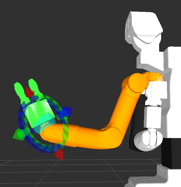
Figure: End-effector tool
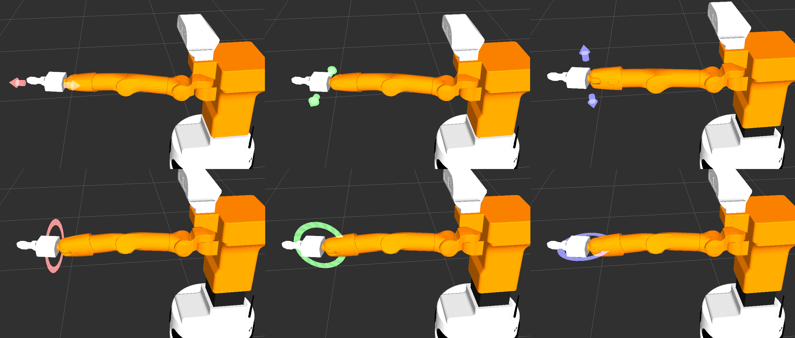
Figure: Usage of each DoF
Place the mesh close to front of the arm, then select the planning group “arm_torso”.
Move the end-effector using the “flying end-effector” to a goal position like the one shown on the first figure of the 37.3 MoveIt! with the real robot subsection. Make sure that no body part is in red, which would mean that MoveIt! detected a collision in the goal position. Goals which result in a collision state will not be planned at all by MoveIt!.
(Optional) To execute such a motion, go the “Context” tab and click “Publish current scene”. This is necessary for the planning environment in the GUI to be moved to the one used by MoveIt! for planning. Go to the “Planning” tab again, and now move the arm to a position. Since this setup can be a very complex one for the planner, it might fail at the first attempt. Keep re-planning until it is succesful. A succesful plan for the current example is shown in Figure: Example of plan found with the object in the scene.
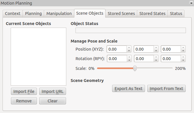
Figure: Scene objects tab
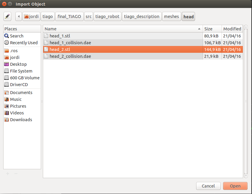
Figure: Select the mesh
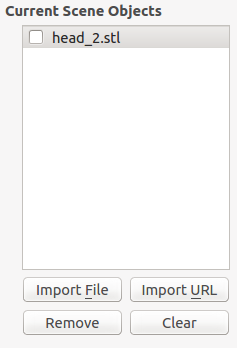
Figure: Object listed in scene objects
37.2.2 End test
To close the MoveIt! GUI, hit Ctrl-C in the terminal used in step 2. The running instance of Gazebo` can be
used for further work, but keep in mind that the robot will remain in the last pose it was sent to.
37.3 MoveIt! with the real robot
In order to run the examples explained above with the real robot the MoveIt! graphical interface has to be launched from a development computer as follows:
export ROS_MASTER_URI=http://tiago-0c:11311
export ROS_IP=10.68.0.128
roslaunch tiago_dual_moveit_config moveit_rviz.launch config:=true
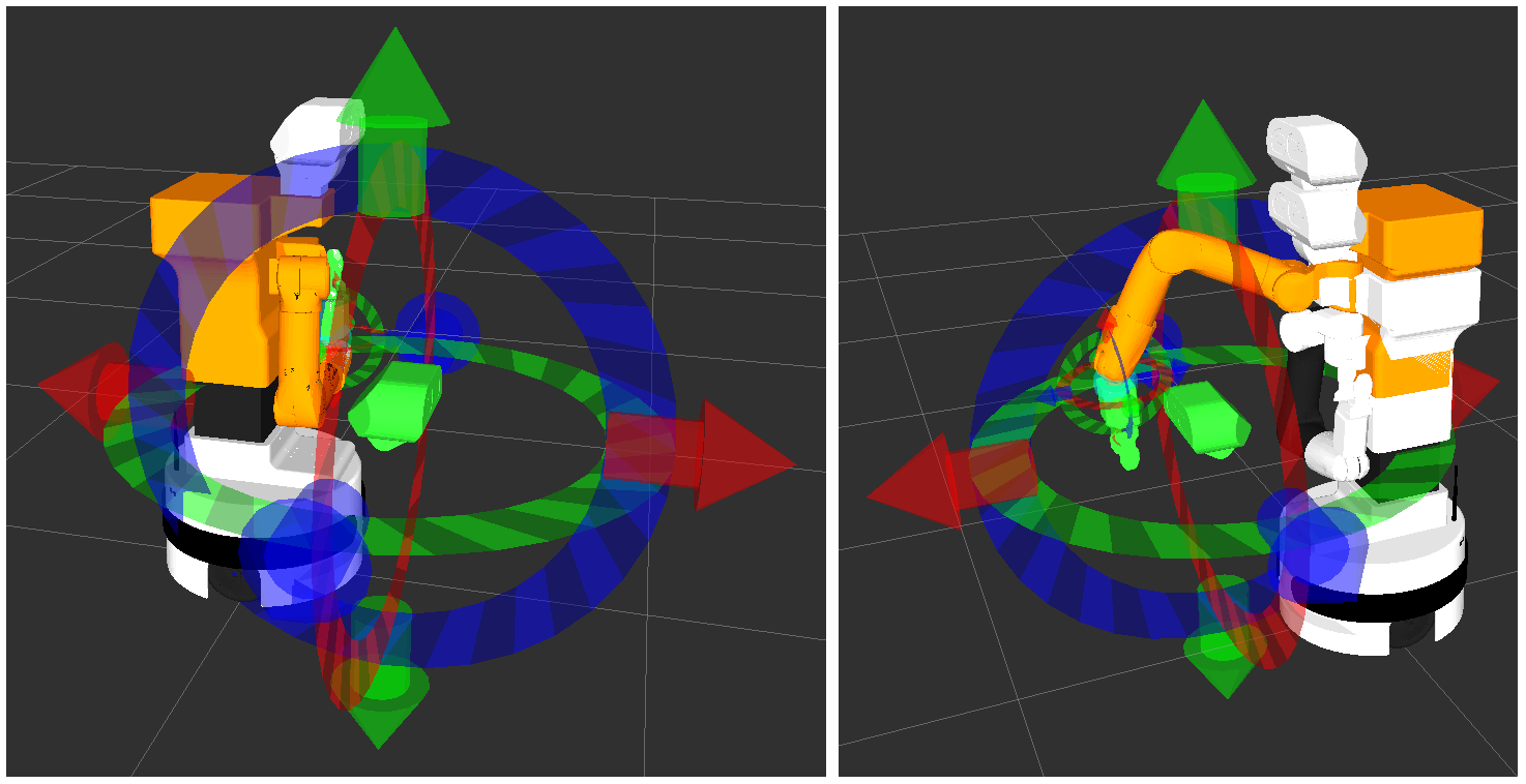
Figure: Example with an object in the scene. Initial pose (left) and goal pose (right).
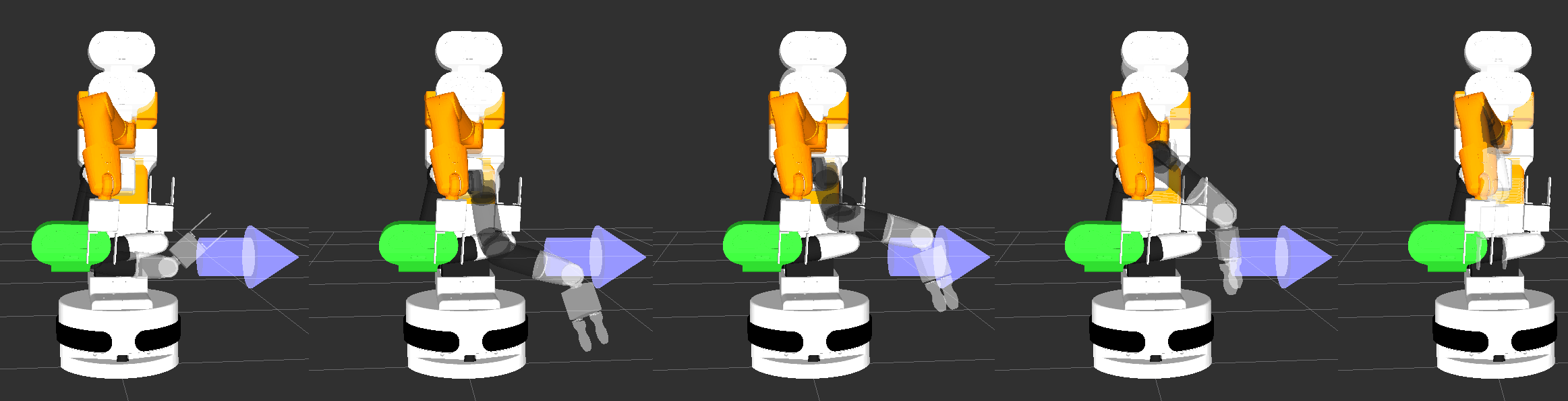
Figure: Example of plan found with the object in the scene.
Make sure to use your robot’s serial number when exporting the ROS_MASTER_URI variable and to set your development computer’s IP when exporting ROS_IP as explained in the section 12.4 ROS communication with the robot.
38 Facial perception
38.1 Overview
This chapter presents the software package for face and emotion recognition included in TIAGo++ [6].
Face and emotion recognition are implemented on top of the Verilook Face SDK provided by Neurotechnolgy.
The ROS package implementing facial perception subscribes to /xtion/rgb/image_raw image and processes this topic at 3 Hz in order to provide the following information:
Multiple face detection
3D position estimation
Gender classification with confidence estimation
Face recognition with matching confidence
Facial attributes: eye position and expression
Emotion confidences for six basic emotions
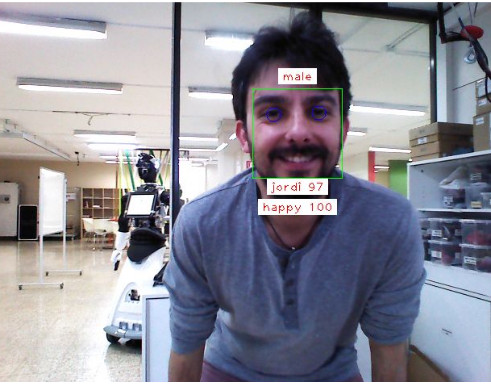
Figure: Face processing example
38.2 Facial perception ROS API
38.2.1 Topic interfaces
/pal_face/faces (pal_detection_msgs/FaceDetections)
Array of face data found in the last processed image
/pal_face/debug (sensor_msgs/Image)
Last processed image with overlayed face data: face ROIs, gender, facial features, name and emotion. In order to visualize the debug image, enter the following command from a development computer:
export ROS_MASTER_URI=http://tiago-0c:11311
rosrun image_view image_view image:=/pal_face/debug
_image_transport:=compressed
38.2.2 Service interface
/pal_face/set_database (pal_detection_msgs/SetDatabase)
Service to select the active database in the robot.
For example, in order to select a database named test_face and empty its contents, if any:
rosservice call /pal_face/set_database test_face True
In order to select an existing database named office_faces without emptying its contents:
rosservice call /pal_face/set_database office_faces False
/pal_face/start_enrollment (pal_detection_msgs/StartEnrollment)
To start learning a new face, select a database and give the name of the person as argument.
As an example, to start learning the face of Anthony:
rosservice call /pal_face/start_enrollment Anthony
During enrollment it is important that the person stands in front of the robot looking at its camera, moving
slightly their head to different distances, i.e. between 0.5 and 1.5 m, and changing their facial expression.
Face samples of the person will be gathered until /pal_face/stop_enrollment is called. An enrollment of 20-30 seconds should be enough.
/pal_face/stop_enrollment (pal_detection_msgs/StopEnrollment)
Service to stop learning a new face:
rosservice call /pal_face/stop_enrollment
During enrollment, it is important that the person stands in front of the robot looking at its camera, moving their head slightly to different distances, i.e. between 0.5 and 1.5 m, while changing their facial expression.
/pal_face/recognizer (pal_detection_msgs/Recognizer)
Service to enable or disable the face recognition. By default, the recognizer is disabled.
In order to enable the recognizer, a minimum matching confidence must be specified:
rosservice call /pal_face/recognizer True 60
Only detected faces matched to a face in the database with confidence greater or equal to the one specified will be reported.
In order to disable the recognizer:
rosservice call /pal_face/recognizer False 0
38.3 Face perception guidelines
In order to improve the performance of facial perception and to ensure its correct behavior, some basic guidelines have to be taken into account:
Do not have the robot looking at backlight, i.e. out of a window or towards an indoor lamp. The brightness of the light source will cause high contrast in the images, so that faces may be too dark to be detected.
Best performance is achieved when the subjects are enrolled and recognized at a distance of between 0.5 and 1.2 m from the camera. The further away the person, the worse recognition confidences will be obtained.
When enrolling a new person in a database, it is mandatory that no other faces appear in the image. Otherwise, the stored face data will contain features of both people and the recognition will fail.
In order to reduce the CPU load, the face recognizer should be disabled when possible.
39 Speech recognition
39.1 Overview
This chapter presents the software package for online speech recognition included in TIAGo++ [7].
When enabled, the ROS package that implements speech recognition captures audio from the robot’s microphones and sends it to the recognizers for processing. It returns recognized speech.
It has the following features:
Continuous speech recognition.
Recognition after hearing a special keyword.
Ability to use multiple speech recognizers.
- Current recognizers implemented:
Google Cloud Speech API in 80 languages, accepts hint phrases to the recognizer for commonly spoken phrases.
DeepSpeech a TensorFlow implementation of Baidu’s DeepSpeech architecture trained on American English.
39.2 Requirements
Speech Recognition Premium Software Package.
An appropriate level of ambient noise. The noisier the environment, the worse the recognition results will be.
- Google Cloud Speech requirements:
TIAGo++ must be connected to the internet and able to reach Google’s servers.
A valid Google Cloud Speech account. See 39.7 Google Cloud Speech account creation .
- DeepSpeech requirements:
NVIDIA Jetson TX2
39.3 Speech Recognition ROS API
39.3.1 Action interface
/kw_activated_asr (speech_multi_recognizer/KeywordActivatedASR.action)
This action starts the speech recognition, with optional keyword triggering.
The goal message includes the following data:
language: A BCP47 language tag. For instance en-US.
skip_keyword: If false (default value), will wait until the special keyword is understood using an offline recognition engine. After detecting the keyword, it will listen and perform one recognition with the online engines.
preferred_phrases: A list of phrases that are most likely to be recognized (provided to the online recognizer, if it supports it).
The feedback message includes the following data:
recognition_results: A list of strings with the recognition, if any. If multiple recognizer engines are configured, it will contain one entry per recognizer that performed a successful recognition.
There is no result message - the action ends when the user aborts. While active, it will perform continuous speech recognition.
Note
DeepSpeech recognizer only supports the speech recognition in English, so the language param in the action interface does no effect to the recognition.
39.4 Recognizer behaviour
The following pseudo code ilustrates how the speech recognizer operates.
while goal == active:
        if not skip_keyword:
                wait_for_keyword()  <--- OFFLINE (free)
        listen_to_one_sentence()
        recognize_sentence()        <--- ONLINE (paid)
        send_action_feedback()
39.5 Special keyword
The keyword to enable the speech recognition by default is ”Hey Tiago”.
39.6 Configuration
This system can be configured via yaml files in the multimedia computer.
The application will try to load the file at:
$HOME/.pal/pal_audio_cfg_base/speech_recognition.yaml
If it doesn’t exist, it will look for the file at:
rospack find pal_audio_cfg_base`/config/speech_recognition.yaml
This file contains the following parameters:
device_name Name of the device to use for recording (ie: hw:0,0)
keyword_model Absolute path to the Snowboy model, or the name of a file inside the config directory of the snowboy catkin package.
keyword_recognized_text Text the robot will say after recognizing the keyword.
keyword_sensitivity Sensitivity of the keyword recognizer, lower means more false positive, higher can make it more difficult to detect.
39.7 Google Cloud Speech account creation
At the time this manual was written, Google offers 60 minutes of online speech recognition per month, free of charge. After that, your account will be billed according to your use of their recognition engine. For more information, refer to https://cloud.google.com/speech/pricing
Click on “Try it free”.
Log in and agree to the terms and conditions.
Complete your personal/company information and add a payment method.
You will be presented with your Dashboard. If not, click here (https://console.cloud.google.com/home/dashboard).
Enter “Speech API” in the search bar in the middle of the screen and click on it.
Click on Enable to enable the Google Cloud Speech API.
Go to the Credentials page (https://console.cloud.google.com/apis/credentials)
Click on “Create credentials,” and on the dropdown menu select: “Service account key”.
You’ll be asked to create a service account. Fill in the required info and set Role to Project -> Owner.
A .json file will be downloaded to your computer. STORE THIS FILE SECURELY: IT IS THE ONLY COPY.
Copy this file to TIAGo++’s
/home/pal/.pal/gcloud_credentials.jsonGoogle will now use these credentials.
40 Whole Body Control
40.1 Overview
The Whole Body Control (WBC) [8] is PAL’s implementation of the Stack of Tasks [9]. It includes a hierarchical quadratic solver, running at 100 Hz, able to accomplish different tasks with different priorities assigned to each. In order to accomplish the tasks, the WBC takes control of all TIAGo++’s upper-body joints.
In TIAGo++’s WBC package, the following Stack of Tasks have been predefined (from highest to lowest priority):
Joint limit avoidance: to ensure joint limits are never reached.
Self-collision avoidance: to prevent the arm from colliding with any other part of the robot while moving.
These two tasks are automatic managed by the WBC, and should be always active with the highest priority. Not using them may be potentially dangerous for the robot because it could damage himself.
Then the user may push new tasks to move the end-effector to any spatial configuration and make the robot look to any spatial point. These goals can be changed dynamically as we will see in the following subsections.
The difference between using WBC and other inverse kinematic solvers is that the WBC finds online solutions, automatically preventing self-collisions and ensuring joint limit avoidance.
40.2 WBC through ROS interface
When creating new functionalities in TIAGo++ involving WBC, the user may need to send goals for the arms and head control programmatically. In order to do so, start the WBC as explained in the following steps.
Starting the WBC
First, make sure there are no obstacles in front of the robot, as the arm will extend when activating WBC.
The easiest way to start whole body kinematic controller would be to push the button on the web commander.
Go to the WBC section from the web commander and push on WBC button as shown in figure below:
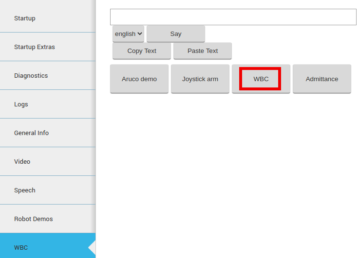
Figure: Start WBC
The second option is to change the controllers via rosservice call.
First connect to the robot through a terminal:
ssh pal@tiago-0c
Stop several controllers:
rosservice call /controller_manager/switch_controller "start_controllers:
- ''
stop_controllers:
- 'head_controller'
- 'arm_left_controller'
- 'arm_right_controller'
- 'torso_controller'
- 'whole_body_kinematic_controller'
strictness: 0"
Unload the current WBC:
rosservice call /controller_manager/unload_controller "{name:'whole_body_kinematic_controller'}"
And launch it:
roslaunch tiago_dual_wbc tiago_dual_wbc.launch
This starts WBC with the basic stack presented in the previous subsection.
If the user only wants to load the wbc controller just run:
roslaunch tiago_dual_wbc tiago_dual_wbc.launch spawn:=false
rosservice call /controller_manager/load_controller "name: 'whole_body_kinematic_controller'"
Once WBC is loaded the user could start it by executing on a terminal connected to the robot:
rosservice call /controller_manager/switch_controller "start_controllers:
- 'whole_body_kinematic_controller'
stop_controllers:
- ''
strictness: 0"
This last step won’t work if there are other controllers active that share resources such as arm_controller, torso_controller or head_controller.
Push tasks to the stack
To push new tasks to the stack there is a specific service to do it:
rosservice call /whole_body_kinematic_controller/push_task
"push_task_params:
  params: ''
  respect_task_id: ''
  order:
  order: 0
  blend: false"
Although it requires to define all the params of the task.
The easiest way to push a task to command a specific link to a desired pose, and another one to command the head of the robot to gaze a specific point is to run:
roslaunch tiago_dual_wbc push_reference_tasks.launch
source_data_arm:=topic_reflexx_typeII source_data_gaze:=topic
After those steps there will be five new tasks that:
Command the position of /arm_left_tool_link in cartesian space: to allow the end-effector to be sent to any spatial position.
Command the position of /arm_right_tool_link in cartesian space: to allow the end-effector to be sent to any spatial position.
Command the pose /xtion_optical_frame link in cartesian space: to allow the robot to look towards any direction.
Command the orientation of /arm_left_tool_link in cartesian space: to allow the end-effector to be sent to any spatial orientation.
Command the orientation of /arm_right_tool_link in cartesian space: to allow the end-effector to be sent to any spatial orientation.
There are now the following ROS topics:
/whole_body_kinematic_controller/arm_left_tool_link_goal (geometry_msgs/PoseStamped)
Topic to specify the goal pose of the arm left tool link.
/whole_body_kinematic_controller/arm_right_tool_link_goal (geometry_msgs/PoseStamped)
Topic to specify the goal pose of the arm right tool link.
/whole_body_kinematic_controller/gaze_objective_xtion_optical_frame_goal (geometry_msgs/PoseStamped)
Topic to specify the spatial point that the camera on the head has to look at.
Example to send a goal for the arm
A goal can be sent through command line, for instance, as follows:
Replace arm_tool_link_goal with arm_left_tool_link_goal or arm_right_tool_link_goal to move the left or right arm before executing these commands.
rostopic pub /whole_body_kinematic_controller/arm_tool_link_goal \geometry_msgs/PoseStamped "
header:
    seq: 0
    stamp:
        secs: 0
        nsecs: 0
    frame_id: '/base_footprint'
pose:
    position:
        x: 1.0
        y: 0.0
        z: 0.5
    orientation:
        x: 0.0
        y: 1.0
        z: 0.0
        w: 0.0"
When running this example you will notice how the WBC moves the torso and arm in order to set /arm_tool_link to
the desired pose, bringing the origin of this frame to the point (1,0,0.5) expressed in /base_footprint,
which is a point that lies 1 m in front of the robot and 0.5 m above the floor. Notice that the desired orientation of /arm_tool_link is also specified using a quaternion.
If the orientation or position sent to the robot is unreachable, the robot will try to go to the closest distance or orientation possible.
Example to send a goal for the head
A goal can be sent through command line as follows:
rostopic pub \/whole_body_kinematic_controller/gaze_objective_xtion_optical_frame_goal \geometry_msgs/PoseStamped "
header:
    seq: 0
    stamp:
        secs: 0
        nsecs: 0
    frame_id: '/base_footprint'
pose:
    position:
        x: 1.0
        y: 0.0
        z: 0.5
    orientation:
        x: 0.0
        y: 0.0
        z: 0.0
        w: 1.0"
With this goal, the robot’s head will move so that the camera looks towards the point at which the arm had been sent using the previous example.
Get the current stack
At any time that WBC is active it could be checked the current stack by calling:
rosservice call /whole_body_kinematic_controller/get_stack_description
It should appear a list with the tasks described before.
Remove a task from the stack
There is also the possibility to remove one of multiple tasks from the stack online. In a terminal connected from the robot run:
rosservice call /whole_body_kinematic_controller/pop_task
"name: 'orientation_arm_tool_link' blend: false"
The task to send the /arm_tool_link to a specific orientation will be removed.
It can be double checked by getting the current stack, or by trying to send the arm to a specific position with a specific orientation. The user will notice that the robot goes to the desired position with the orientation choosen by the optimizer.
Is very important to take care when removing the tasks. The tasks self_collision and joint_limits should be never removed since it could damage the robot.
Stopping the WBC
To stop WBC, open a browser with the web commander and push the Default controllers button located at the Commands section (see figure below)
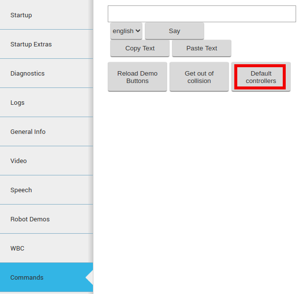
Figure: Stop WBC
This will automatically stop WBC and start the head, torso and arm controllers.
The second option is to change the controllers via rosservice call using a terminal.
Connect to the robot through a terminal and switch the controllers:
rosservice call /controller_manager/switch_controller "start_controllers:
- 'head_controller'
- 'arm_controller'
- 'torso_controller'
stop_controllers:
- 'whole_body_kinematic_controller'
strictness: 0"
40.3 WBC with Aruco demo
In this demo the robot upper body will be controlled by the WBC default stack of tasks so that both the head and the end-effector of the arm will point to an Aruco marker when shown to the robot.
A video featuring such a demo can be found in https://youtu.be/kdwShb-YrbA. See some snapshots of the demo in figure below:
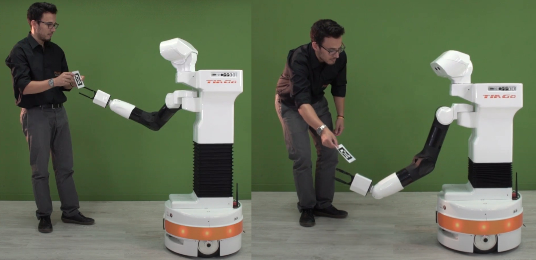
Figure: Aruco demo using WBC in action
In order to start the demo make sure that the head_manager node is running by checking it in WebCommander Startup section and then go to section WBC and press the Aruco demo button as shown in figure below:
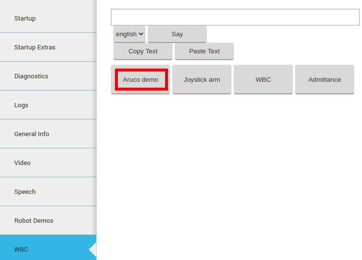
Figure: Start the Aruco demo with WBC
The robot will raise its arm and when ready will start detecting the Aruco marker specified in figure below. The
position controllers will bet stopped and the Whole Body Controller will be started automatically.
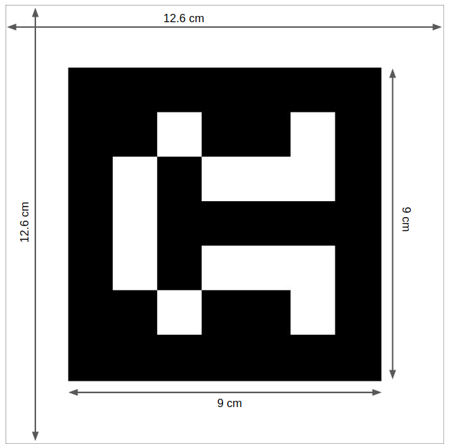
Figure: Aruco marker with code 582 and proper dimensions and white margin
In order to stop the demo press the same button that now reads CANCEL Aruco demo.
This button also stops the Whole Body Controller and restores the default position controllers.
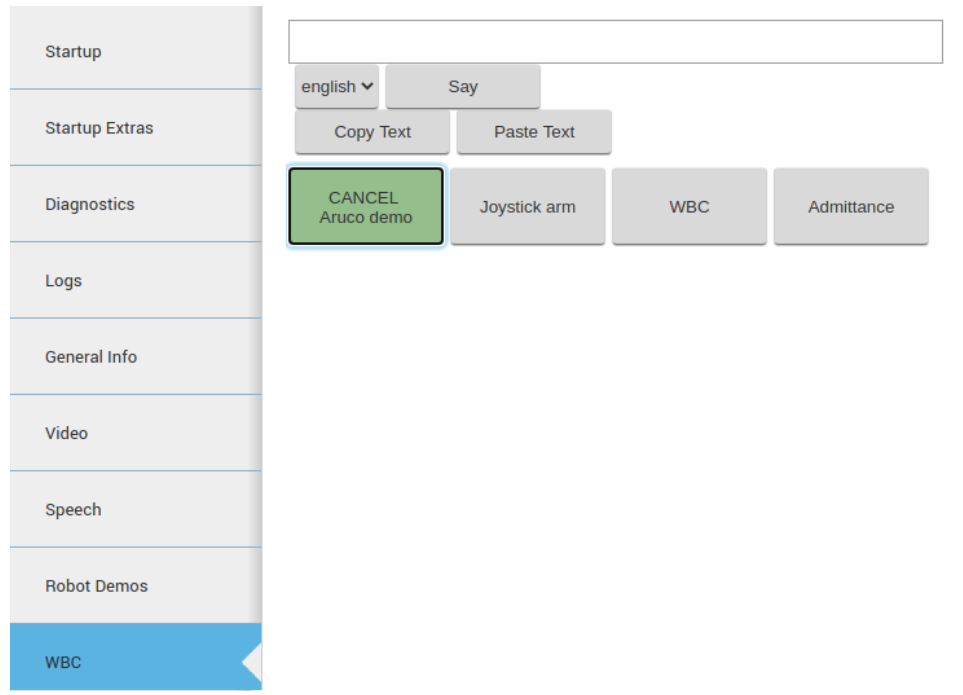
Figure: Stop the Aruco demo with WBC
40.4 WBC upper-body teleoperation with joystick
WBC provides a simple way to command the end-effector pose using the joystick. The torso lift and arm joints
will be automatically controlled in order to move and rotate the end-effector in cartesian space. In order to start
it, open the WebCommander from your browser and press the the Joystick arm button in WBC Demos section. (see figure below)
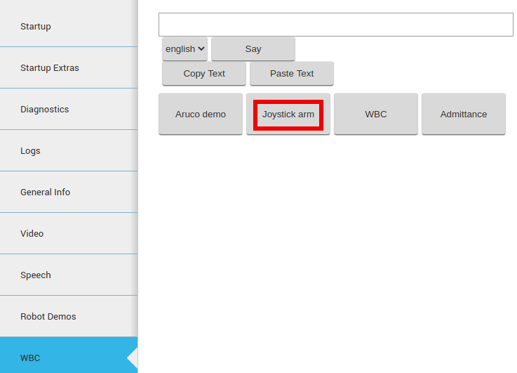
Figure: Start teleoperation with joystick
A video showing this demo can be found in https://youtu.be/kdwShb-YrbA starting at second 32.
The robot’s arm will extend, and the operator will then be able to use the joystick to command the pose. In
order to teleoperate, the user has to gain the joystick priority by pressing the button START, as shown in
figure below. Note that pressing this button will give the operator control of the mobile base and the upper body
alternatively. Press it once or twice until the mobile base is no longer controlled with the joystick.
Figure: Button to gain control of the arm
The user can control the position of the end-effector with respect to the base_footprint frame, which lies at the center of the robot’s mobile base, as shown in figure below:
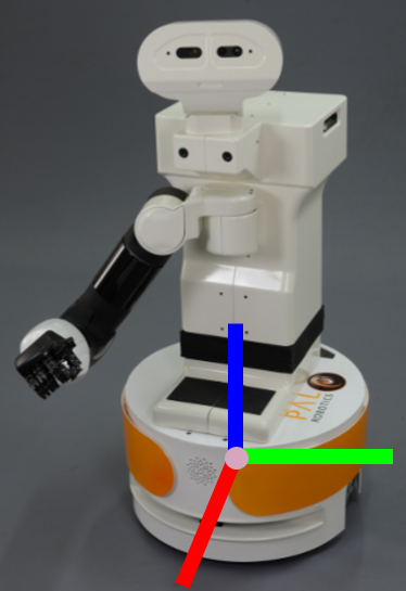
Figure: Button to gain control of the arm
The following motions can be controlled with the joystick:
To move the end-effector along the
Xaxis of the reference frame: press the left analog stick as shown in the first figure below a. Pressing upwards will move the end-effector forward; pressing downwards will move the end-effector backward.To move the end-effector along the
Yaxis of the reference frame: press the left analog stick as shown in the first figure below b. By pushing this stick left or right, the end-effector will move laterally in the same direction.To move the end-effector along the
Zaxis of the reference frame: press the right analog stick as shown in the first figure below c. Pressing upwards will move the end-effector upwards; pressing downwards will move the end-effector downwards.To rotate the end-effector along the
Yaxis of the reference frame: press the left pad as shown in the second figure, Figure: Buttons to rotate the end-effector in cartesian spac aTo rotate the end-effector along the
Zaxis of the reference frame: press the left pad as shown in the second figure bTo rotate the end-effector along the
Yaxis of the reference frame: press theLBandLTbuttons from thejoystick as shown in the second figure cTo go back to the initial pose press the
BACKbutton from the joystick. as shown in Figure: Button to go back to the initial position
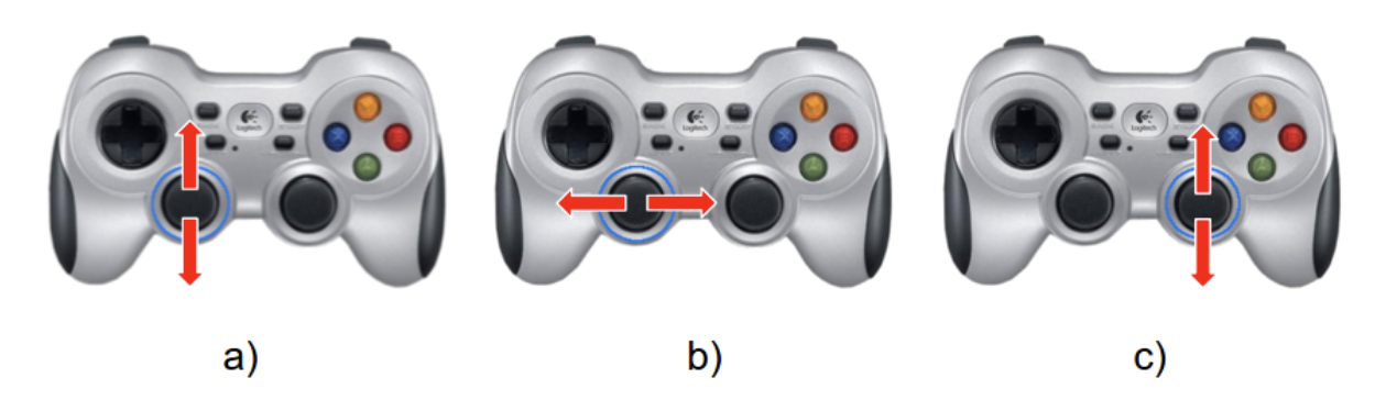
Figure: Buttons to move the end-effector in cartesian space
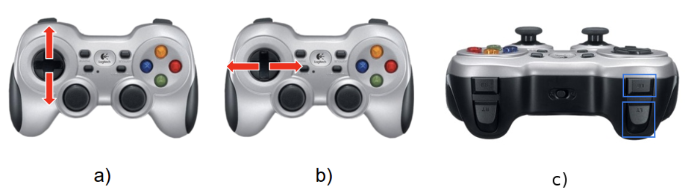
Figure: Buttons to rotate the end-effector in cartesian space
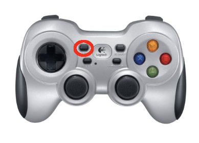
Figure: Button to go back to the initial position
In order to stop the demo click on the same button which now should appear in blue. This will automatically stop WBC and will restore the default controllers.
40.5 WBC with admittance control demo
In this demo the Whole Body Controller including admittance control is started and demonstrated. This demo is only available if the robot has Force/Torque sensor on the wrist.
In order to start the demo press the Admittance button in the WBC section of the WebCommander as shownin figure below:
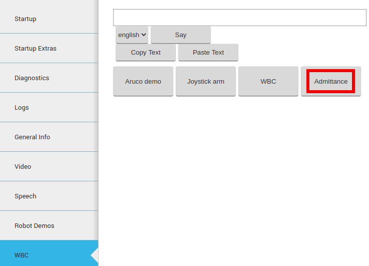
Figure: Admittance demo using WBC
When ready, the robot will start drawing an ellipse in the space with the tip of its end-effector. As the admittance controller is running, the user can exert forces on the end-effector to perturbate the trajectory of the arm. When the perturbation is removed, the robot will automatically go back to its orginal trajectory.
In order to stop the demo press the same button that now reads CANCEL Admittance.
40.6 WBC upper-body teleoperation with leap motion
Using WBC, the robot can be teleoperated with a leap motion camera, as soon as the robot boots up. This leap motion camera tracks the position and orientation of the hand, as well as the different hands gestures. The user could rotate, move and control the end effector of the robot as his own hand.
A video showing this demo can be found in https://youtu.be/kdwShb-YrbA starting at second 76.
In order to execute the demo, it is necessary to use a development computer to connect the leap motion camera and run the software that will send teleoperation commands to the robot. First of all, in order to ensure that the ROS communication works properly between the robot and the development computer, it is necessary to set up the development computer hostname and IP address in the robot’s local DNS, as explainedin section 12.4 ROS communication with the robot
Then, in the development computer, open a terminal and execute the following commands:
Enter as a superuser:
sudo su
Enter your sudoer password and then execute:
export ROS_MASTER_URI=http://tiago-0c:11311
export ROS_IP=10.68.0.128
source /opt/LeapSDK/leap_setup.bash
roslaunch leap_motion_demo leap_motion_demo.launch
Make sure to use your robot’s serial number when exporting the ROS_MASTER_URI variable and to set yourdevelopment computer’s IP when exporting ROS_IP as explained in section 12.4 ROS communication with the robot.
Wait until the robot moves to the initial pose shown in Figure: a) Robot initial pose of wbc teleoperation demo, and until the terminal in the development computer shows the following messages:
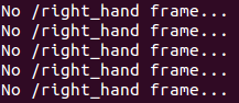
At this point, the user can place his/her open hand above the leap motion camera, as shown in Figure: b) Operator hand pose The terminal will start printing messages like the following:
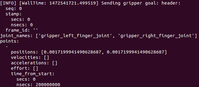
These messages appear when the user’s hand is properly tracked and teleoperation commands are being sent to the robot’s WBC. You should see the robot’s arm, torso and end-effector moving according to the user’s hand movements. The leap motion camera is able to track the human hand at several heights, closed and open. The leap motion tracking works best when the hand is kept as flat as possible.
If the leap motion sensor is not tracking the hand, please make sure that the leap motion is connected, and that a red light is lit in the center as shown in figure below:
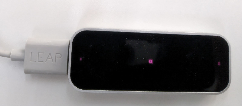
Figure: Leap motion sensor started
If the light is not on, or the robot didn’t move to the WBC default reference, close the previous terminal and restart the process. This issue is being adressed by PAL and should be fixed in future versions.
Once finished, to stop the demo, press CTRL+C in the terminal. The robot will then move back to the initial pose.
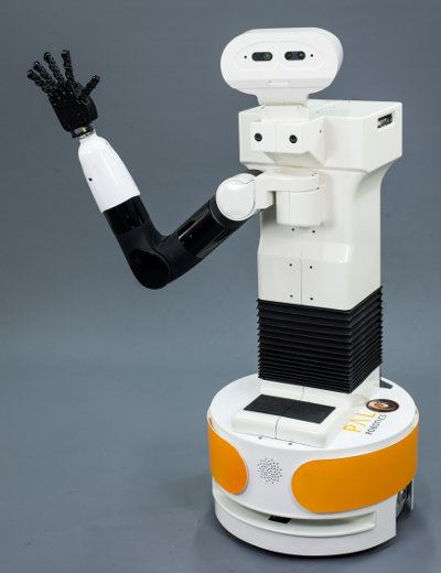
Figure: a) Robot initial pose of wbc teleoperation demo
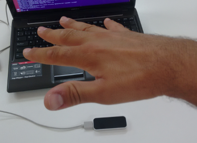
Figure: b) Operator hand pose
As the robot won’t change automatically from whole_body_kinematic_controller to position controllers
when stopping the demo. It will be necessary to change the control mode back to position control, by pressing
the Default controllers button in Demos of the WebCommander, as explained before.
40.7 WBC with rviz interactive markers
An easy way to test the WBC’s capabilities is by using rviz and moving the robot’s head and arm by moving interactive markers.
Open a terminal from the development computer and connect to the robot:
Make sure there are no obstacles in front of the robot, as the arm will extend when the WBC is launched.
Launch WBC as stated in Starting the WBC. The easiest way is to launch it from WebCommander.
Then open a new terminal connected to the robot and push the necessary tasks into the stack.
ssh pal@tiago-0c
roslaunch tiago_wbc push_reference_tasks.launch
Open a new terminal in the development computer and run rviz as follows:
source /opt/pal/${PAL_DISTRO}/setup.bash
export ROS_MASTER_URI=http://tiago-0c:11311
export ROS_IP=10.68.0.128
rosrun rviz rviz -d `rospack find tiago_wbc`/config/rviz/tiago_wbc.rviz
Make sure to use your robot’s serial number when exporting the ROS_MASTER_URI variable and to set your development computer’s IP when exporting ROS_IP as explained in section 12.4 ROS communication with the robot
Rviz will show up, as in the figure below, and the user will be able to command the robot’s head and end-effector by dragging and rotating the two interactive markers that will appear.
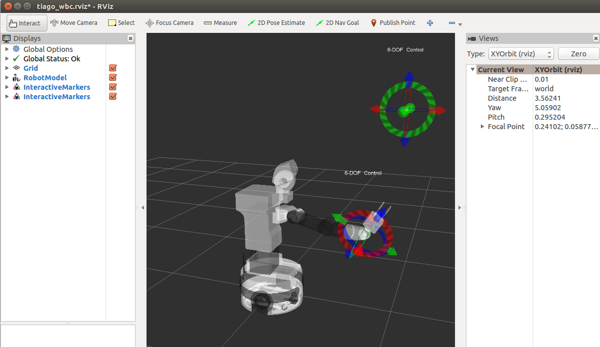
Figure: WBC demo with rviz
In order to stop the demo, close rviz by pressing CTRL+C, and start the default controllers as explained in Stopping the WBC subsection.
41 Change controllers
In order to change robot controllers, as for example to start whole body kinematic controller or gravity compensation controller, and stop position controllers there are two ways to do it.
1- Use the rosservice API with the controller manager services
2- Use the change controllers action
41.1 Controller manager services
There are three main services.
List controllers It lists all the loaded controllers, and shows wich of them are active (running) and which of them are unactive (stopped).
ssh pal@tiago-0c
rosservice call /controller_manager/list_controllers
Also lists the resources used for every controller.
It is important to remark that ROS control doesn’t allow two active controllers using a common resorce.
Load controllers It loads a controller. The parameters for the specific controller must be loaded previously on the param server.
ssh pal@tiago-0c
rosservice call /controller_manager/load_controller "name:
  'controller_name'"
It returns true if the controller has been loaded correctly, and false otherwise.
Switch controllers Starts and/or stops a set of controllers. In order to stop a controller this should be active. A controller must be loaded before start it.
ssh pal@tiago-0c
rosservice call /controller_manager/switch_controller "start_controllers:
- 'whole_body_kinematic_controller'
stop_controllers:
- 'head_controller'
- 'arm_controller'
- 'torso_controller'
strictness: 0"
It is recommended to start and stop the desired controllers in one service call.
In the case of the gravity_compensation_controller this is crucial, because once the controller is stopped, the current applied on the arm is zero so it falls down.
The service returns true if the switch has been successfully executed, false otherwise.
Unload controllers It unloads a controller. The controller must be stopped before being unload.
ssh pal@tiago-0c
rosservice call /controller_manager/unload_controller "name:
  'controller_name'"
It returns true if the controller has been unloaded correctly, and false otherwise.
Once a controller has been unloaded, in order to restart it, it will be necessary to load it again.
41.2 Change controllers action
The change controllers action uses the rosservice API of the controller manager, but allows the change of controllers in a simple and intuitive way in a single call. The user doesn’t need to know which controllers are active and which resources are being used at any time. The action automatically stops the active controllers that share resources with those who want to be loaded. Moreover it has different flags in the goal msg:
switch_controllers: If true it stops and starts the controller in a single switch service call. Otherwise, first it calls stop and then it calls start. By default this should be always True. Specially when gravity_compensation_controller needs to be stopped.
load: Load the controller that is gonna be started.
unload: Unload the request stop controllers. This doesn’t affect the controllers that are automatically stopped becasue they share resources with the controllers that are gonna be started.
This action is also optimized to avoid issues with PAL controllers, as for example the whole body kinematic controller needs to be unloaded and loaded every time.
export ROS_MASTER_URI=http://tiago-0c:11311
# For ROS Melodic
rosrun actionlib axclient.py /change_controllers

# For ROS Noetic
rosrun actionlib_tools axclient.py /change_controllers
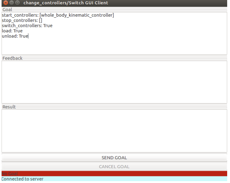
Change controllers action
In the robot the server is automatically launched on the startup. To run it on simulation execute.
roslaunch change_controllers change_controllers.launch
42 Introspection controller
The introspection controller is a tool used at PAL to serialize and publish data on the real robot that could be recorded and used later for debugging.
42.1 Start the controller
The introspection controller doesn’t use any resource, and it could be activated in parallel with any other controller.
In order to start it run:
ssh pal@tiago-0c
roslaunch introspection_controller introspection_controller.launch
Once the controller is started it will start publishing all the information on the topic: /introspection_data/full
42.2 Record and reproduce the data
If you want to record the information from your experiment, it can simply be done using rosbag.
ssh pal@tiago-0c
rosbag record -O NAME_OF_THE_BAG /introspection_data/full
Once you are finished to record your experiment simply close it with Ctrl-C
Then copy this file in your development PC
ssh pal@tiago-0c
scp -C NAME_OF_THE_BAG.bag pal@development:PATH_TO_SAVE_IT
Once in your development PC you can reproduce it using PlotJuggler.
rosrun plotjuggler PlotJuggler
Once PlotJuggler is open load the bag: File -> Load Data and select the recorded rosbag.
For more information about PlotJuggler please visit: http://wiki.ros.org/plotjuggler
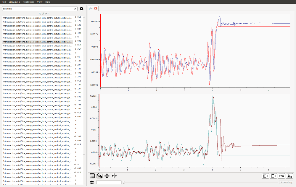
PlotJuggler
42.3 Record new variables
In order to record new variables it will be necessary to register them inside your code as follows.
#include <pal_statistics/pal_statistics.h>
#include <pal_statistics/pal_statistics_macros.h>
#include <pal_statistics/registration_utils.h>
...
double aux = 0;
pal_statistics::RegistrationsRAII registered_variables_;
REGISTER_VARIABLE("/introspection_data", "example_aux", &aux, ®istered_variables_);
Eigen::Vector3d vec(0,0,0);
REGISTER_VARIABLE("/introspection_data", "example_vec_x", &vec[0], ®istered_variables_);
REGISTER_VARIABLE("/introspection_data", "example_vec_y", &vec[1], ®istered_variables_);
REGISTER_VARIABLE("/introspection_data", "example_vec_z", &vec[2], ®istered_variables_);
...
Take in account that the introspection controller only accepts one dimensional variables. For more information please check: https://github.com/pal-robotics/pal_statistics
43 Simulation
43.1 Overview
When installing a development computer, as explained in 10.3 Development computer installation, the user can run Gazebo simulations of TIAGo++.
Three different simulation worlds are provided with TIAGo++, which are described in the following subsections.
43.1.1 Empty world
This is the default world that is loaded when the simulation is launched. The robot is spawned in an empty world with no objects, as shown in Figure: Empty world simulated in Gazebo. In order to launch the simulation, the following instruction needs to be executed in a terminal:
source /opt/pal/${PAL_DISTRO}/setup.bash
roslaunch tiago_0_gazebo tiago_gazebo.launch
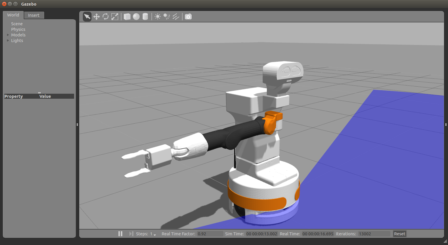
Figure: Empty world simulated in Gazebo
43.1.2 Office world
The simple office world shown in Figure: Small office world simulated in Gazebo can be simulated with the following instruction:
source /opt/pal/${PAL_DISTRO}/setup.bash
roslaunch tiago_0_gazebo tiago_gazebo.launch world:=small_office
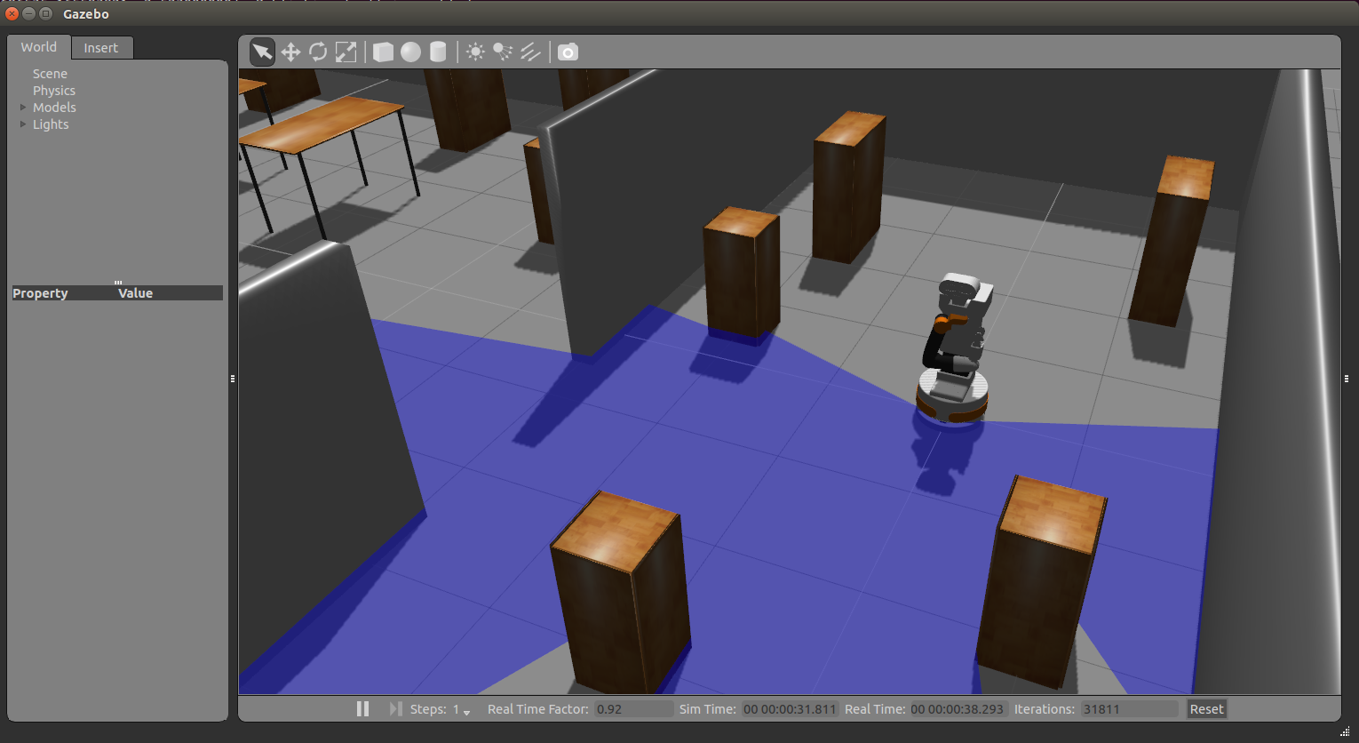
Figure: Small office world simulated in Gazebo
43.1.3 Table with objects world
In this simulation, TIAGo++ is spawned in front of a table with several objects on top, see Figure: Tabletop scenario simulation. The instruction needed is:
source /opt/pal/${PAL_DISTRO}/setup.bash
roslaunch tiago_0_gazebo tiago_gazebo.launch world:=objects_on_table
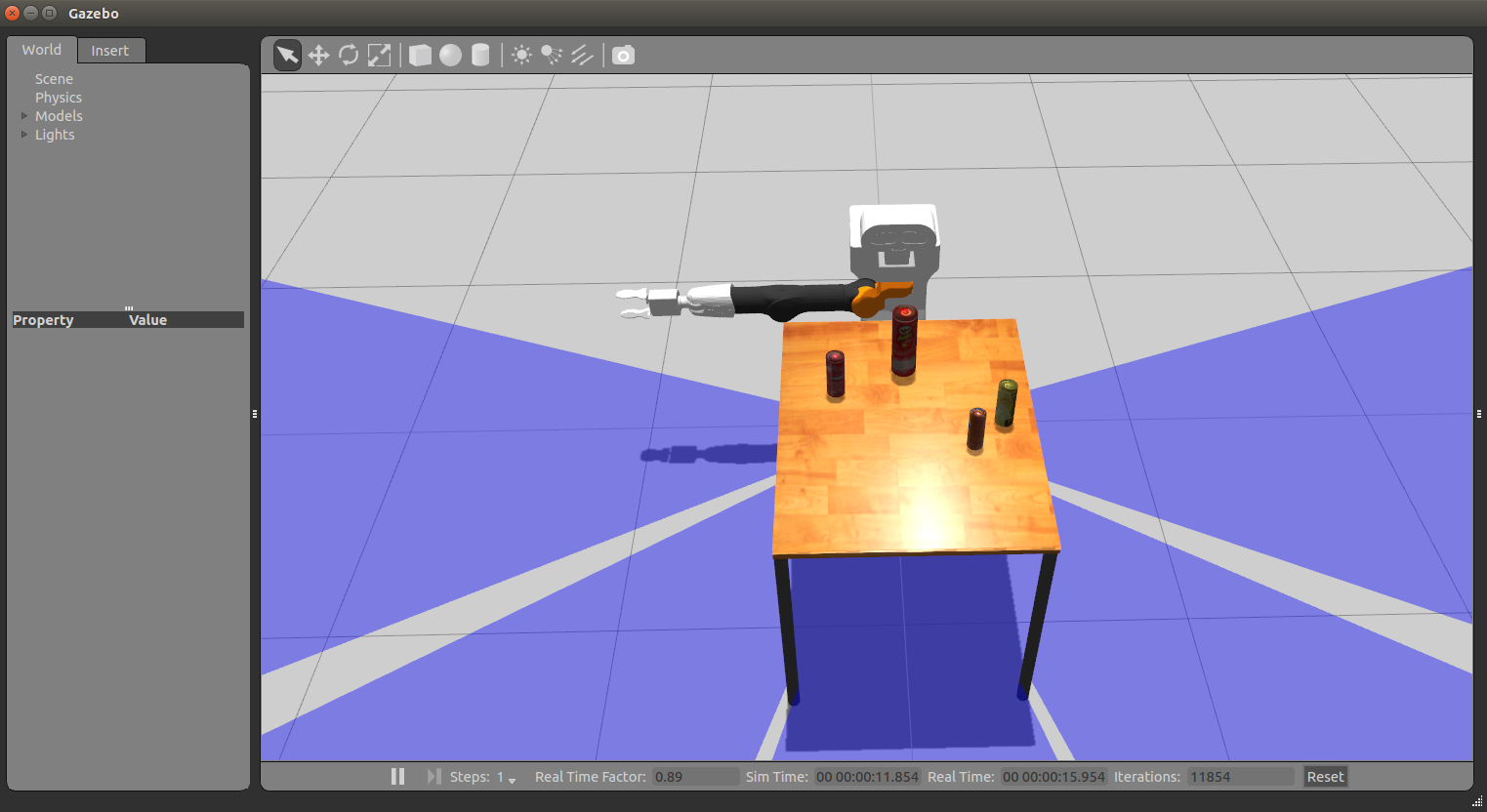
Figure: Tabletop scenario simulation
44 LEDs
This section contains an overview of the LEDs included in TIAGo++.
44.1 ROS API
Note
The services provided for controlling the LEDs are launched by default on startup.
Keep in mind that there is an application running in TIAGo++ that changes the LED strips according to the robot’s
speed. This application must be stopped if any operation with the LED strips is to be performed. It can be
done by calling the pal-stop script as follows.
pal@tiago-0c:~$ pal-stop pal_led_manager
result: pal_led_manager stopped successfully
44.1.1 Available services
The following services are used for controlling the LED strips present in TIAGo++. All require a port argument that specifies which strip the command will affect. A port of value 0 referes to the left strip and 1 to the right strip. LED strips are composed of pixel LEDs.
Note
Resulting color may be different or not visible at all due to the plastic that covers the LED strips.
/mm11/led/set_strip_color port r g b
Sets all the pixels in the strip to a color. r,g and b refers to the color to be set in RGB scale.
pal@tiago-0c:~$ rosservice call /mm11/led/set_strip_color 0 255 255 255
/mm11/led/set_strip_pixel_color port pixel r g b
Sets one pixel in the strip to a color. pixel is the position of the LED in the strip. r, g and b refers to the color to be set in RGB scale.
pal@tiago-0c:~$ rosservice call /mm11/led/set_strip_pixel_color 0 5 255 0 0
/mm11/led/set_strip_flash port time period r_1 g_1 b_1 r_2 g_2 b_2
Sets a flashing effect to the LED strip. time is the duration of the flash in milliseconds. period is the time between flashes in milliseconds. r_1, g_1 and b_1 refers to the color of the flash in RGB scale. r_2, g_2 and b_2 refers to the background color of the flash in RGB scale.
pal@tiago-0c:~$ rosservice call /mm11/led/set_strip_flash \
0 100 1000 255 0 0 0 0 255
/mm11/led/set_strip_animation port animation_id
param_1 param_2 r_1 g_1 b_1 r_2 g_2 b_2
Sets an animation effect to the LED strip. animation_id sets the type of animation: 1 for pixels running left, 2 for pixels running right,3 for pixels running back and forth starting from the left, and 4 for pixels running back and forth starting from the right. param_1 is the time between effects in milliseconds. param_2 is the distance between animated pixels. r_1, g_1 and b_1 refers to the color of the animation in RGB scale. r_2, g_2 and b_2 refers to the background color of the animation in RGB scale.
pal@tiago-0c:~$ rosservice call /mm11/led/set_strip_animation \ 0 1 100 5 250 0 0 0 0 255
45 Modifying the base touch screen
This section describes how the menu of the robot’s base touch screen is implemented and how to modify it.
45.1 Introduction
TIAGo++ touch screen is configured via YAML files that are loaded as ROS Parameters upon robot startup.
The menu can display labels and buttons, and the buttons can be pressed to navigate to another menu, or to execute a command.
The application will look for a directory in $HOME/.pal/touch_display_manager_cfg, if it does not exist it will load the configuration in the touch_display_manager_cfg ROS package’s config directory.
45.2 Configuration file structure
Below is an example configuration file
main_menu:
    type: ConfigurableMenu
    params:
      - text: "Example menu"
        entry_type: Label
      - text: "Mute"
        entry_type: ActionButton
        action:
          remote_shell:
            cmd: "rosparam set /pal/playback_volume 0"
            target: "control"
      - text: "Unmute"
        entry_type: ActionButton
        action:
          remote_shell:
            cmd: "rosparam set /pal/playback_volume 85"
            target: "control"
At the root of the file, there are the different menus, there must exist at least one menu with the name main_menu, this is the menu loaded by default.
Each menu must specify its type, as well as parameters (params) that depend on it’s type.
46 Tutorials
A comprehensive set of tutorials are provided in the public ROS wiki of TIAGo++ in http://wiki.ros.org/Robots/TIAGo/Tutorials. The source code is hosted in PAL Robotics’ github public repositories, under https://github.com/pal-robotics/tiago_dual_tutorials.
46.1 Installing pre-requisites
The following ROS package needs to be installed in the development computer:
sudo apt-get install ros-melodic-humanoid-nav-msgs ros-melodic-moveit-commander
46.2 Downloading source code
First of all, create an empty workspace in a development computer:
mkdir ~/tiago_public_ws
cd ~/tiago_public_ws
mkdir src
cd src
Then clone the following repositories:
git clone https://github.com/pal-robotics/pal_msgs.git
git clone https://github.com/pal-robotics/aruco_ros.git
git clone https://github.com/pal-robotics/tiago_dual_tutorials.git
46.3 Building the workspace
In order to build the workspace, do the following:
cd ~/tiago_public_ws
source /opt/pal/${PAL_DISTRO}/setup.bash
catkin build
46.4 Running the tutorials
In order to run the different tutorials, refer to http://wiki.ros.org/Robots/TIAGo%2B%2B/Tutorials and skip the first section referring to Tutorials Installation.
The tutorials in the ROS wiki are intended to be run with the public simulation model of TIAGo++. In order to run them for your customized robot model, take into consideration to following:
- When running the tutorials in simulation the following arguments, which are stated in the ROS wiki, have to be removed in order to use your custom TIAGo version:
public_sim:=true
robot:=steel
robot:=titanium
Also, tiago_dual_0_gazebo must be used instead of tiago_dual_gazebo or tiago_dual_2dnav_gazebo. For example, when it suggests the operator runs the simulation like this:
roslaunch tiago_dual_gazebo tiago_dual_gazebo.launch public_sim:=true robot:=steel
Run the following command instead:
roslaunch tiago_dual_0_gazebo tiago_dual_gazebo.launch
When running the tutorials against the actual robot, run them from the development computer with the
ROS_MASTER_URIpointing to the robot computer, i.e.:
export ROS_MASTER_URI=http://tiago-0c:11311
export ROS_IP=10.68.0.128
Make sure to use your robot’s serial number when exporting the ROS_MASTER_URI variable and to set your development computer’s IP when exporting ROS_IP as explained in section 12.4 ROS communication with the robot.
The tutorials cover different ares, including control and motion generation, autonomous navigation, motion planning and grasping, and perception with OpenCV and PCL.
47 NVIDIA Jetson TX2
47.1 Overview
The NVIDIA Jetson TX2 add-on [10] is a dedicated AI computing device developed by NVIDIA that can be integrated into TIAGo++.
The TX2 provided with TIAGo++ is installed by PAL Robotics with an arm64 Ubuntu 18.04 (Jetpack 4.6 + cuda 10.2).
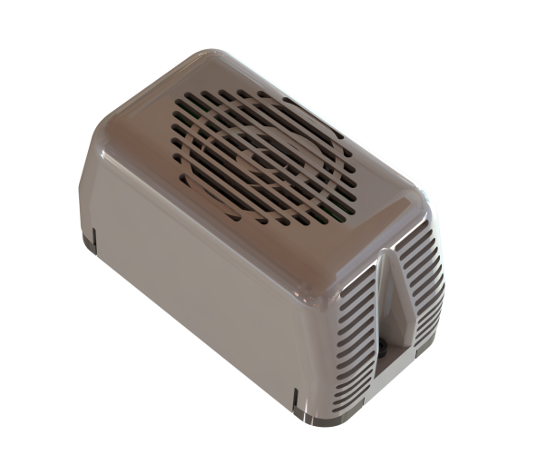
Figure: PAL Jetson add-on
47.2 Installation
The add-on device is meant to be attached to the back of TIAGo++ and connected to the expansion panel of the robot as shown in the figure below:
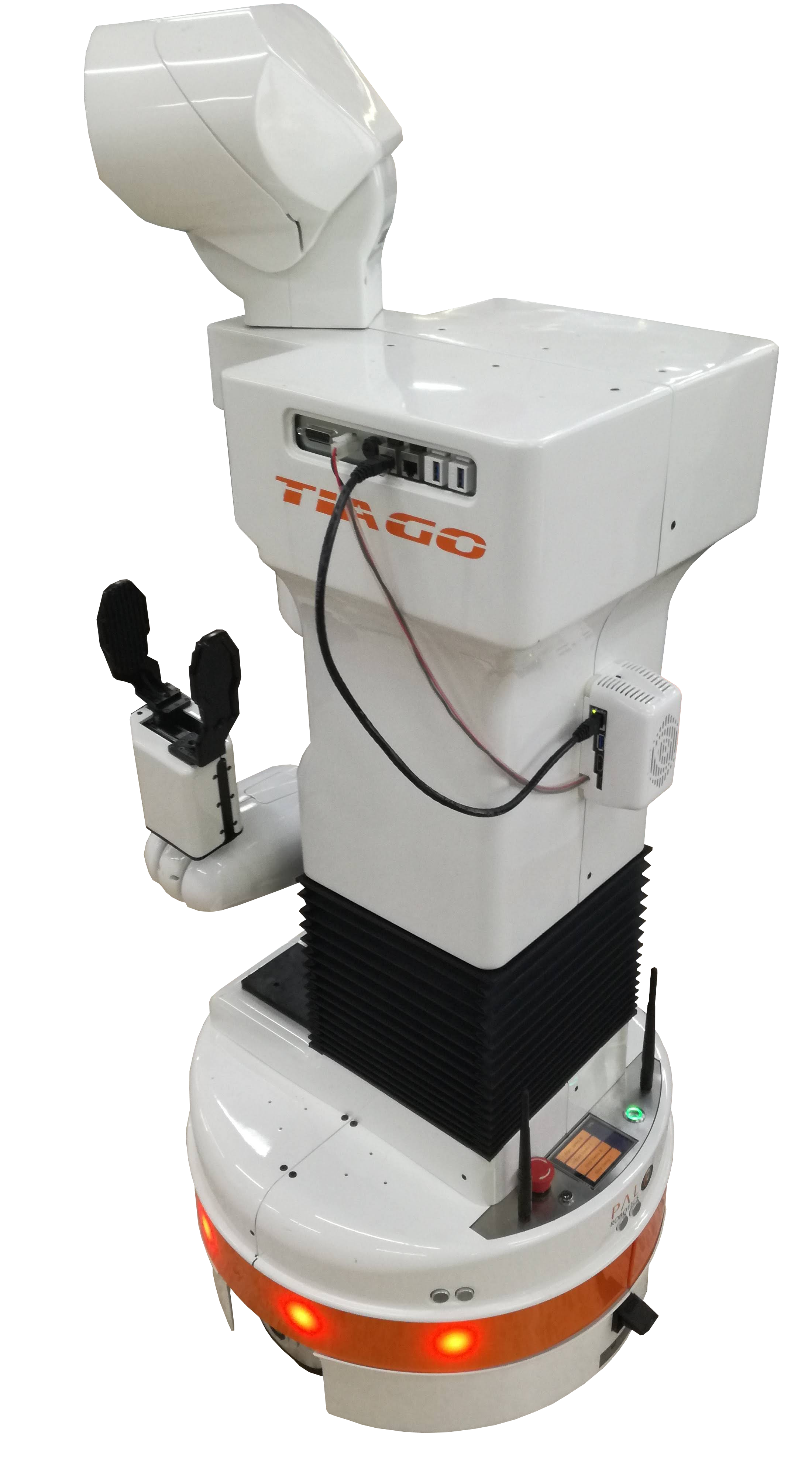
Figure: PAL Jetson add-on attached to TIAGo++
In order to attach the add-on the following components are provided:
NVIDIA Jetson TX2 encapsulated and with power supply cable, see figure below a.
Ethernet cable to connect the device to the expansion panel, see figure b.
Specific fasteners DIN 912 M3x18 to attach the device to the back of the robot, see figure c.
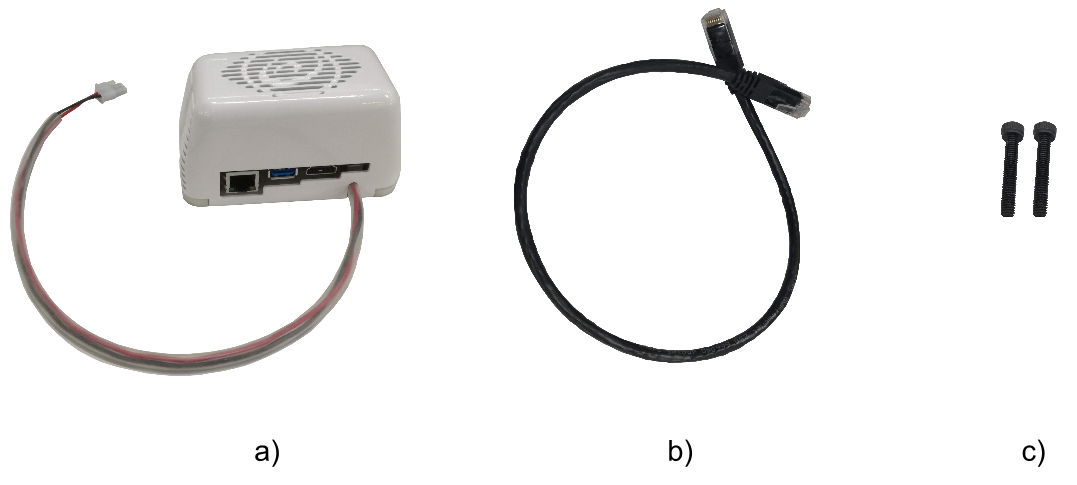
Figure: NVIDIA Jetson TX2 add-on contents
The installation steps are as follows:
Remove the two fasteners of the covers of the back of TIAGo++ as shown in Figure: Steps to install the add-on a.
Use the DIN 912 M3x18 provided fasteners to attach the add-on using the holes of the previous fasteners, see Figure: Steps to install the add-on b.
Connect the power supply cable of the add-on to the power source connector of the expansion panel and use the ethernet cable provided to connect the device to one of the GigE ports of the expansion panel, see Figure: Steps to install the add-on c.
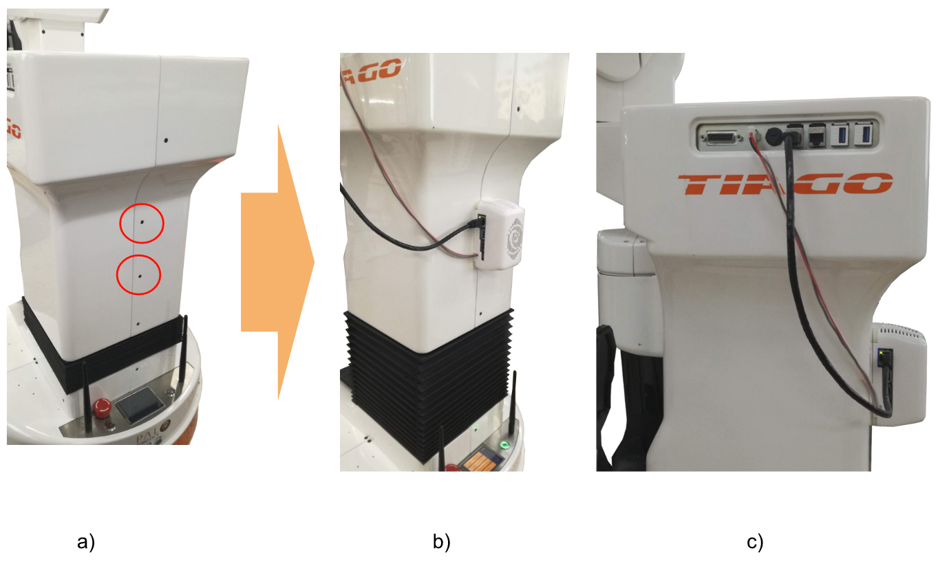
Figure: Steps to install the add-on
47.3 Connection
To access the TX2, the user must log into the robot’s control computer and then connect to the TX2 using its hostname tiago-0j:
ssh pal@tiago-0c
ssh pal@tiago-0j // or ssh jetson
47.4 Object detection API
We have provided an example that wraps the Tensorflow Object Detection with a ROS action server.
https://github.com/pal-robotics/inference_server
With TIAGo++, the example is provided inside a Docker image installed on the TX2, which isolates it from the potential changes to the installed libraries.
It is started automatically when the TX2 boots, and it can be used following the documentation on the example’s repository.
Keep in mind that the TX2 is not accessible from outside the control pc. So all applications that interact with it need to be run inside tiago-0c or relays it through topic_tools packages as shown in the below examples.
47.4.1 Inference parameters
Parameters are available to adapt the inference detections:
/inference_server/camera_topic
/inference_server/desired_classes
/inference_server/model_database_path
/inference_server/model_name
/inference_server/pub_topic
/inference_server/sub_topic
/inference_server/tf_models_path
And also services:
/inference_server/change_inference_model
/inference_server/get_loggers
/inference_server/set_logger_level
By default the /inference_server/model_name that is downloaded is ssd_inception_v2_coco_2018_01_28, this can be changed by other available models in the Tensorflow Zoo page depending on the requirements of performance needed:
rosservice call /inference_server/change_inference_model "model_name: 'ssd_mobilenet_v2_coco_2018_03_29'
reset_desired_classes_param: false"
It will take a few minutes to download and switch to the new model, after the service finishes the examples below can be launched with the new model
Keep in mind that the space on the Jetson TX2 is limited therefore not all packages can be installed successfully
By default, the inference server will try to detect every class available in the model chosen. The /inference_server/desired_classes can be set to only detect specific class
rosparam set /inference_server/desired_classes ['person']
47.4.2 Inference stream
The Object and Person Detection example starts an action server that takes an empty goal to start a video stream of inferred images with the name /inference_stream
47.4.2.1 How to test the example (Webcommander)
Once this image is shown in the inference Video section the inference demo is ready to be launched
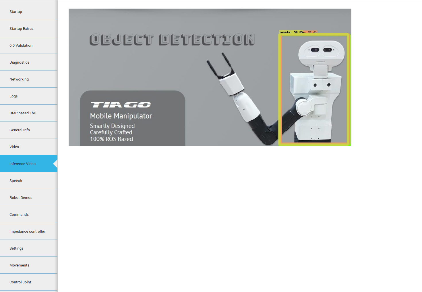
Figure: Inference Video tab in the Webcommander
The inference stream can be started in the Robot Demos tab by pressing the inference server button
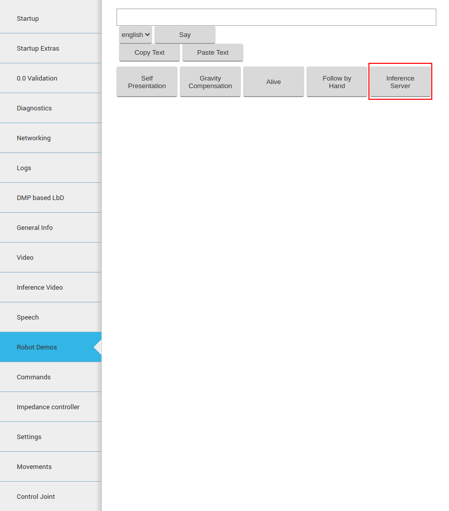
Figure: button to press to start the inference video
To stop the inference video, the inference server button needs to be pressed another time to cancel the action
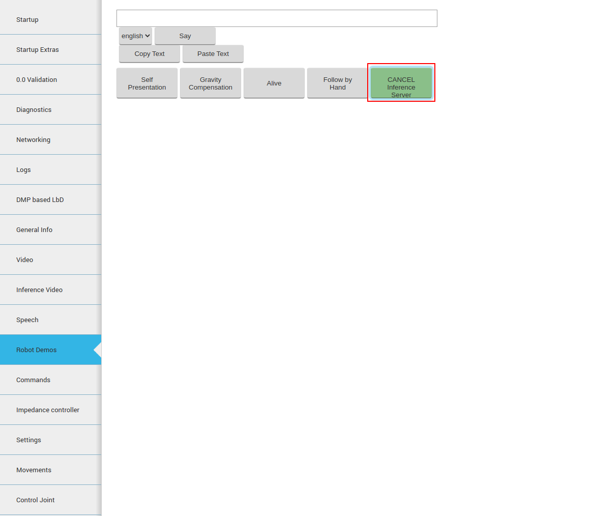
Figure: button to press to start the inference stream
47.4.2.2 How to test the example (Command line)
Through the command line, an empty goal can be sent to /inference_stream/goal to start the Inference Video:
rostopic pub /inference_stream/goal pal_common_msgs/EmptyActionGoal "header:
seq: 0
stamp:
    secs: 0
    nsecs: 0
frame_id: ''
goal_id:
stamp:
    secs: 0
    nsecs: 0
id: ''
goal: {}"
And to cancel:
rostopic pub /inference_stream/cancel actionlib_msgs/GoalID "stamp:
secs: 0
nsecs: 0
id: ''"
47.4.2.3 Output of the inference stream
The inference stream publishes a topic with the name /inference_detections and of type pal_detection_msgs/RecognizedObjectArray which has the following structure:
std_msgs/Header header
uint32 seq
time stamp
string frame_id
pal_detection_msgs/RecognizedObject[] objects
string object_class
float32 confidence
sensor_msgs/RegionOfInterest bounding_box
    uint32 x_offset
    uint32 y_offset
    uint32 height
    uint32 width
    bool do_rectify
To access this topic from outside the robot, this command needs to be run inside the robot:
rosrun topic_tools relay /inference_detections /inference_detections_relay
It will relay the /inference_detections topic to a new /inference_detections_relay topic accessible from outside the robot.
47.4.3 Single inference
The Object and Person Detection example also starts an action server with the name /inference_server and of type inference_server/InferenceAction which has the following structure:
sensor_msgs/CompressedImage input_image
---
sensor_msgs/CompressedImage image
int16 num_detections
string[] classes
float32[] scores
sensor_msgs/RegionOfInterest[] bounding_boxes
---
To run it, send a goal and the server will consider the input_image for the inference, if the input image is empty, then it captures an image from TIAGo++’s camera and returns the following fields, sorted by their score:
image Resultant image after inference from Object and Person Detection API
num_detections Number of detected objects in the inference image
classes Name of the class to which the object belongs (depends on the model used for the inference)
scores Detection scores or the confidence of the detection of the particular object as a particular class
- bounding_boxes Bounding box of each of the detected object
The node will also publish the /inference_image/image_raw image topic displaying the detections.
47.4.3.1 How to test the example
In order to test the Object detection action server provided the following instructions may be used in a development computer that can access the tiago-0c computer:
Open a terminal and run these instructions:
ssh pal@tiago-0c
rosrun topic_tools relay /inference_image/image_raw/compressed \ /jetson_detections/compressed
This command will take the image topic published by tiago-0j and republish it on the tiago-0c which is accessible from outside.
Open a second terminal and run an image_view node that will show the image with the detected objects:
export ROS_MASTER_URI=http://tiago-0c:11311
export ROS_IP=10.68.0.128
rosrun image_view image_view image:=/jetson_detections \ _image_transport:=compressed
Remember to assign the actual IP of the development computer to the ROS_IP on the instructions above.
On a third terminal run the following commands to enable object detection in the NVIDIA Jetson TX2:
export ROS_MASTER_URI=http://tiago-0c:11311
export ROS_IP=10.68.0.128

# For ROS Melodic
rosrun actionlib axclient.py /inference_server

# For ROS Noetic
rosrun actionlib_tools axclient.py /inference_server
when the GUI shows up, see figure below, press the SEND GOAL button.
After sending the action goal the image_view node started on the second terminal will refresh the image where the detected objects will be shown, see Figure: Object and person detection image example
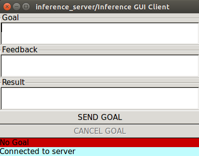
Figure: axclient GUI to send a goal to the object detector action server
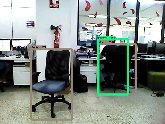
Figure: Object and person detection image example
48 Velodyne VLP-16
48.1 Overview
The Velodyne VLP-16 add-on [11] is a 3D LiDAR sensor with a range of 100 m. It supports 16 channels with ~300,000 points/second. VLP-16 has 360° horizontal field of view and 30° vertical field of view (±15° up and down). Velodyne VLP-16 LiDAR Puck sensor has been developed by Velodyne that can be integrated into TIAGo++.
Figure: Velodyne VLP-16 LiDAR add-on
48.2 Configuring Velodyne
The velodyne provided is configured with the IP 10.68.0.55. In order to access the velodyne configuration page, the connection with the development computer should be configured as following:
Configure the development computer’s IP address through the Gnome Interface
Access the Gnome Menu (Super key), type “Networks Connections” then run it. Select the connection’s name and click on “edit”. Choose the IPv4 Settings tab and change the “Method” field to “Manual” from the drop-down list.
Click on “add” and set the IP address field to
10.68.0.1(“1” can be any number in a range between 1 and 254, except 55). As the10.68.0.55address has already been taken by the sensor.Set the “Netmask” to
255.255.255.0and the “Gateway” to0.0.0.0.The settings should look similar as shown in the Figure: Velodyne network connection settings
To finalize the settings click on “Save”.
Accessing Velodyne Configuration
After finalizing the network configuration, power up the velodyne and connect it to the development computer. In the network connection, select the previously configured network configuration to establish the connection with the Velodyne sensor.
To check the configuration, open a web browser and access the sensor’s network address: 10.68.0.55.
The following page as shown in the Figure: Velodyne configuration page. The configuration of the sensor such as the firmware update,
Laser return type, Motor RPM, Field of View, Network settings etc. can be done in this page.
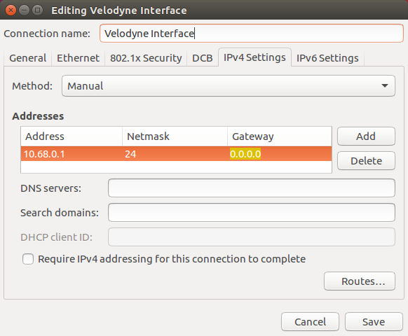
Figure: Velodyne network connection settings
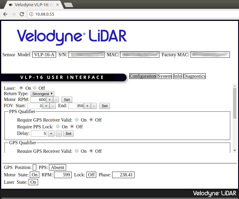
Figure: Velodyne configuration page
48.3 Installation
The add-on device is meant to be attached to the laptop tray of TIAGo++ and connected to the expansion panel of the robot as shown in the first figure below.
In order to attach the add-on the following components are provided:
Velodyne VLP-16 along with its mounting, see Figure: Velodyne VLP-16 kit contents a.
Ethernet cable and the power cable to connect the device to the expansion panel, see Figure: Velodyne VLP-16 kit contents b.
Specific fasteners DIN 912 M3x12 and washers DIN 9021 ø3 to attach the device to the back of the robot, see figure Figure: Velodyne VLP-16 kit contents c.
The installation steps are as follows:
Use the fasteners DIN 912 M3x12 and washers DIN 9021 ø3 provided to attach the add-on using the holes on the laptop tray of TIAGo++, see figure Figure: Steps to install the add-on.
Connect the power supply cable of the add-on to the power source connector of the expansion panel and use the ethernet cable provided to connect the device to one of the GigE ports of the expansion panel, see Figure: Steps to install the add-on.
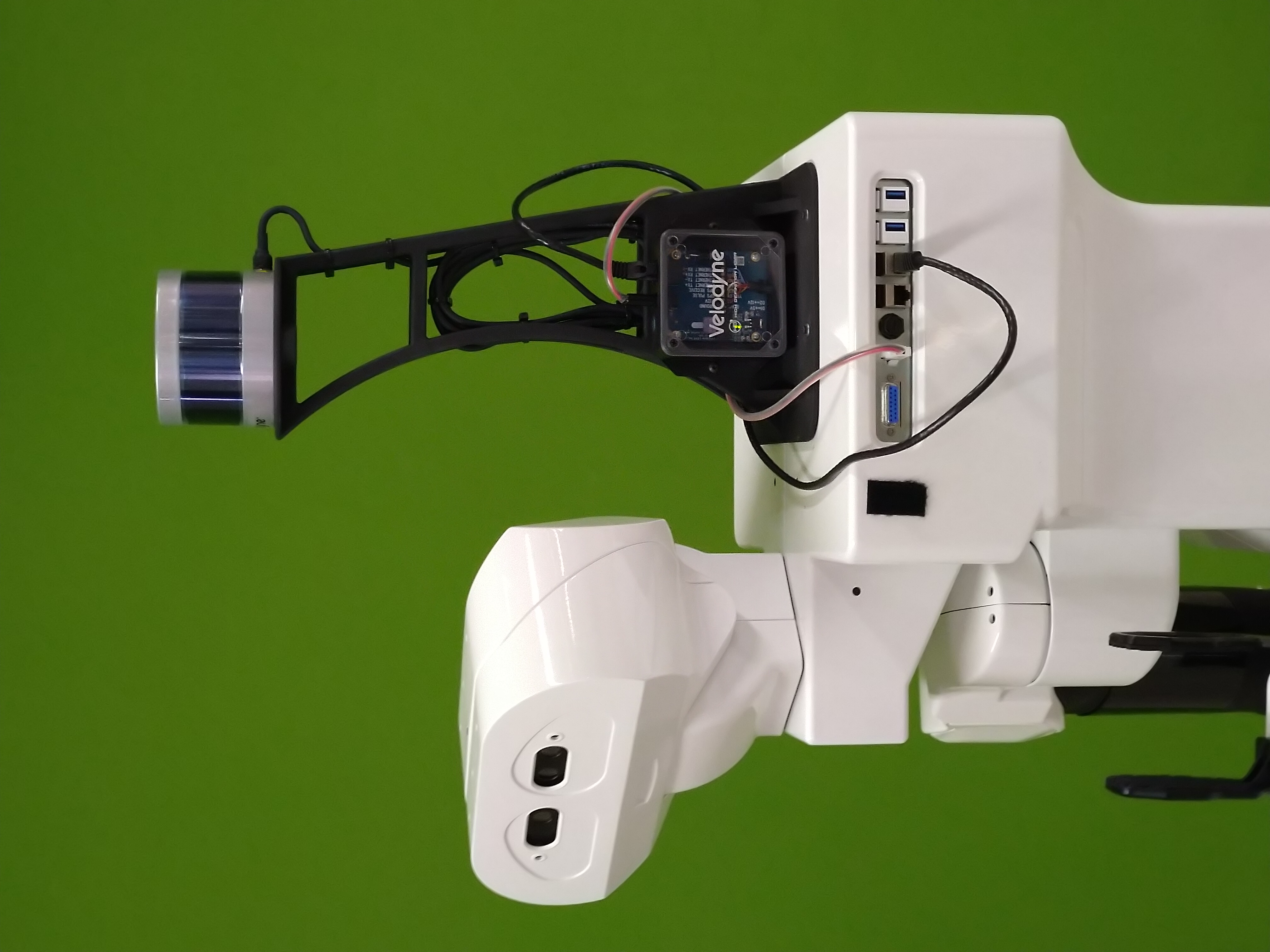
Figure: Velodyne VLP-16 add-on attached to TIAGo++
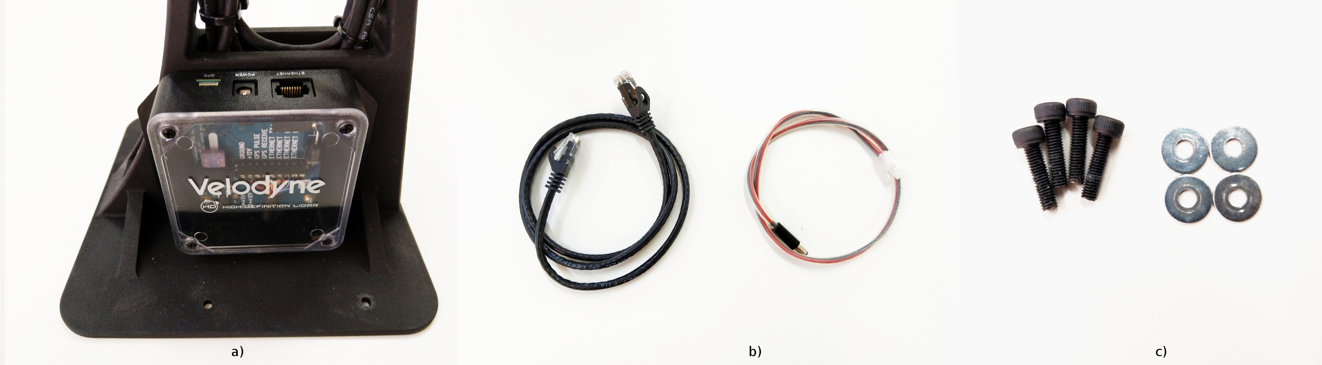
Figure: Velodyne VLP-16 kit contents
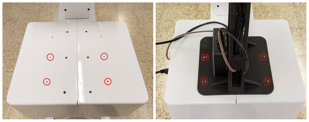
Figure: Steps to install the add-on
48.4 Starting velodyne drivers
Once the velodyne is connected to the robot, connect to the robot and start the velodyne startup application manually as shown below to start receiving data from the sensor.
ssh pal@tiago-0c
pal-start velodyne
Once the velodyne application is started, velodyne data should be published in ROS. This could be verified by the following commands:
ssh pal@tiago-0c
rostopic list | grep velodyne
The laser scan information from the velodyne can be access from the topic /scan_velodyne.
49 Optris Thermal Camera
49.1 Overview
The Optris Thermal Camera add-on [12] is a thermographic camera with its thermal sensitivity of 40 mK, specifically suited for detection of slightest temperature differences, making it indispensable in quality control of products and in medical prevention. The measurement temperature ranges from -20 °C to 100 °C, 0 °C to 250°C and 120 °C to 900 °C, and spectral range of 7.5 to 14 μm, with an accuracy of ±2°C or ±2% (whichever is greater). Optris 450 sensor has been developed by Optris infrared measurements, that can be integrated into TIAGo++.
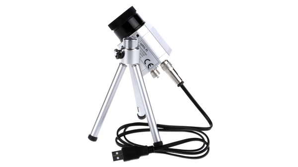
Figure: Optris PI450 add-on
49.2 Installation
The add-on device is meant to be attached on to the head of TIAGo++ and connected to the expansion panel of the robot as shown in figure below:
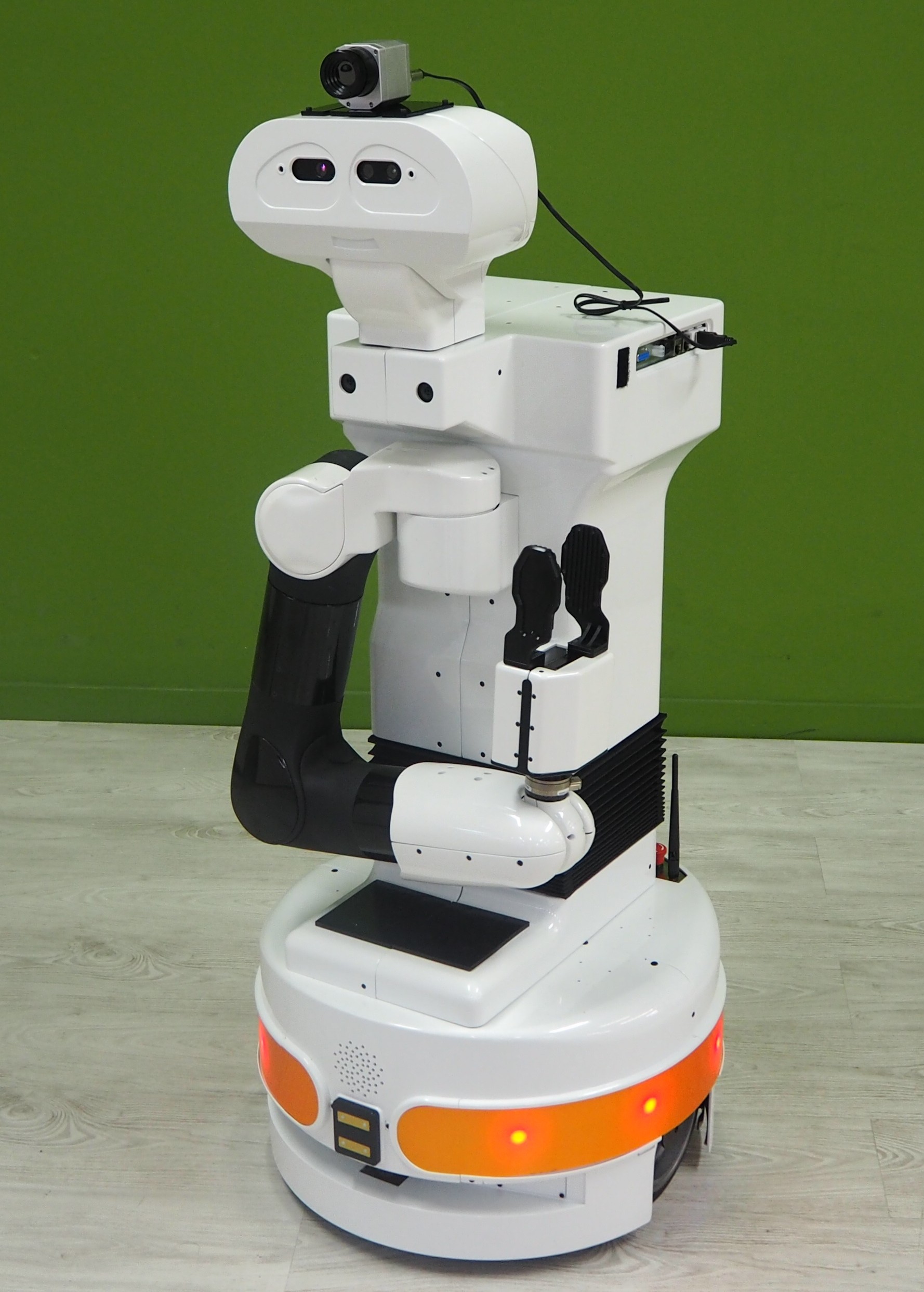
Figure: Optris thermal camera add-on attached to TIAGo++.
In order to attach the add-on the following components are provided in the kit:
Optris Thermal camera, see figure below
Mounting plate, see figure below
USB cable to connect the device to the expansion panel, see figure below
Specific fasteners DIN 912 M3x10 to attach the device to the head of the robot, see figure below
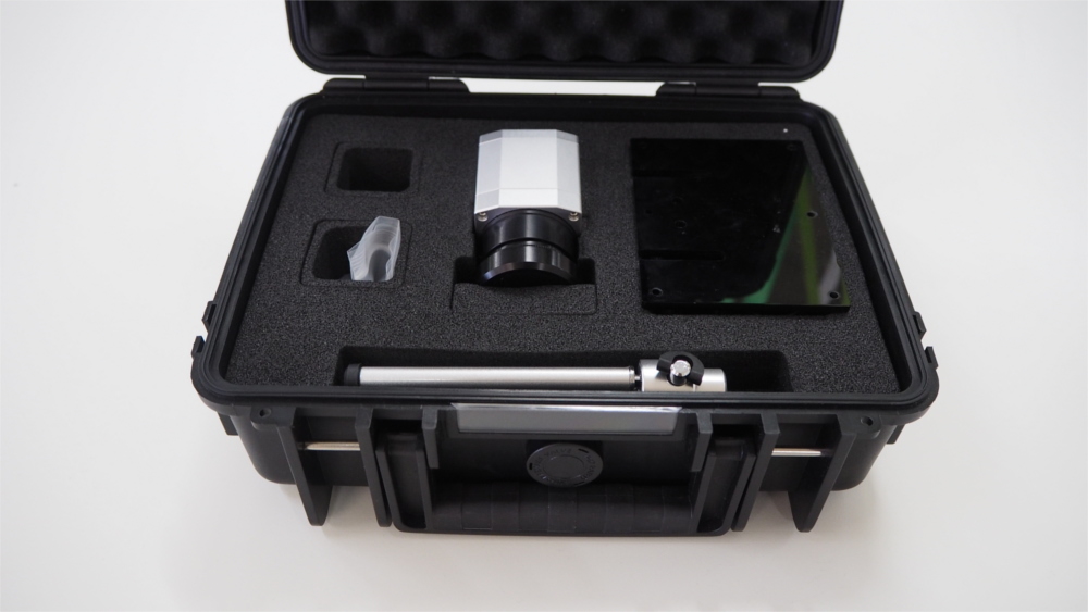
Figure: Velodyne VLP-16 kit contents
The installation steps are as follows:
First, attach the camera to the mounting panel with the provided fasteners DIN 7991 M4x8, see figure below
Use the fasteners DIN 912 M3x10 provided to attach the mounting plate along with the camera on top of the head of TIAGo++, see Figure: Steps to install the add-on
Connect the cable to the optris camera and then connect the USB cable end to the USB port of the expansion panel, see Figure: Steps to install the add-on
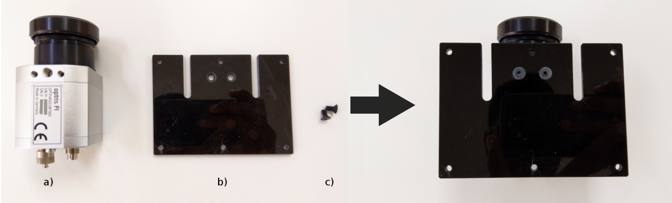
Figure: Steps to install the add-on
49.3 Starting optris drivers
Once the camera is connected to the robot, connect to the robot and start the thermal_camera startup application manually as shown below to start receiving data from the sensor.
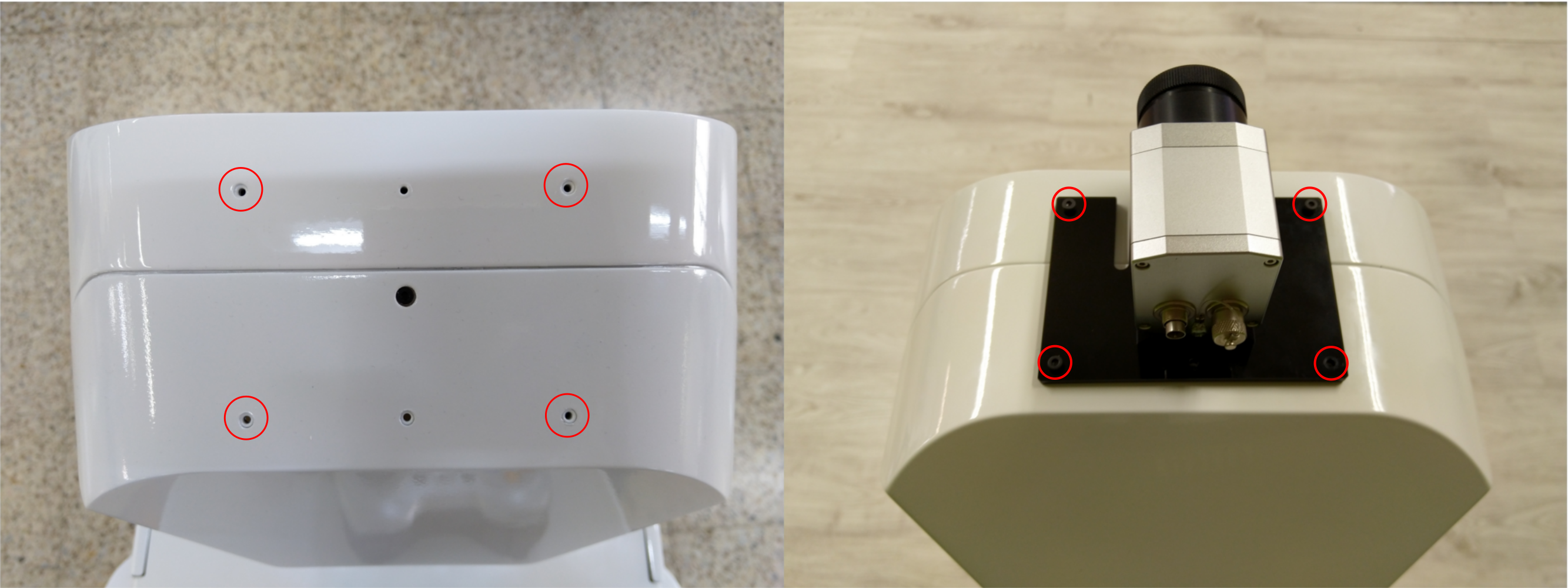
Figure: Steps to install the add-on
ssh pal@tiago-0c
pal-start thermal_camera
Once the thermal_camera application is started, thermographic information should be published in ROS. This could be verified by the following commands:
ssh pal@tiago-0c
rostopic list | grep optris
By default, the node will publish the thermal information in form of an image, but this cannot be visualized as the color_conversion node, which converts into displayable color representation is not used. In order to visualize the data, run the following commands inside the robot as shown below:
ssh pal@tiago-0c
pal-stop thermal_camera
roslaunch tiago_0_thermal_camera optris_camera.launch color_conversion:=true
Now, the data can be visualized from the topic: /optris/thermal_image_view as shown in the figure below:
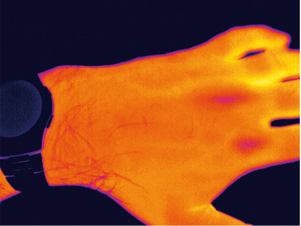
Figure: Visualized data
50 PAL gripper camera add-on
This chapter presents the add-on providing a small RGB camera on the PAL gripper end-effector shown in figure below. For instance, the camera on the gripper is very useful in the latter stages of a grasping task for commanding the end-effector with more precision.
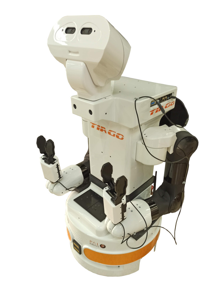
Figure: PAL gripper camera add-on mounted on TIAGo++
50.1 Overview
The PAL gripper add-on is composed of an endoscopic RGB camera with a 2 m USB cable mounted on a 3D printed support to attach it to the gripper, see figure below:
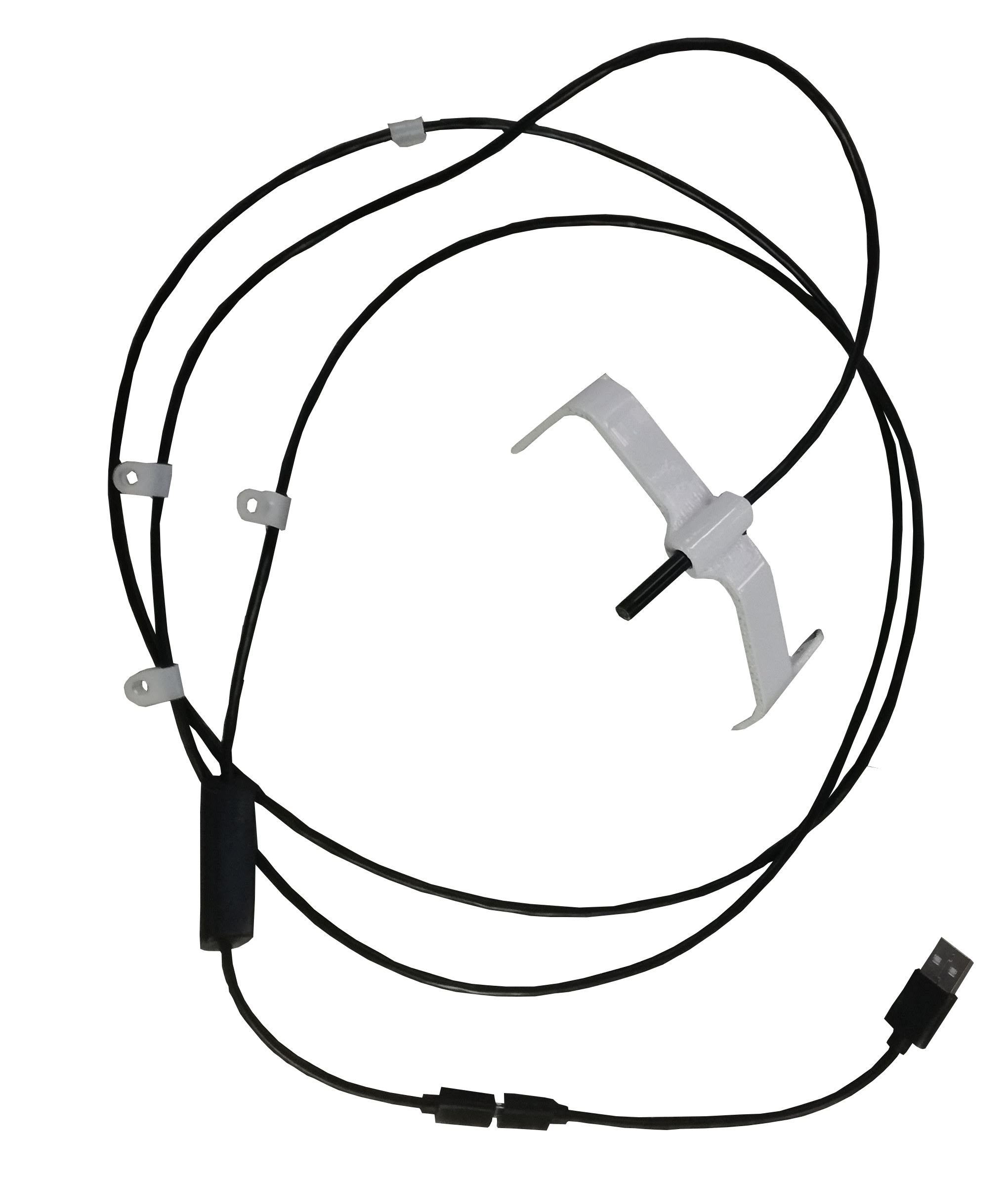
Figure: PAL gripper camera add-on
The cable has attached 4 fixation points as shown in figure below:
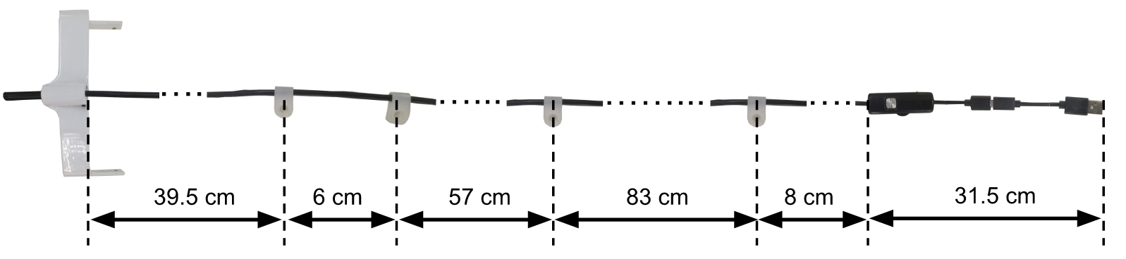
Figure: Specification of the gripper camera cable
50.2 Add-on installation
In order to mount the camera on the gripper a set of fasteners are provided:
4x M2,5x8 DIN 7991, in figure below see a, for the fixation points on the gripper.
2x M3x10 DIN 7991, in figure below see b, for the fixation points on the wrist.
1x M3x10 DIN 7991, in figure below see c, for the fixation point on the upper limb of the arm_${side}.
1x M3x16 DIN 7991, in figure below see c, for the fixation point on the lateral side of the upper part of the torso.
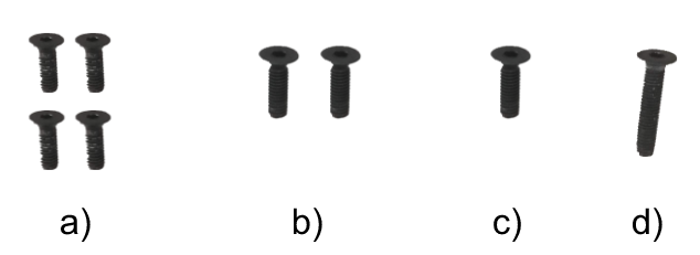
Figure: Fasteners to fix the camera gripper
The fixation points that must be used to attach the camera on the gripper of the left or right arm_${side} of TIAGo++ is shown in figure below.
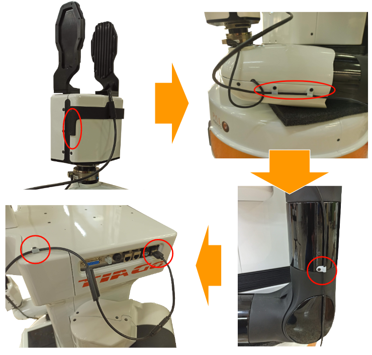
Figure: Mounting steps for the left arm_${side} of TIAGo++.
As tiago dual can have one or two endoscopic cameras, we are going to create a bash variable corresponding to the side. This way only modifying the value of the side variable you can reuse the following commands. Its very important that the opposite arm_${side} stays in home position, otherwise arm_${side}s can collide.
ssh pal@tiago-0c
side="right" #replace with "left" to do left camera
rosrun play_motion run_motion offer_${side}
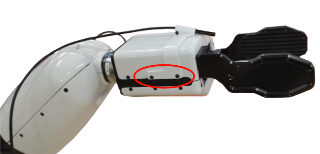
Figure: Mounting points on the gripper
Fix the 2 mounting points on the wrist cover as shown in Figure: Mounting points on the wrist, using the fasteners shown in Figure: Fasteners to fix the camera gripper b. In order to make sure that the cable between the camera and these fixation points is loose enough to prevent breakage by running the following joint motions:
rosrun play_motion move_joint arm_${side}_6_joint -1.39 3.0
rosrun play_motion move_joint arm_${side}_6_joint 1.39 3.0
rosrun play_motion move_joint arm_${side}_7_joint -2.07 3.0
rosrun play_motion move_joint arm_${side}_7_joint 2.07 3.0
rosrun play_motion move_joint arm_${side}_6_joint -1.39 3.0
rosrun play_motion move_joint arm_${side}_7_joint -2.07 3.0
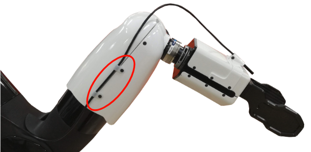
Figure: Mounting points on the wrist.
Run the following motion to have access to the fixation point on the upper limb of the arm as shown in Figure: Mounting point on the arm, and fix the next mounting point using the fastener shown in Figure: Fasteners to fix the camera gripper c
rosrun play_motion move_joint arm_${side}_3_joint 1.5 3.0
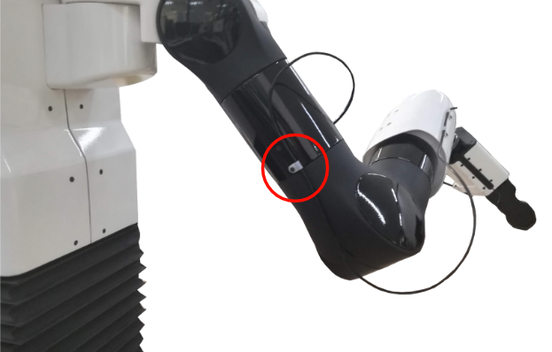
Figure: Mounting point on the arm
Make sure that the cable is loose enough between the fixation point of the upper limb and the wrist by running the following motions:
rosrun play_motion move_joint arm_${side}_3_joint -3.45 3.0
rosrun play_motion move_joint arm_${side}_6_joint 0.0 3.0
rosrun play_motion move_joint arm_${side}_4_joint 2.3 3.0
rosrun play_motion move_joint arm_${side}_5_joint 2.07 3.0
rosrun play_motion move_joint arm_${side}_5_joint -2.07 3.0
rosrun play_motion move_joint arm_${side}_4_joint -0.32 3.0
rosrun play_motion move_joint arm_${side}_5_joint 2.07 3.0
Run the following motion to better install the fixation point lateral side of the upper part of the torso asshown in Figure: Mounting point on the torso and USB connection, using the fastener shown in Figure: Fasteners to fix the camera gripper c
rosrun play_motion run_motion offer_${side}
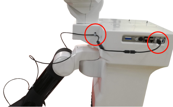
Figure: Mounting point on the torso and USB connection.
Make sure that the cable is loose enough between the fixation point on the upper limb of the arm and the torso by running the following motions:
rosrun play_motion move_joint arm_${side}_3_joint -3.11 3.0
rosrun play_motion move_joint arm_${side}_4_joint 0.5 3.0
rosrun play_motion move_joint arm_${side}_1_joint 2.68 3.0
rosrun play_motion move_joint arm_${side}_2_joint 1.02 3.0
rosrun play_motion move_joint arm_${side}_2_joint -1.5 10.0
rosrun play_motion move_joint arm_${side}_1_joint 0.07 6.0
rosrun play_motion move_joint arm_${side}_4_joint 1.0 3.0
rosrun play_motion move_joint arm_${side}_2_joint 0.0 3.0
rosrun play_motion move_joint arm_${side}_4_joint 0.0 3.0
rosrun play_motion move_joint arm_${side}_3_joint 1.55 3.0
rosrun play_motion move_joint arm_${side}_3_joint -3.48 10.0
Finally plug the USB connector to one of the ports on the expansion panel as shown in Figure: Mounting point on the torso and USB connection.
50.3 Running the camera driver
In order to start the driver of the camera run the following commands on a console (ensure the camera is plugged):
If you have two endoscopic cameras, ensure you start with only the right-one plugged. After the following commands, repeat it plugging the left one without unplugging the previous-one in a new terminal.
ssh pal@tiago-0c
rosrun tiago_bringup end_effector_camera.sh ${side}_camera
The different camera topics will be published in the /end_effector_<left/right>_camera namespace.
50.4 Visualizing the camera image
In order to check that the camera is working properly the image can be visualized from a development computer
as follows (make sure to set your development computer’s IP when exporting ROS_IP as explained in section 12.4 ROS communication with the robot):
export ROS_MASTER_URI=http://tiago-0c:11311
export ROS_IP=10.68.0.128
rosrun image_view image_view image:=/end_effector_camera/image_raw \ _image_transport:=compressed
An example of image provided by the gripper camera compared to the image of camera on the head is shown in figure below:
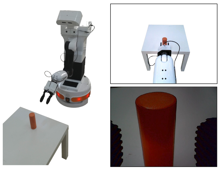
Figure: Example of images provided by the camera on the robot’s head (top-right) and the camera on the gripper (bottom-right)
51 PAL Hey5 camera add-on
This chapter presents the add-on providing a small RGB camera on the PAL Hey5 end-effector shown in figure below. The camera on the Hey5 is very useful for commanding the end-effector with more precision.
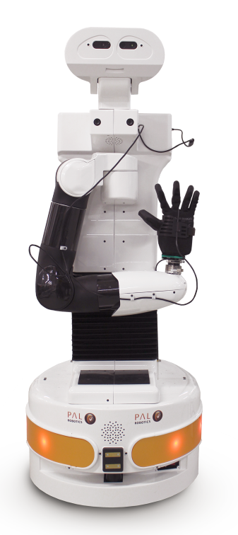
Figure: PAL Hey5 camera add-on mounted on TIAGo
51.1 Overview
The PAL Hey5 add-on is composed of an endoscopic RGB camera with a 2 m USB cable mounted on a 3D printed support to attach it to the Hey5, see figure below:
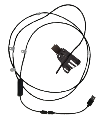
Figure: PAL Hey5 camera add-on
The cable has attached 4 fixation points as shown in figure below:
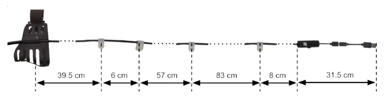
Figure: Specification of the Hey5 camera cable
51.2 Add-on installation
In order to mount the camera on the Hey5 a set of fasteners are provided:
2x M3x10 DIN 7991, in figure below see a, for the fixation points on the wrist.
1x M3x10 DIN 7991, in figure below see b, for the fixation point on the upper limb of the arm.
1x M3x10 DIN 7991, in figure below see c, for the fixation point on the lateral side of the upper part of the torso.
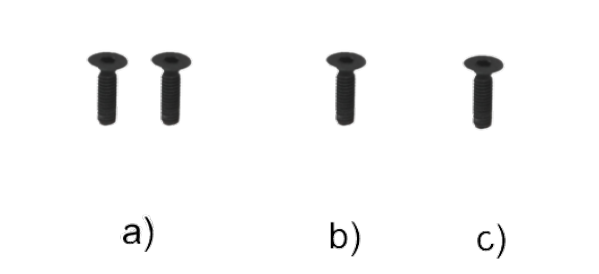
Figure: Fasteners to fix the camera Hey5
Follow the procedure below to properly attach the camera and its cable to TIAGo:
Run the
Offer Handmotion in order to fix the endoscopic Hey5 support as shown in Figure: Mounting points on the Hey5. The motion can be run from command line as follows:
ssh pal@tiago-0c
rosrun play_motion run_motion offer_hand
Notice that the support comes with 1x M2.5x6 DIN 912 screw that is used to fix the endoscopic camera to the support.
This screw can also be shown in figure below:
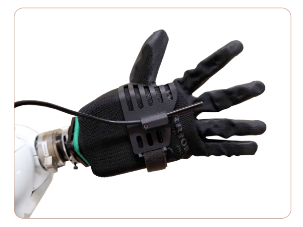
Figure: Mounting points on the Hey5.
Fix the 2 mounting points on the wrist cover as shown in Figure: Mounting points on the wrist, using the fasteners shown in Figure: Fasteners to fix the camera Hey5 a. In order to make sure that the cable between the camera and these fixation points is loose enough to prevent breakage by running the following joint motions:
rosrun play_motion move_joint arm_6_joint -1.39 3.0
rosrun play_motion move_joint arm_6_joint 1.39 3.0
rosrun play_motion move_joint arm_7_joint -2.07 3.0
rosrun play_motion move_joint arm_7_joint 2.07 3.0
rosrun play_motion move_joint arm_6_joint -1.39 3.0
rosrun play_motion move_joint arm_7_joint -2.07 3.0
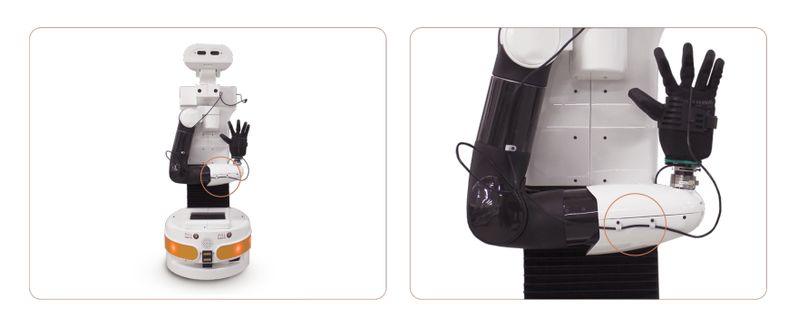
Figure: Mounting points on the wrist.
Run the following motion to have access to the fixation point on the upper limb of the arm as shown in Figure: Mounting point on the arm, and fix the next mounting point using the fastener shown in Figure: Fasteners to fix the camera Hey5 b:
rosrun play_motion move_joint arm_3_joint -2.0 3.0
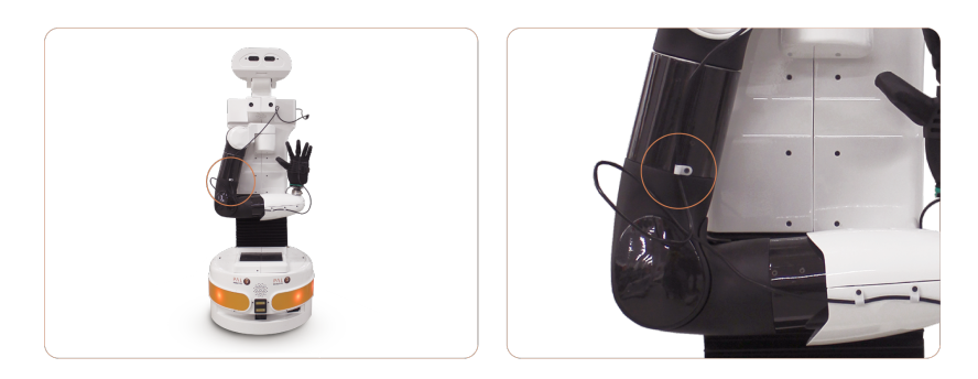
Figure: Mounting point on the arm.
Make sure that the cable is loose enough between the fixation point of the upper limb and the wrist by running the following motions:
rosrun play_motion move_joint arm_3_joint -3.45 3.0
rosrun play_motion move_joint arm_6_joint 0.0 3.0
rosrun play_motion move_joint arm_4_joint 2.3 3.0
rosrun play_motion move_joint arm_5_joint 2.07 3.0
rosrun play_motion move_joint arm_5_joint -2.07 3.0
rosrun play_motion move_joint arm_4_joint -0.32 3.0
rosrun play_motion move_joint arm_5_joint 2.07 3.0
Run the following motion to better install the fixation point lateral side of the upper part of the torso as shown in figure below, using the fastener shown in Figure: Fasteners to fix the camera Hey5 c:
rosrun play_motion move_joint arm_3_joint 0.0 3.0
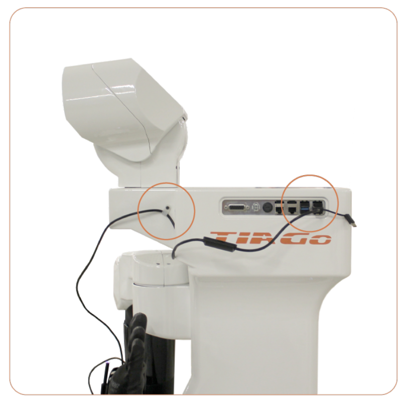
Figure: Mounting point on the torso and USB connection.
Make sure that the cable is loose enough between the fixation point on the upper limb of the arm and the torso by running the following motions:
rosrun play_motion move_joint arm_3_joint -3.11 3.0
rosrun play_motion move_joint arm_4_joint 0.5 3.0
rosrun play_motion move_joint arm_1_joint 2.68 3.0
rosrun play_motion move_joint arm_2_joint 1.02 3.0
rosrun play_motion move_joint arm_2_joint -1.5 10.0
rosrun play_motion move_joint arm_1_joint 0.07 6.0
rosrun play_motion move_joint arm_4_joint 1.0 3.0
rosrun play_motion move_joint arm_2_joint 0.0 3.0
rosrun play_motion move_joint arm_4_joint 0.0 3.0
rosrun play_motion move_joint arm_3_joint 1.55 3.0
rosrun play_motion move_joint arm_3_joint -3.48 10.0
Finally plug the USB connector to one of the ports on the expansion panel as shown in Figure: Mounting point on the torso and USB connection.
51.3 Running the camera driver
In order to start the driver of the camera run the following commands on a console (ensure the camera is plugged):
ssh pal@tiago-0c
rosrun tiago_bringup end_effector_camera.sh
The different camera topics will be published in the /end_effector_camera namespace.
51.4 Visualizing the camera image
In order to check that the camera is working properly the image can be visualized from a development
computer as follows (make sure to set your development computer’s IP when exporting ROS_IP as explained in
Section 12.4 ROS communication with the robot):
export ROS_MASTER_URI=http://tiago-0c:11311
export ROS_IP=10.68.0.128
rosrun image_view image_view image:=/end_effector/camera/image_raw \ _image_transport:=compressed
An example of image provided by the Hey5 camera compared to the image of camera on the head is shown in figure below:
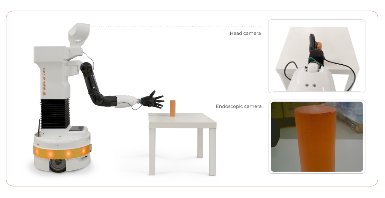
Figure: Example of images provided by the camera on the robot’s head (top-right) and the camera on the Hey5 (bottom-right)
52 Windows tablet
52.1 Introduction
The tablet kit for TIAGo++ is composed of the following components which are depicted in figure below:
Tablet
Ethernet cable
Power cable with a 12 V to 5 V DC/DC
Mounting 3D printed parts and fasteners
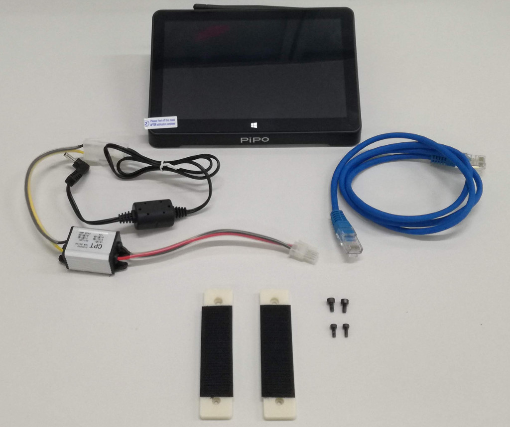
Figure: Tablet kit components
52.2 Tablet installation
This Section presents how to install the tablet kit on TIAGo++.
52.2.1 Mounting the tablet support
The tablet can be attached on top of TIAGo++ by first mounting two small 3D printed supports provided of velcro stripes. The supports must be fastened using the mounting points of the head shown in figure below (a). Note that depending on the version of the kit there might be 2 types of fasteners, 2 thinner ones and 2 thicker ones. In that case, use the thinner ones on the appropriate support holes and screw them on the frontal part of the head as shown in figure below (b). The thicker fasteners must be used in the mounting points of the rear part of the head, see figure below (c). The final mounted supports can be seen in figure below (d).
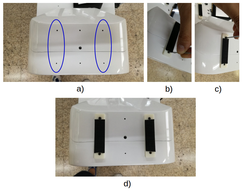
Figure: Mounting the tablet support
52.2.2 Tablet fixation and connection
Once the support is mounted the tablet can be fixed using the velcro stripes as shown in figure below:
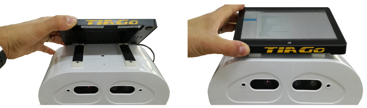
Figure: Tablet fixation on top of the head
Then, the tablet can be connected to the expansion panel as shown in Figure: Tablet connection to the expansion panel. There is an ethernet cable that can be connected to any of the GigE ports of the expansion panel and a power supply cable, including a DC/DC converter, to connect to the power connector of the panel.
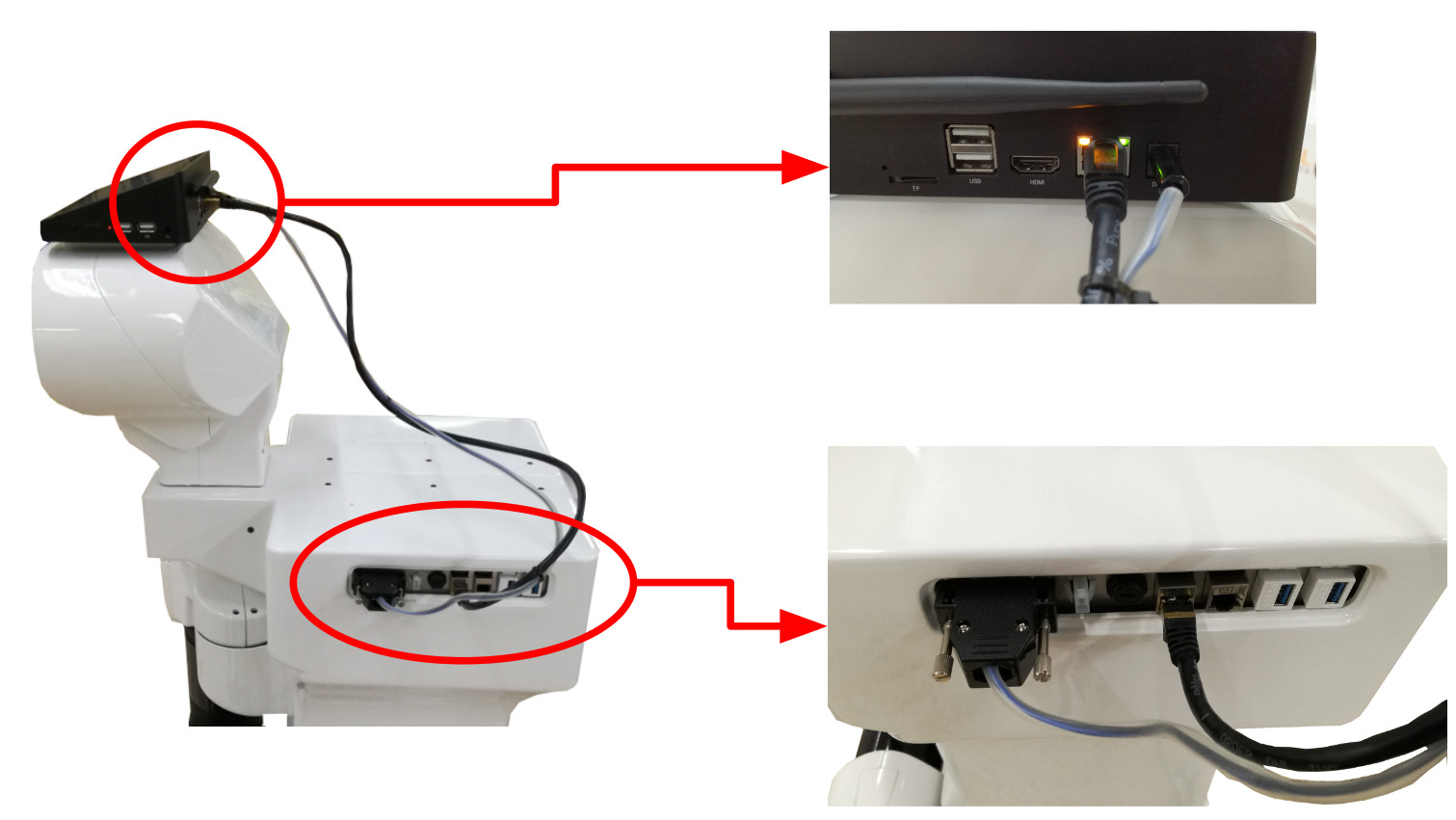
Figure: Tablet connection to the expansion panel
The DC/DC provided, which converts from 12 V supplied by the expansion panel to the 5 V required by the tablet, can be attached using the velcro patches as shown in figure below:
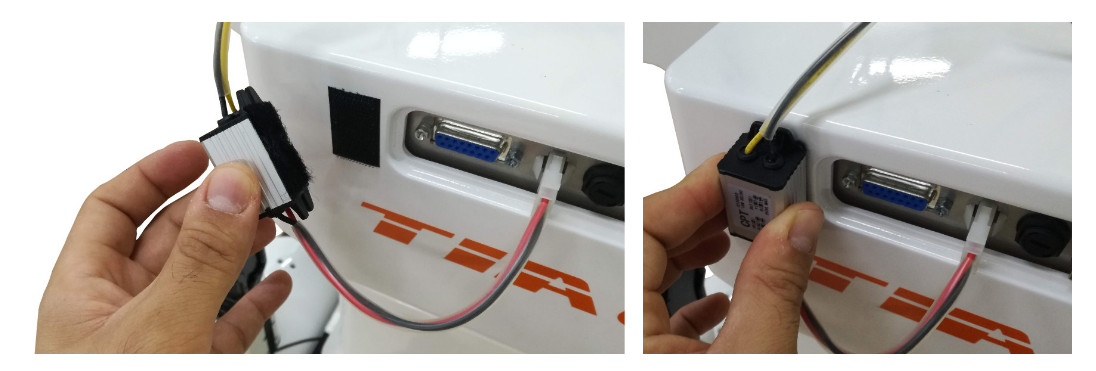
Figure: Fixation of the DC/DC converter
52.3 Testing the tablet
This Section presents how to test that the tablet installed in TIAGo++ works properly.
First of all press the On/Off button of the tablet placed on one of its sides as shown in figure below:
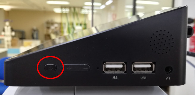
Figure: Turning on the tablet
Once the Windows OS has booted go to the notification menu to configure windows as an orientated tablet using the botom icon shown in the figure below:
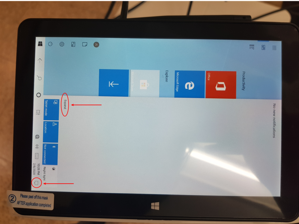
Figure: Configure windows as tablet
Ensure the tablet mode is selected, orientate the screen using the internal IMU of the Pipo and block the orientation as shown in the figure below:
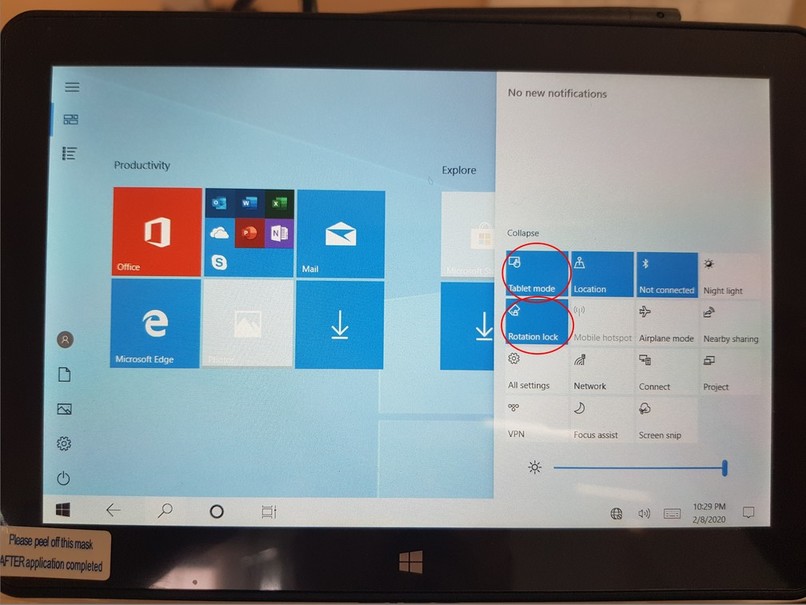
Figure: Tablet mode and orientation
Click the default browser Microsoft Edge (or preferably download google chrome as our application is fully supported only on it) as shown in the figure below:
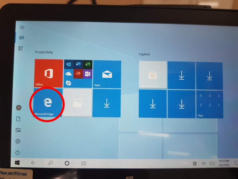
Figure: Tablet mode and orientation
Type http://control:8080 in the URL bar in order to connect to the WebCommander of the robot. Note that the screen shown in Figure: WebCommander shown in the tablet should show up. In that case, the tablet is up and running properly and it is able to communicate with the robot’s onboard computer.
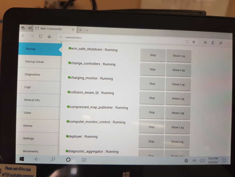
Figure: WebCommander shown in the tablet
52.4 Apps development
In order to communicate with the onboard robot’s computer using ROS the user must use roslibjs, which is
a JavaScript library to allow interaction with a ROS system from a Web browser. It uses WebSockets to
connect with the rosbridge running in the robot at http://tiago-Xc:9090, whereXis the serial number of
the robot without leading 0s. rosbridge provides a JSON API to ROS through:
Topics
Services
Actions
53 Demos
53.1 Demos accessible via WebCommander
All the demos of this group are accessible via WebCommander in the tab Robot Demos
53.1.1 Gravity compensation
This demo is started by pressing the Gravity compensation button.
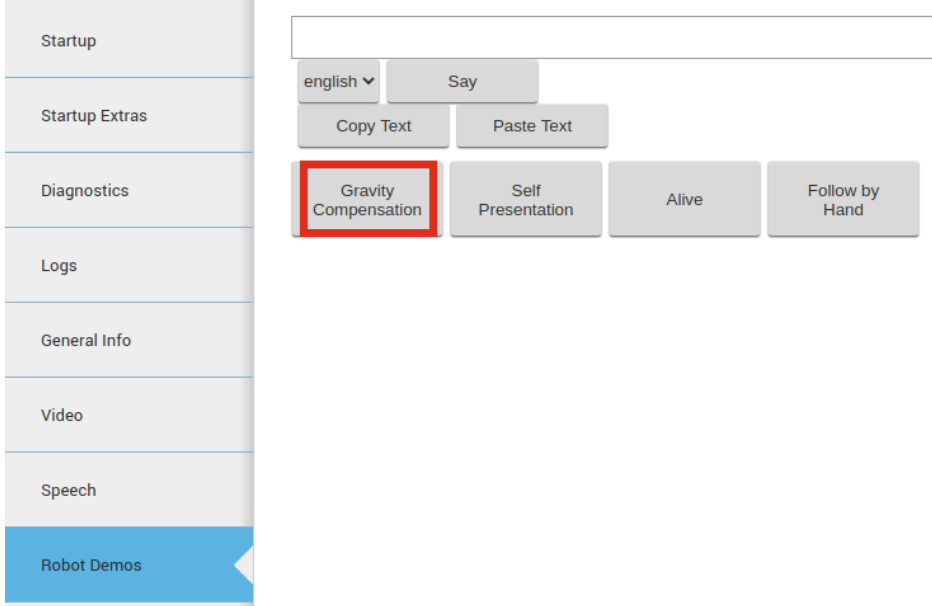
Figure: Button to start the gravity compensation demo
This demo consists in switching the arm from position control to gravity compensation control, which uses the effort interface based on current control. When this mode is activated the user can modify the kinematic configuration of the robot’s arm by pushing the different links. This control mode is useful, for example, to perform kinestetic teaching for learning-by-demonstration purposes as explained in this chapter and shown in the online video in https://www.youtube.com/watch?v=EjIggPKy0T0
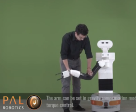
Figure: Gravity compensation demo allows changing the arm pose by simply pushing the links of the robot
In order to stop the demo it is necessary to press the same button that reads now CANCEL Gravity Compensation.
This will switch from the gravity compensation controller to the position controllers of the arm motors.
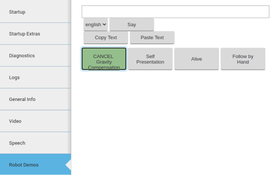
Figure: Button to stop the gravity compensation demo
53.1.2 Self presentation
Warning
Before running this demo make sure that there is a clearance of 1.5 m around the robot as several upper body movements will be run during the demo that might cause collisions with the environment or person around the robot.
This demo will make the robot to introduce itself to the audience by using voice synthesis and different movements to show some of its capabilities and features.
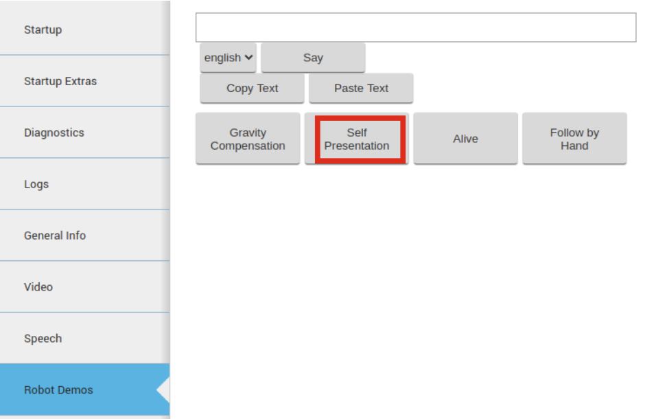
Figure: Button to start the self presentation demo
In order to cancel the demo during its execution or right after its ending please press the same button that now reads CANCEL Self Presentation.
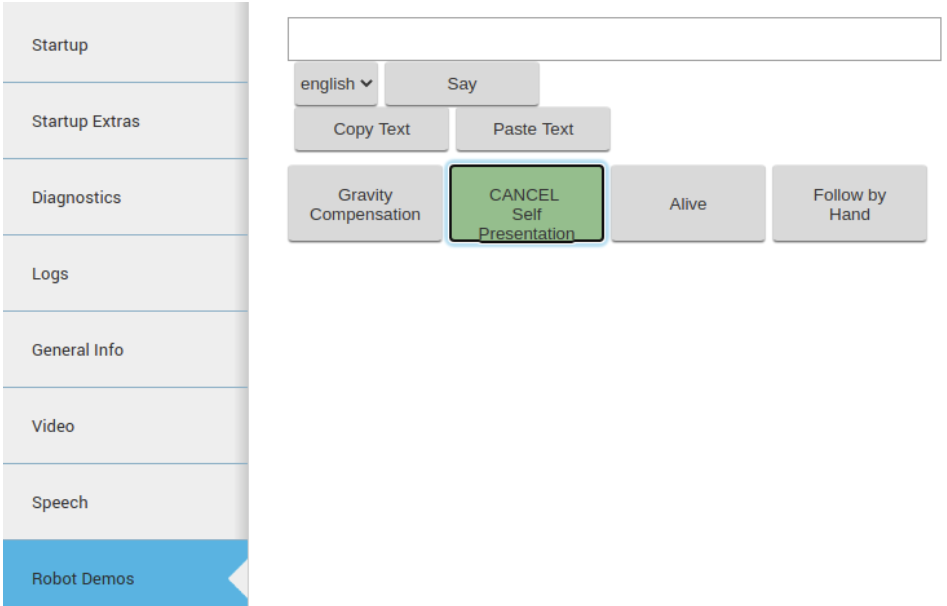
Figure: Button to stop the gravity compensation demo
53.1.3 Alive demo
This demo makes TIAGo++ keep repeating small upper body movements in loop as if it was alive. This is useful to have the robot doing something rather than just waiting still for some action to be triggered. Before triggering any other upper body movement is important to cancel first the demo.
Warning
Before starting the demo it is important to have some clearance around the robot as the first movement performed is a Home motion.
In order to start the demo press the Alive.
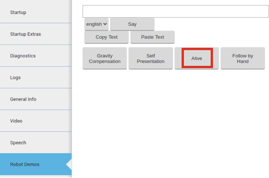
Figure: Button to stop the gravity compensation demo
In order to stop the demo just press the same button that now reads CANCEL Alive.
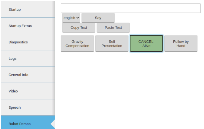
Figure: Button to stop the alive demo
53.1.4 Follow by Hand demo
This demo makes the robot to extend its arm forward and starts explaining using voice synthesis the purpose of the demo. Once the movement is completed a person can start pulling or pushing the arm in the main directions and the robot base will move towards that direction. This demo shows an application of the gravity compensation controller applied to command the base of the robot by using direct physical interaction with the arm.
Warning
When grabbing the arm of the robot it is recommended to grab it in the end-tip of the wrist as shown in the following picture.
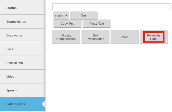
Figure: Button to start the Follow by Hand demo
The demo can be started by pressing the button Follow by Hand.
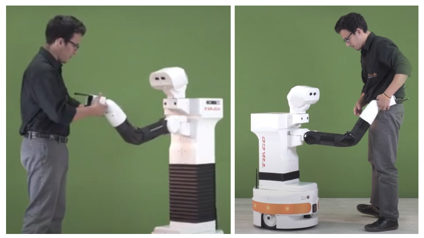
Figure: How to grab the arm of the robot during the Follow by the Hand demo
A video showing the demo can be found in https://youtu.be/EjIggPKy0T0?t=51 at second 51.
To stop the demo just press the same button than now reads CANCEL Follow by Hand.
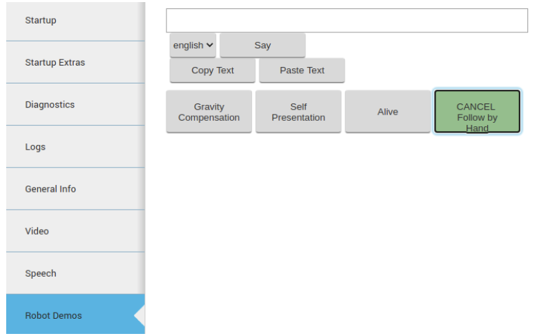
Figure: Button to stop the Follow by Hand demo
53.2 Learning-by-demonstration
This demo shows how to make the robot learn arm movements by kinesthetic teaching.
The details of the demo and the instructions on how to download the required packages, build them and how to run it are explained in the README.md file of the github’s respository at https://github.com/pal-robotics/learning_gui.
54 Troubleshooting
54.1 Overview
This chapter presents typical issues that may appear when using TIAGo++ and possible solutions. Please check the tables below carefully before reporting an issue to the support platform in order to find solutions faster.
54.2 Startup issues
# |
Issue description |
Possible solutions |
|---|---|---|
1.1 |
The robot does not power up when pressing the On/Off button of the rear panel |
Make sure that the electric switch is pressed, i.e. its red light is ON |
1.2 |
After several days of not using the robot does not power up |
Make sure that the battery is charged. Connect the charger and try to turn the robot on again after a couple of minutes |
1.3 |
After several deays of not using the robot, the batteries, which were charged, are now empty |
If the the electric switch was left pressed it is possible that the batteries have been completely discharged |
54.4 Upperbody movements issues
# |
Issue description |
Possible solutions |
|---|---|---|
3.1 |
Pre-defined movements do not work |
Make sure in WebCommander -> Startup -> play_motion that this node is running. Otherwise press the ’Start’ button to re-launch it. If this is not the case, try to reboot the robot and check if the problem persists. |
3.2 |
The torso does not move when trying to control it with the joystick |
Make sure that the arm is not in collision with some other part of the robot. If so, try first running the pre-defined movement |
3.3 |
I have defined a new movement for |
Make sure that none of the joints of your motion is being controlled by other nodes. For example, if your movement includes the head joints, make sure to stop the |
3.4 |
I have defined a new movement for |
Make sure to set to false the |
54.5 Text-to-speech issues
# |
Issue description |
Possible solutions |
|---|---|---|
4.1 |
The robot does not speak when sending a voice command |
Make sure that the volume is set appropriately. Check that WebCommander -> Seetings -> Playback Volume has not been lowered |
54.6 Network issues
# |
Issue description |
Possible solutions |
|---|---|---|
5.1 |
I have configured TIAGo++’s network to connect to my LAN but it does not work and I have no longer access to the robot via WiFi |
Connect a computer to one of the Ethernet ports of the expansion panel and open a web browser to connect to |
5.2 |
I have applied on TIAGo++ a new network configuration but after rebooting the robot the changes made have been reverted |
To save permanently the new network configuration make sure to press ’Save’ and ’Confirm’ after pressing ’Apply change’. Otherwise the network configuration changes are not save permanently. |
54.7 Gazebo issues
# |
Issue description |
Possible solutions |
|---|---|---|
6.1 |
If you are using a computer with a non-dedicated GPU and run into issues with the lasers in simulation |
You would need to change this environment variable before launching the simulation: export LIBGL_ALWAYS_SOFTWARE=1 |
55 Customer service
55.1 Support portal
All communication between customers and PAL Robotics is made using tickets in a helpdesk software.
This web system can be found at http://support.pal-robotics.com. The next figure shows the initial page of the site.
New accounts will be created on request by PAL Robotics.
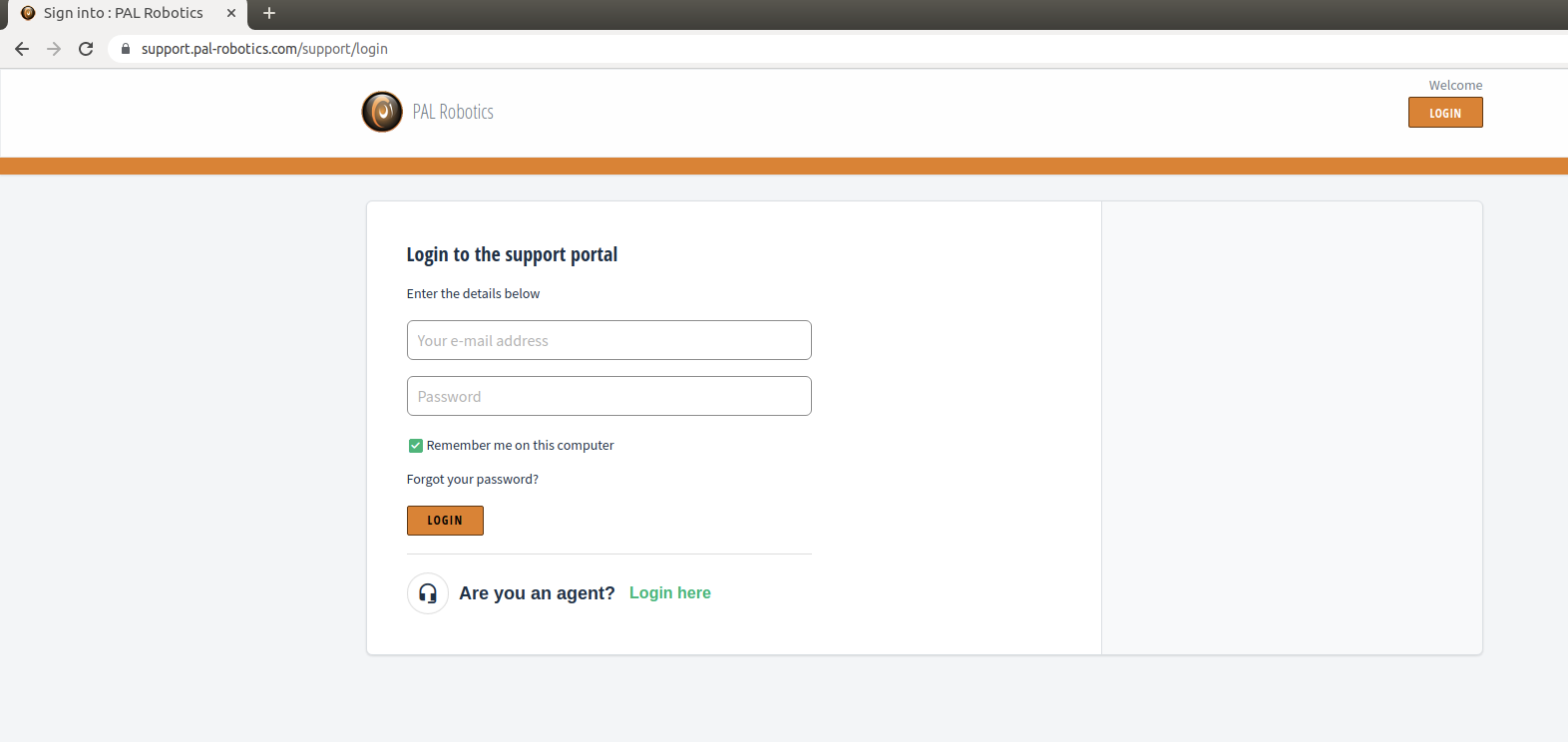
Figure: PAL Robotics support website
Once the customer has entered the system (Figure: Helpdesk), two tabs can be seen: Solutions and Tickets.
The Solution section contains FAQs and News from PAL Robotics.
The Tickets section contains the history of all tickets the customer has created.
Figure: Helpdesk
The next figure shows the ticket creation webpage.
Figure: Ticket creation
55.2 Remote support
A technician from PAL Robotics can give remote support. This remote support is disabled by default, so the customer has to activate it manually (Please refer to the 13.3.11 Settings Tab for further details).
Using an issue in the support portal, the PAL technician will provide the IP address and port the customer has to use.