1 ARI User Manual
Thank you for choosing PAL Robotics. This User Manual contains information related to the ARI robot developed by PAL Robotics. Every effort has been made to ensure the accuracy of this document. All the instructions must be strictly followed for proper product usage. The software and hardware described in this document may be used or replicated only in accordance with the terms of the license pertaining to the software or hardware. Reproduction, publication, or duplication of this manual, or any part of it, in any manner, physical, electronic or photographic, is prohibited without the explicit written permission of PAL Robotics.
1.1 Disclaimers General
Disclaimer ARI
ARI and its components and accessories are provided “as is” without any representations or warranties, express or implied. PAL Robotics makes no representations or warranties in relation to its products or the information and materials related to them, other than the ones expressly written in this User Manual. In no event shall PAL Robotics be liable for any direct, indirect, punitive, incidental, special or consequential damages to property or life, whatsoever, arising out of or connected with the use or misuse of ARI or the rest of our products.
User Manual Disclaimer
Please note that each product application may be subject to standard of identity or other will comply with such regulations in any country. It is the user’s responsibility to ensure that the incorporation and labeling of ARI complies with the regulatory requirements of their markets.
No warranties
This User Manual is provided “as is” without any representations or warranties, express or implied. PAL Robotics makes no representations or warranties in relation to this User Manual or the information and materials provided herein. Although we make a reasonable effort to include accurate and up to date information, without prejudice to the generality of this paragraph, PAL Robotics does not warrant that the information in this User Manual is complete, true, accurate or non-misleading. The ARI User Manual is provided solely for informational purposes. You should not act upon information without consulting PAL Robotics, a distributor, subsidiary or appropriate professional.
Limitations of liability
PAL Robotics will not be liable (whether under the law of contract, the law of torts or otherwise) in relation to the contents of, or use of, or otherwise in connection with, this User Manual: * to the extent that this User Manual is provided free-of-charge, for any direct loss;
for any indirect, special or consequential loss; or
for any business losses, loss of revenue, income, profits or anticipated savings, loss of contracts or business relationships, or loss of reputation or goodwill.
These limitations of liability apply even if PAL Robotics has been expressly advised of the potential loss.
Exceptions
Nothing in this User Manual Disclaimer will exclude or limit any warranty implied by law that it would be unlawful to exclude or limit; and nothing in this User Manual Disclaimer will exclude or limit PAL Robotics’s liability in respect of any: * personal injury caused by PAL Robotics’s negligence;
fraud or fraudulent misrepresentation on the part of PAL Robotics; or
matter which it would be illegal or unlawful for PAL Robotics to exclude or limit, or to attempt or purport to exclude or limit, its liability.
Reasonableness
By using this User Manual, you agree that the exclusions and limitations of liability set out in this User Manual Disclaimer are reasonable. If you do not think they are reasonable, you must not use this User Manual.
Other parties
You accept that, PAL Robotics has an interest in limiting the personal liability of its officers and employees. You agree that you will not bring any claim personally against PAL Robotics’s officers or employees in respect of any losses you suffer in connection with the User Manual. Without prejudice to the foregoing paragraph, you agree that the limitations of warranties and liability set out in this User Manual Disclaimer will protect PAL Robotics’s officers, employees, agents, subsidiaries, successors, assigns and sub-contractors, as well as PAL Robotics.
Unenforceable provisions
If any provision of this User Manual Disclaimer is, or is found to be, unenforceable under applicable law, that will not affect the enforceability of the other provisions of this User Manual Disclaimer.
2 ARI
2.1 What is ARI
ARI is PAL Robotics’ humanoid platform specifically created for Human-Robot-Interaction and to perform front-desk activities. ARI is a high-performance robotic platform designed for a wide range of multimodal expressive gestures and behaviors, suitable for Human-Robot-Interaction, perception, cognition and navigation. It is important to clarify the intended usage of the robot prior to any kind of operation. ARI is designed to be operated in a controlled environment, under supervision by trained staff at all times. ARI’s hardware and software enables research and development of activities in the following areas:
Navigation and SLAM
Manipulation
Perception
Speech recognition
Human-Robot interaction
2.2 Package contents
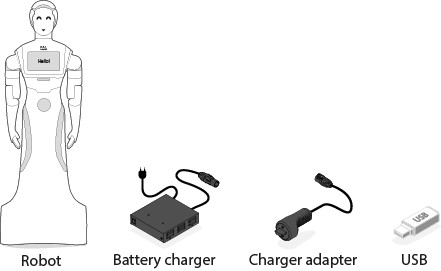
This section includes a list of items and accessories that come with ARI. Make sure the items in the following list are present:
ARI Robot
Battery Charger and Charger Adapter
USB flash drive with installation software
Docking station (optional)
Joystick (optional)
NVIDIA Jetson (optional)
2.3 ARI components
The following is a list of ARI’s components:
Humanoid Torso
2 DoF head
16 RGB LEDs per ear
Eyes LCD screens with custom animations
40 RGB LED ring on the back
Touchscreen 10.1” 1200x800 Projected Capacitive
802.11 a/b/g/n/ac/ad 5 GHz and 2.4 GHz
Ethernet 1000 BaseT
4 x High Performance Digital Microphones array
Optional head camera: Head Camera Sony 8MegaPixel (RGB), Head Intel Realsense D435i (RGB-D).
Torso Camera Intel Realsense D435i (RGB-D)
Torso Back Intel Realsense D265 (stereo-fisheye)
2x HiFi Full-range Speakers
Thermal camera (optional)
2.3.1 Battery
ARI comes with a 40 Ah Li-ion battery and can be charged manually or by using the docking station, that provides eight hours of autonomy before charging is needed. Below are further details on battery options:
The manual charger or the dock station can charge ARI in five hours from a completely empty battery to fully charged.
An increased autonomy can be achieved with a 60Ah battery pack, that will last 12 hours and will charge in eight hours.
2.3.2 Onboard computer
The specifications of ARI´s onboard computer depends on the configuration options that you have requested. The different possibilities are shown here:
CPU |
Intel i5/i7 |
RAM |
8/16/32 GB |
Hard disc |
250 GB or 500 GB |
Wi-Fi |
Yes |
2.3.3 Electric Switch
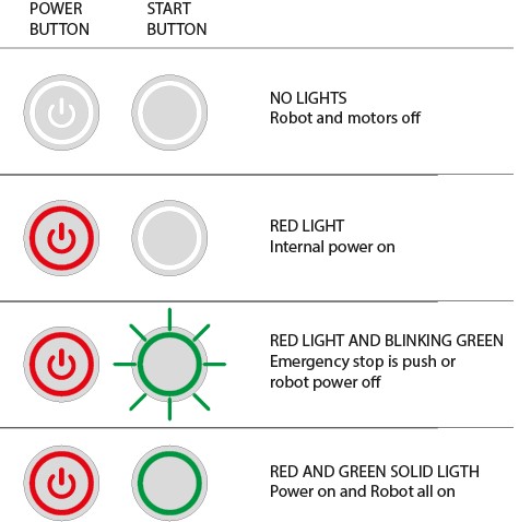
The Power Button is the main power control switch. Before turning ARI ON make sure first that this switch is ON, i.e. its red light indicator is ON.
When ARI is not going to be used for a long period, press the switch so that its red light indicator turns OFF.
Please note: This switch should not be turned OFF before using the ON/OFF button to turn OFF the onboard computer of the robot.
Turning OFF this switch will instantaneously cut the power supply to all the robot components, including the onboard computer. Do not use this switch as an emergency stop. For the emergency stop please refer to Emergency Stop.
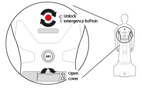
Before switching ARI ON: unlock the emergency button and open the lid to access the power buttons at the back of the robot.
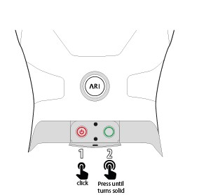
To switch ARI ON: push the left button, it will turn RED. Then press the right button until it turns solid GREEN. If the GREEN button is blinking check that the emergency button has been released.
2.3.4 Connectivity
ARI is equipped with a dual band wireless card with the following specifications: 802.11.a/b/g/n/ ac 5GHz, 867 Mbps , Bluetooth 4.4, LTE Capable.
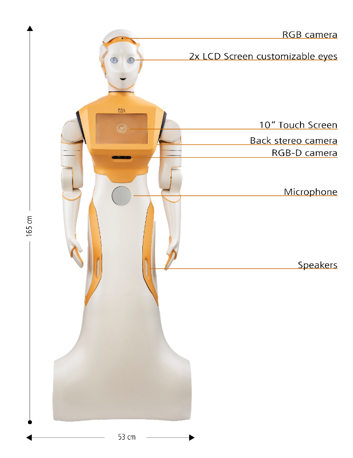
2.4 ARI description
ARI´s main dimensions are summarized in the table below:
Height |
165 cm |
Width |
53cm |
Depth |
75cm |
DoF Head |
2 |
DoF Arms |
4 (x2) Optional |
DoF Hands |
1 (x2) Optional |
DoF Mobile Base |
2 |
2.4.1 Payload
ARI’s arm payload, max speed, battery life, computing power, communication, AI and DoF are summarised in the following table:
Arm payload |
0.5 Kg |
Max Speed |
1.5 m/s |
Battery life |
Up to 12h |
Computing Power |
Intel i5/i7, up to 32GB RAM |
AI |
NVIDIA® embedded GPU |
Communication |
WiFi, Bluetooth, USB, Ethernet |
DoF |
Up to 14 DoF |
2.4.2 User panel
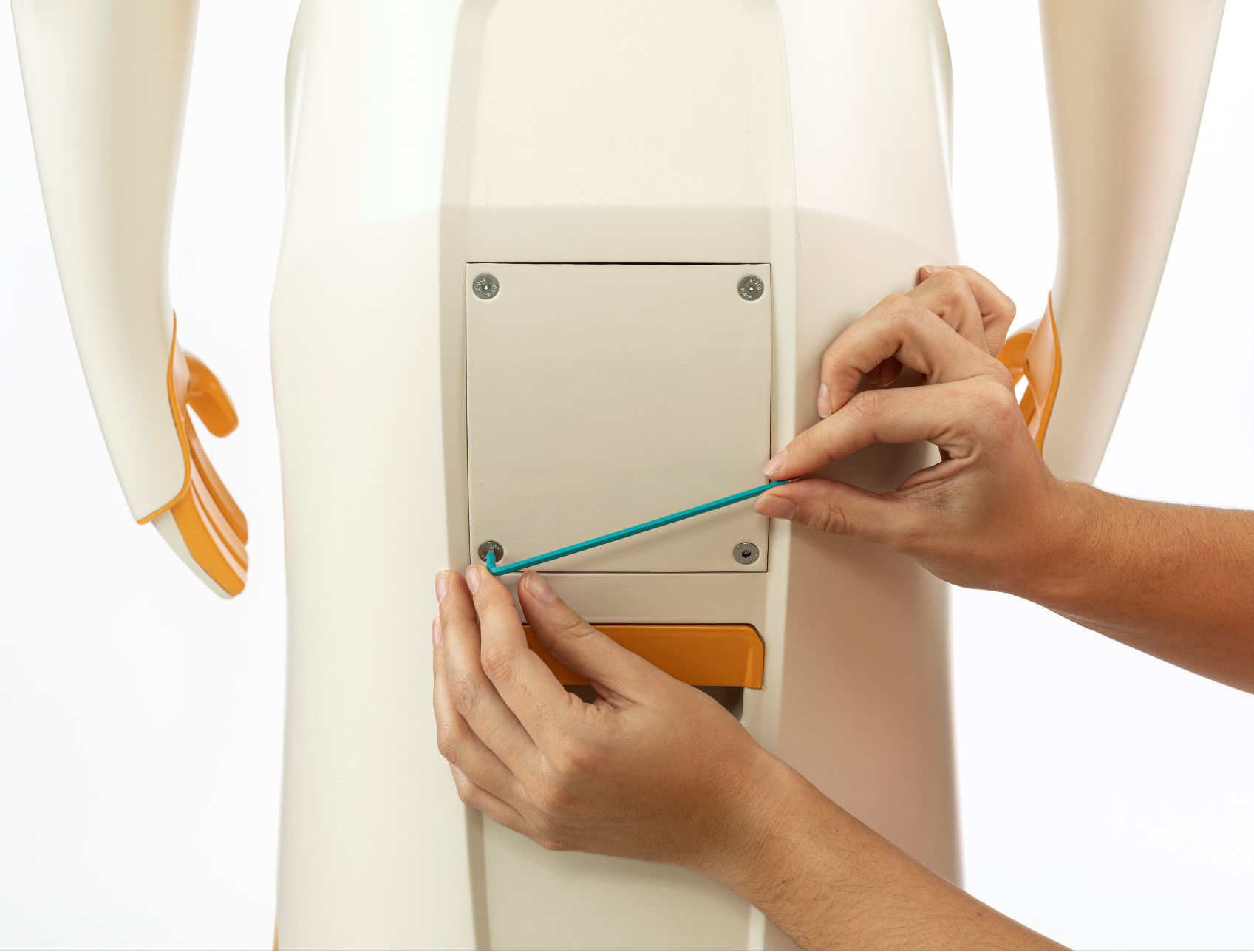
It is possible to access the user panel by removing the cover as shown in the figure below:
2.4.3 Main PC connectors
These are as follows:
1x Gigabyte Ethernet
2 x USB 3.0
HDMI
Audio In/Out port
2.4.4 External power connectors
These are as follows:
12V/ 3A Powe
2.4.5 Nvidia GPU Embedded PC
The details are as follows:
2 x USB 3.0
Jetson buttons
3 Regulatory
Safety is important when working with ARI. This section provides an overview of safety issues, general usage guidelines to maintain safety, and some safety-related design features. Read these instructions carefully to ensure the safety of people and surroundings and to prevent damages to the environment and to the robot. Follow these instructions everytime the robot is used.
3.1 Safety
Read the following safety precautions before setting up, using and maintaining the robot. Incorrect handling of this product could result in personal injury or physical damage to the robot. The manufacturer assumes no responsibility for any damage caused by mishandling what is beyond normal usage defined in this product manual.
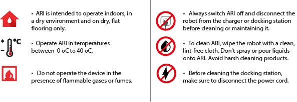
Environment
ARI is intended to operate and be stored indoors, in a dry environment and on dry, flat flooring only. Operating or storing ARI in different conditions may result in damage to the product.
ARI is designed to operate in temperatures between 0ºC to 40ºC (32ºF and 104ºF). Operating the product outside of this temperature range may result in damage to the product.
Do not operate the device in the presence of flammable gases or fumes. Operation of any electrical instrument in such an environment constitutes a definite safety hazard.
Usage
Take care while handling ARI. Do not apply any physical pressure or impact when operating ARI.
When ARI is running, do not place your fingers, hair, or other appendages on or near moving parts such as ARI’s neck, arms, hands, or wheels.
Children under the age of 13 must not use or interact in any way with ARI without adult supervision at all times.
Do not leave pets unattended around ARI.
Do not operate the robot outdoors.
Before using ARI’s autonomous navigation mode (follow, go-to, patrol or telepresence), ensure the floor is clear of small objects.
Do not place hot drinks, liquids in open containers, or flammable or fragile objects on ARI.
When ARI is moving, ensure that all people or pets are at a safe distance of at least 0.5 meters from the device at all times.
Keep ARI away from steep drops such as stairs, ledges and slopes.
Do not intentionally drive ARI into people, animals or objects.
Do not tie anything to ARI or use it to drag objects, pets or people.
Do not accessorize ARI or cover ARI with any fabrics, tapes or paint.
Be wary of driving ARI over wires, thresholds and carpets as they may harm ARI’s wheels or motor.
Do not point direct light or lasers at ARI as it may damage the performance of the sensors.
Do not manually move ARI while the robot is in autonomous navigation mode (follow, go-to, patrol or telepresence).
Do not break, scratch, paint or draw on ARI’s screen.
Keep ARI on ground surfaces. Do not place ARI on chairs, tables, counters etc.
Keep ARI in an upright position at all times.
Do not use ARI in completely dark settings.
Keep ARI away from flames and other sources of heat.
Do not stand or place anything on the docking station.
The space where ARI operates should have a flat floor and be free of hazards, particularly stairways and other drop-offs.
Avoid sharp objects (such as knives), sources of fire, hazardous chemicals or furniture that could be knocked over.
The terrain must be capable of supporting the weight of the robot. It must be horizontal and flat. Do not use carpets, to avoid the robot tripping over.
Make sure the environment is free from objects that could pose a risk if knocked, hit, or otherwise affected by ARI.
Make sure there are no cables or ropes that could be caught in the covers or wheels; these could pull other objects over.
Be aware of the location of emergency exits and make sure the robot cannot block them.
Avoid the use or presence of magnetic devices near the robot.
Power
ARI comes with a regionally approved power supply cord. Do not use any other power supply cord. lf the cord or jack is damaged, it must be replaced. For replacement cords, please contact the customer support team.
The docking station is designed to be plugged into a 100-240 V 50/60 Hz standard outlet. Using any power converters will immediately void the warranty.
lf you live in an area prone to electrical storms, it is recommended that you use additional surge protection on the power outlet to which the docking station cable is connected.
Use ARI with the installed battery only. Battery replacement is to be performed only by the official ARI customer service team.
Do not disassemble or modify the battery. The battery contains safety and protection devices, which, if damaged, may cause the battery to generate heat, explode or ignite.
Do not immerse the battery pack in any liquid
Maintenance
Always disconnect ARI from the docking station before cleaning or maintaining the robot.
Do not handle ARI or the docking station with wet hands or fluids.
To clean ARI, wipe the robot with a clean, lint-free cloth. Don’t spray or pour liquids onto ARI. Avoid harsh cleaners.
Before cleaning the docking station, ensure the power cord is disconnected.
Do not disassemble ARI or the docking station. Refer servicing only to qualified and authorized personnel.
lf you notice any missing, broken or falling parts, stop using ARI immediately and contact customer support.
Do not use ARI if the product box is open or damaged when you receive it. Contact the customer support team.
3.1.1 Warning Safety measures in practice
Please read our additional product warnings below. Failure to follow these warnings will invalidate our limited warranty.
ATTENTION! PRODUCT WARNINGS ARE LISTED BELOW:
DO NOT OPERATE THE DEVICE IN THE PRESENCE OF FLAMMABLE GASES OR FUMES.
DO NOT PLACE FINGERS, HAIR, OR OTHER APPENDAGES ON OR NEAR MOVING PARTS OF THE PRODUCT.
CHILDREN MUST NOT OPERATE THE DEVICE WITHOUT ADULT SUPERVISION AT ALL TIMES.
DO NOT LEAVE PETS UNATTENDED AROUND ARI
WARNING Chemical Exposure: Do not allow battery liquid to come into contact with skin or eyes. lf contact occurs, wash the affected area with plenty of water and promptly seek medical advice. Immediately contact the customer support team.
WARNING Fire or Explosion Hazard: Do not crush or dismantle battery packs. Do not heat or place the battery pack near any heat source or direct sunlight. Do not incinerate or short-circuit the battery pack. Do not subject batteries to mechanical shock.
WARNING Heat sources and direct sunlight: Do not place ARI’s docking station near any heat source or in direct sunlight. Do not touch or short-circuit the charging contacts on ARI’s docking station.
Contact your local waste management authority for battery recycling and disposal regulations in your area.
3.1.2 Emergency Stop
The emergency stop button can be found on the back of the robot. As the name implies this button may be used only in exceptional cases where the immediate stop of the robot is required. To activate the emergency stop the user has to push the button. To deactivate the emergency stop, the button has to be rotated clockwise according to the indications on the button until it pops out.
Pushing the Emergency button turns off the power to ARI’s motors. Be careful using this emergency stop action because the motors will be switched OFF, causing the head and arms to drop down.
Computers and sensors will NOT be powered down. To restore normal functioning, after releasing the Emergency button, the PC green button should be pressed until blinking stops.
When pushed, motors are stopped and disconnected. The green indicator of the ON/OFF button will blink fast in order to notify the user of the emergency state. To start normal behaviour again, a two step validation process must be executed.
First, the emergency button must be released by rotating clockwise, and then the ON/OFF button must be pressed for one second. The green light indicator on the ON/OFFbutton will then change to a solid state.
3.1.3 Fire fighting equipment
For correct use of ARI in a laboratory or location with safety conditions, it is recommended to have in place a C Class or ABC Class fire extinguisher (based on halogenated products), as these extinguishers are suitable for stifling an electrical fire. If a fire occurs, please follow these instructions:
Call the fire service.
Push the emergency stop button, as long as you can do so without any risk
Only tackle a fire in its very early stages
Always put your own and others’ safety first
Upon discovering the fire, immediately raise an alarm
Make sure the exit remains clear
Fire extinguishers are only suitable for fighting a fire in its very early stages. Never tackle a fire if it is starting to spread or has spread to other items in the room, or if the room is filling with smoke.
If you cannot stop the fire or if the extinguisher runs out, get yourself and everyone else out of the building immediately, closing all doors behind you as you go. Then ensure the fire service is on their way.
3.1.4 Measures to prevent falls
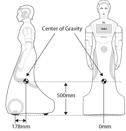
ARI has been designed to be statically stable, due to its low center of mass, fixed torso, and mass distribution with very lightweight arms. even when the arms are holding its maximum payload in its most extreme kinematic configuration. Nevertheless, some measures need to be respected in order to avoid the robot tipping over.
Measure 1
Do not apply external downward forces to the arms when they are extended.
Measure 2
ARI has been designed to navigate in flat floor conditions. Do not navigate on floors with unevenness higher than 5%.
Measure 3
Avoid navigating close to downward stairs, as ARI’s RGB-D camera will not detect this situation and the robot may fall down the stairs.
3.1.5 Measures to prevent collisions
Most collisions occur when moving ARI’s arm. It is important to take the following measures into account in order to minimize the risk of collisions.
3.1.6 Battery leakage
The battery is the only component of the robot that is able to leak. To avoid leakage of any substance from the battery, follow the instructions defined below, to ensure the battery is manipulated and used correctly.
The following guidelines must be respected when handling the robot in order to prevent damage to the robot’s internal batteries.
Do not expose the robot to fire.
Do not expose the robot to water or salt water, or allow the robot to get wet.
Do not open or modify the robot. Avoid, in all circumstances, opening the internal battery case.
Do not expose the robot to temperatures above 49◦C for over 24 hours.
Do not store the robot at temperatures below -5◦C for more than 7 days.
For long-term storage (more than 1 month) charge the battery to 50%.
Do not use ARI’s batteries for any other purpose.
Do not use any devices except the supplied charger to recharge the battery.
Do not drop the batteries.
If any damage or leakage is observed, stop using the battery.
3.2 Robot Identification (label)
The robot is identified by a physical label. This label contains:
Business name and full address.
Designation of the machine.
Part Number (P.N.).
Year of construction.
Serial number (S.N.).
4 Getting started with ARI
4.1 Unboxing ARI
ARI comes with a Quick Start guide. Below are the instructions from the Quick Start guide on how to unbox the robot:
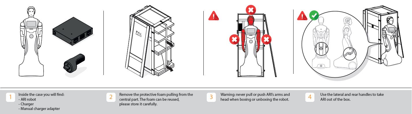
Inside the case you will find: ARI robot, charger, manual charger adapter
Remove the protective foam, pulling from the central part. The foam can be reused, please store it carefully.
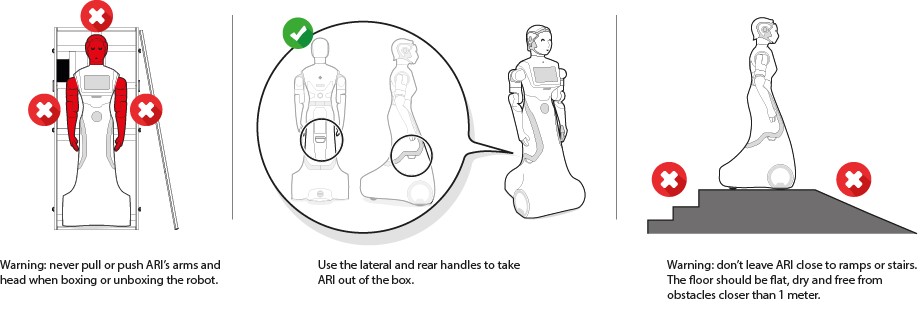
Warning: never pull or push ARI’s arms and head when boxing or unboxing the robot.
Use the lateral and rear handles to take ARI out of the box.
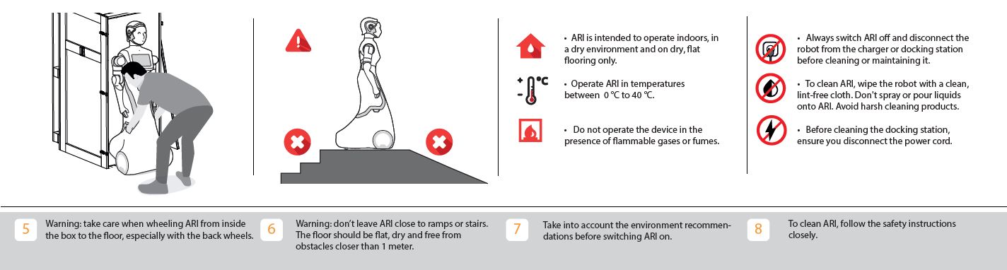
Warning: take care when wheeling ARI from inside the box to the floor, especially with the back wheels.
Warning; don’t leave ARI close to ramps or stairs. The floor should be flat, dry and free from obstacles closer than 1 meter.
Take into account the environment recommendations before switching ARI on.
To clean ARI, follow the safety instructions closely.
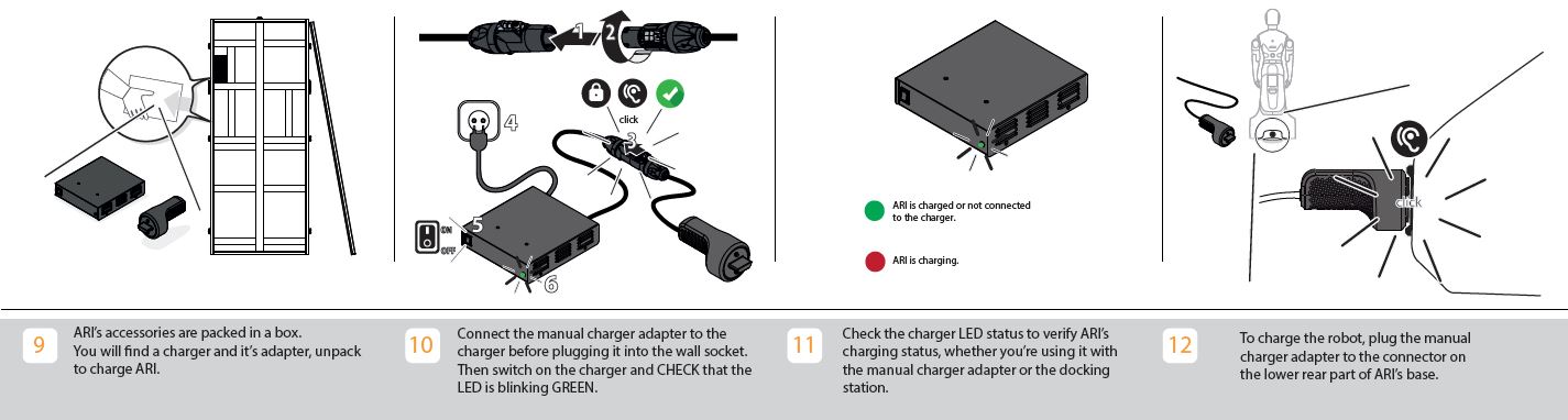
ARI’s accessories are packed in a box. You will find a charger and its adapter, unpack to charge ARI.
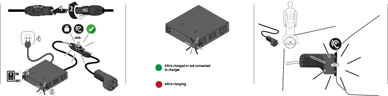
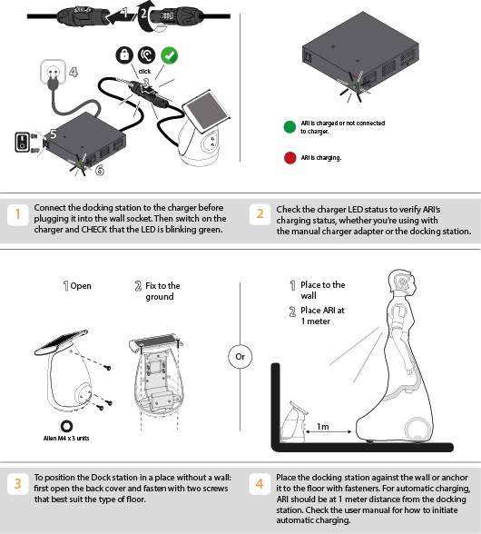
Connect the manual charger adapter to the charger before plugging it into the wall. Then switch on the charger and CHECk that that the LED is blinking green.
Check the charger LED status to verify ARI’s charging status, whether you’re using the manual charger adapter or the docking station.
To charge the robot, plug the manual charger adapter to the connector on the lower rear part of ARI’s base.
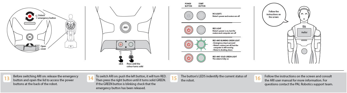
Before switching ARI on: release the emergency button and open the lid to access the power buttons at the back of the robot.
To switch ARI on: push the left button, it will turn RED. Then press the right button until it turns solid GREEN. If the GREEN button is blinking check that the emergency button has been released.
Follow the instructions on the screen for more information. For questions contact the PAL Robotics support team.
There is an available QR code for access to the ARI user manual.
4.1.1 What’s in the box
The ARI box will contain the following items:
ARI Robot
Battery Charger and Charger Adapter
USB flash drive with installation software
Docking station (optional)
NVIDIA Jetson (optional)
4.2 Power management
4.2.1 Emergency stop
When Emergency Stop is pushed, motors are stopped and disconnected. The green indicator of the ON/OFF button will blink fast in order to notify the user of the emergency state.
To start normal behaviour again, a two step validation process must be executed: the emergency button must be released by rotating clockwise, and then the ON/OFF button must be pressed for one second. The green light indicator of the ON/OFF button will change to a fixed state.
4.2.2 Charging the robot’s battery
Overview
Depending on the version acquired, your ARI may include a docking station that allows the robot to recharge itself automatically. This section will describe the components of the docking station and how to integrate it with your algorithms.
4.2.3 Charging ARI with cable charger
ARI must only be charged with the provided charger and adapter.
First you need to connect the manual adapter to the charger. Then it should be plugged into the wall socket. To charge the robot, plug the manual charger adapter to the connector on the lower rear part of ARI’s base. Then switch ON the charger and CHECK that the LED indicator is blinking GREEN if the robot is fully charged or NOT connected to the charger. The LED indicator should be RED when ARI is charging.
4.2.4 Charging ARI with dock station
The docking station hardware and installation
Figure below indicates the components of the docking station.
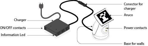
The dock station itself is composed of an adapter, where there are buttons to switch it on and off, charger and a LED indicating whether the robot is charging or not. The other end contains a base, that should be supported against a wall, power contacts, to establish contact with the robot, and an ARUCo marker, which is what the robot detects in order to dock.
The docking station should be preferably mounted against a hard surface, to avoid the robot displacing it while doing a docking manoeuvre. The power charger must be plugged into the respective plug. The user must also assure that no objects are present in the docking station surroundings, that could interfere with the docking manoeuvre.
Docking algorithm
In order to carry out autonomous docking the robot uses its back stereo-fisheye camera, located right below the emergency button, in order to detect the ARUCo marker.
When the robot is asked to go to the dock station, it activates two services in parallel. The first is responsible for the pattern detection, while the second performs the serving to reach the power contacts:
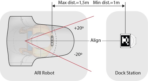
Pattern detector: the robot is capable of detecting the pattern up to 1-1.5 meters from the torso back RGB-D camera and with an orientation angle of 40º
Servoing manoeuvre: it comprises two steps, where first the robot aligns itself with the power contacts and, secondly, moves backwards advances until the contact is made or a timeout occurs (in the case the docking station is not powered, or the contact falls for example).
In order to initiate the docking the robot should be between 1 and 1.5 m away from the dock station. It is also an option to define a point of interest in order to pre-position the robot more easily.
Once the robot is docked, it will block most velocity commands sent to the base, in order to avoid manoeuvres that could possibly damage the robot or the dock station. There are only two ways of moving the robot after it is docked: By doing an undock manoeuvre, or using the graphical joystick, which can override all velocity commands.
WARNING: it is the sole responsibility of the user to operate the robot safely with the joystick after the robot has reached the docking station.
Usage
The docking/undocking manoeuvres are available through two different action servers that can be activated by using the provided rviz plugin or directly through the action server interface.
4.2.5 Dock/Undock through WebGUI
In order to dock/undock using the WebGUI first log in (username and password: pal).
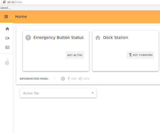
Once logged in navigate to the Surveillance tool (camera icon).
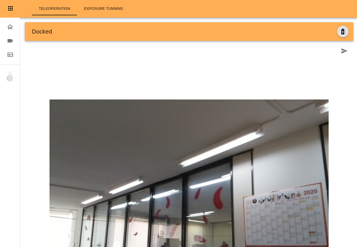
On the Surveillance plugin the top bar shows the current state of the robot (Docked or Undocked), the icon on the left permits undocking if the robot is docked, or Dock if the robot is undocked and in front of a docking station.
See 10 WebGUI for further information.
4.2.6 Dock/Undock using RVIz plugins
A dock/undock panel is available as an RViz plugin, that can be added to any RViz configuration by going to the Menu Panels -> Add New Panel and then choosing the DockUndock Panel. It is also loaded through the robot’s preconfigured navigation RViz file.
export ROS_MASTER_URI= http://ari-0c:11311
rosrun rviz rviz -d `rospack find ari_2dnav`/config/rviz/navigation.rviz
The panel appears on the right lower side of this interface.
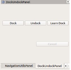
Once the user has positioned the robot within the tolerances specified before, he/she can click the Dock button to perform a docking manoeuvre. At any moment it is possible to cancel the docking manoeuvre by clicking the Cancel button. In a similar way, the robot can be moved out from the dock by clicking the Undock button. A status message will be shown beside the Cancel button, informing the user about the status of the action requested.
Please note: the robot will only accept an undock order if it was previously docked, otherwise the action request will be rejected.
It is also possible to use the Learn Dock button to have the robot learn the position of a new dock station and add it as a POIs in the given map. For this it is necessary that a map of the environment be previously built.
4.2.7 Dock/Undock using action client
ROS provides an action client interface that can be used to communicate with the action servers responsible for the dock and undock manoeuvres. To run the action client, the following command should be entered for the docking manoeuvre:
export ROS_MASTER_URI= http://ari-0c:11311
# For ROS Melodic
rosrun actionlib axclient.py /go_and_dock

# For ROS Noetic
rosrun actionlib_tools axclient.py /go_and_dock
and for the undocking manoeuvre:
export ROS_MASTER_URI= http://ari-0c:11311
# For ROS Melodic
rosrun actionlib axclient.py /undocker_server

# For ROS Noetic
rosrun actionlib_tools axclient.py /undocker_server
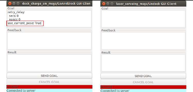
After any of the previous commands is executed, a panel will pop up. The figure below shows both the /go_and_dock and the /undocker_server panels.
Please note: for the docking action client, the field use_current_pose should be set to True, otherwise the action will fail (this field is not needed for the /undocker_server). In this interface, the button SEND GOAL would start the docking (or undocking) manoeuvre. As before, the CANCEL GOAL button will abort the action, and the status of the server and of the goal are displayed in the bottom of the panel.
4.2.8 Switching on/off ARI
On/off buttons
Electric switch The electric switch is the main power control switch. Before turning ARI ON make sure first that this switch is ON, i.e. its red light indicator is ON. On the other hand, when ARI is not going to be used for a long period, please press the switch so that its red light indicator turns OFF. Note that this switch should not be turned OFF before using the ON/OFF button to turn OFF the onboard computer of the robot. Turning OFF this switch will cut instantaneously the power supply to all the robot components, including the onboard computer. Do not use this switch as an emergency stop. For the emergency stop please refer to the next section.
Power Button and On/off button
Before switching ARI on: release the emergency button and open the lid to access the power buttons at the back of the robot.
5 First time startup
5.1 Switching on ARI
5.1.1 Welcoming Screen
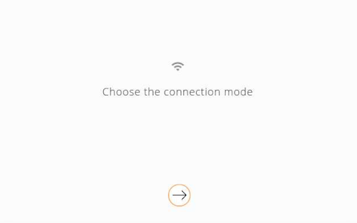
When switching on ARI for the first time, you will see the screen below. The setup process will take you through a number of screens to choose the connection mode, enter network details, choose a robot name, choose the language the robot will speak in and add a Master PIN.

5.1.2 First time Setup
During the setup process for the robot you will be asked to choose the WiFi connection mode, which can be either Access Point (AP) or Client Mode
5.1.3 Master/Admin PIN
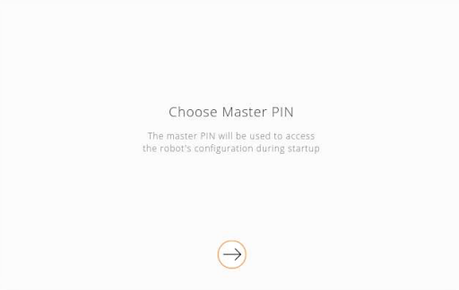
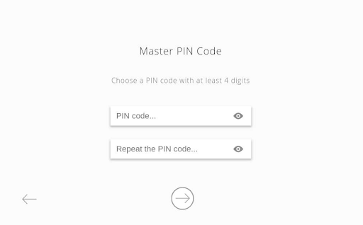
Select a Master PIN number for accessing ARI during the startup process. The Master PIN should be easy to remember and recorded somewhere else as it may be needed for future configuration. The PIN code should have at least four digits. You will be guided through the following screens:
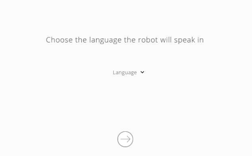
5.1.4 Language selection
ARI is programmed to speak in multiple languages, however only the languages installed on the robot will be shown. You will see the following screens to choose the language the robot will speak in:
5.1.5 WiFi setup
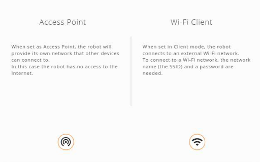
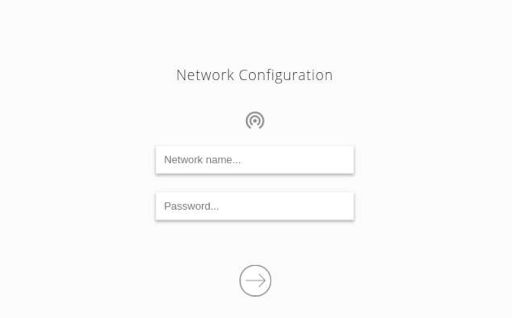
When the robot is set up as Access Point (AP) it provides its own network. You can then connect any WiFi-enabled device to the network (such as a laptop, tablet or phone). In the case of a device with mobile data capabilities being connected, it is necessary to ensure that those capabilities have been disabled to force the OS to use the WiFi network (both Android and iOS ignore WiFi with no internet connection, which prevents the device from accessing the WebGUI). Please note that in this mode the robot will not be able to connect to the internet.
When the robot is set to Client Mode the robot connects to an external WiFi network. In this mode the robot may be able to access the internet (if the network is connected to the internet), and will be visible to any and all devices in the same network.
Regardless of the chosen mode a network SSID and a password must be configured. If the robot is in AP mode this will be the name of the network provided by the robot, and the password required to connect to it. When in Client Mode this configuration will be used by the robot to connect to the external network.
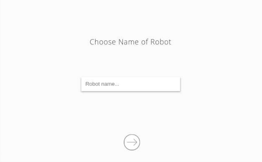
5.1.6 Robot Name
Finally, you will be prompted to choose a name for the robot with the following screen:
5.2 Connect from an external device
In order to connect to ARI with an external device, the device must be part of the same network:
If ARI is set up as Access Point the device must connect to the configured network using the password introduced during setup. ARI can then be accessed via the hostnames control or ari-Xc (where X is the serial number).
If ARI is set up as Client Mode, the device must be connected to the same network that was set up for ARI. ARI will then be accessible via the IP assigned by the network, or, if a DNS is set up, via the configured hostname.
In both cases, the WebGUI can be accessed using a web browser at the default port, and the Web Commander at port 8080 (see 10 WebGUI).
6 ARI’s autonomous navigation system
This section details ARI’s autonomous navigation framework. The navigation software uses Visual SLAM to perform mapping and localization using the RGB-D camera of the torso. This system works by detecting keypoints or features from the camera input and recognising previously seen locations in order to create a map and localize. The map obtained is represented as an Occupancy Grid Map (OGM) that can later be used to make the robot localize and navigate autonomously in the environment using move_base (http://wiki.ros.org/move_base)
6.1 Navigation architecture
The navigation software provided with ARI can be seen as a black box with the inputs and outputs shown in the figure below.
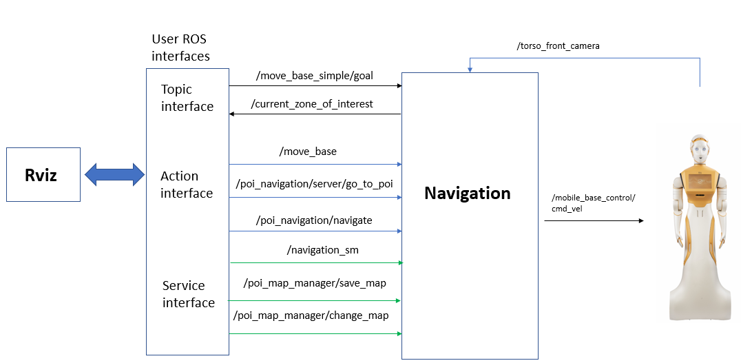
As can be seen, the user can communicate with the navigation software using ROS (Robotics Operating System: http://wiki.ros.org/) actions and services. Note that Rviz (http://wiki.ros.org/rviz) also can use these interfaces to help the user perform navigation tasks.
ROS nodes comprising the navigation architecture communicate using topics, actions and services, but also using parameters in the ROS param server.
6.1.1 Topic interfaces
/move_base_simple/goal (geometry_msgs/PoseStamped)
Topic interface to send the robot to a pose specified in /map metric coordinates. Use this interface if no monitoring of the navigation status is required.
/current_zone_of_interest (pal_zoi_detector/CurrentZoi)
Topic to print the name of the zone of interest where the robot is at present, if any.
6.1.2 Action interfaces
/move_base (move_base_msgs/MoveBaseAction)
Action to send the robot to a pose specified in /map metric coordinates. Use of this interface is recommended when the user wants to monitor the status of the action.
/poi_navigation_server/go_to_poi (pal_navigation_msgs/GoToPOIAction)
Action to send the robot to an existing Point Of Interest (hereafter POI) by providing its identifier. POIs can be set using Rviz Map Editor, see section SLAM and path planning on the robot.
/pal_waypoint/navigate (pal_waypoint_msgs/DoWaypointNavigationAction)
Action to make the robot visit all the POIs of a given group or subset. POIs and POI groups can be defined using the Rviz Map Editor, see section SLAM and path planning on the robot.
6.1.3 Service interfaces
/pal_navigation_sm (pal_navigation_msgs/Acknowledgment)
Service to set the navigation mode to mapping or to localization mode.
In order to set the mapping mode:
rosservice call /pal_navigation_sm "input: 'MAP'"
In order to set the robot in localization mode:
rosservice call /pal_navigation_sm "input: 'LOC'"
In the localization mode the robot is able to plan paths to any valid point on the map.
/pal_map_manager/save_map (pal_navigation_msgs/SaveMap)
Service to save the map with a given name. Example:
rosservice call /pal_map_manager/save_map "directory: 'my_office_map'"
The directory argument is the name of the map. If empty, a timestamp will be used. The maps are stored in $HOME/.pal/ari_maps/configurations.
/pal_map_manager/change_map (pal_navigation_msgs/Acknowledgment)
Service to choose the active map. Example:
rosservice call /pal_map_manager/change_map "input: 'my_office_map'"
6.2 Recap: WebCommander and DiagnosticsTab
The WebCommander is a web page hosted by ARI. It can be accessed from any modern web browser on a computer that is connected to ARI. It contains visualizations of the state of ARI’s hardware, applications and installed libraries, as well as tools to configure elements of its behaviour.
To access the WebCommander website
Ensure that the device you want to use to access the website is in the same network and able to connect to ARI
Open a web browser and type in the address bar the host name or IP address of ARI’s control computer and try to access port 8080:
If you are connected directly to ARI, when the robot is acting as an access point, you can also use:
6.2.1 WebCommander’s Diagnostics tab
Description: Displays the current status of ARI’s hardware and software
The color of the dot indicates the status of the application or component:
Green: no errors detected
Yellow: one or more anomalies were detected, but they are not critical
Red: one or more errors were detected which can affect the behaviour of the robot
Black: state, no information about the status is being provided.
The status of a particular category can be expanded by clicking on the “+” symbol on the left of the name of the category. Doing this will provide information specific to the device or functionality. If there’s an error, an error code will be shown.
6.3 SLAM and path planning on the robot
6.3.1 Pre-requirements and initial checks
In order to navigate with ARI the following components are needed:
Tablet/screen
Computer
ROS Melodic or PAL Ferrum installed
Robot
Joystick (if available)
Rviz
Before continuing with the instructions of this section make sure that the robot computer is able to resolve the development computer hostname. Otherwise, some commands will not work with the real robot due to communication failures between the robot’s computer and the development computer. We will assume that the development computer’s IP is 10.68.0.128, which will be set in the ROS_IP environmental variable. The user will have to adapt the examples below to set the right IP address.
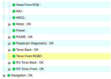
Note that when the robot is charging (either using the docking station or a cable), the Navigation functionality is paused for safety. The status of the functionality can be checked in the WebCommander diagnostics tab, see figure below. Alternatively, the status can be checked in /pause_navigation topic, which reports a boolean specifying whether the functionality is paused. Make also sure that no errors are visible in the diagnostics tab (no red indications) and that all are green.
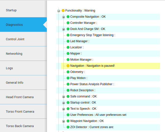
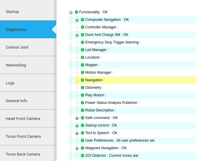
At the same time, make sure that the Torso Front Camera is publishing correctly, as it is the camera that will be used for navigation. For this you may check that in the Hardware section of the Diagnostics Tab the “RS Torso Front” appears green.
6.3.2 Booting the navigation system
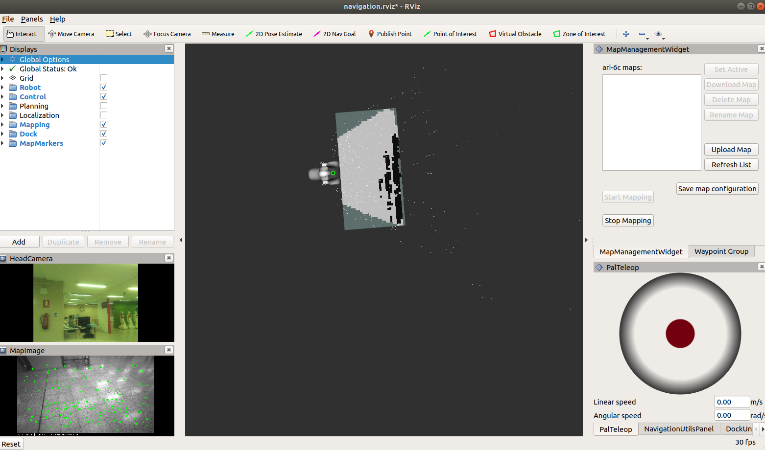
In order to visualise the mapping and localization pipeline using Rviz, ROS visual interface, from your development computer, the following command should be run in order to launch PAL’s Rviz Map Editor with a specific file for navigation, provided with ari_2dnav.
export ROS_MASTER_URI=http://ari-0c:11311
export ROS_IP=10.68.0.128
rosrun rviz rviz -d `rospack find ari_2dnav`/config/rviz/navigation.rviz
In order to ensure that rviz works properly, make sure that the robot computer is able to resolve the development computer hostname.
When the robot boots, the navigation pipeline starts automatically. Furthermore, the localization mode, using the last map, will be active.
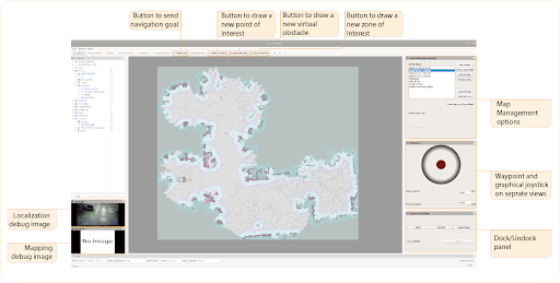
Through here it is possible to:
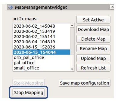
Start and stop mapping, by pressing the corresponding buttons in the MapManagementWidget, as well as perform other map operations, explained further in detail in Navigation Appendix A
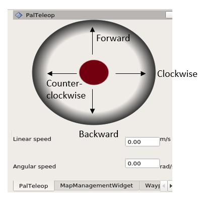
Move the robot around using the graphical joystick, on the PalTeleop tab, by guiding the red circle forward, backwards, or to the lateral sides in order to turn the robot clockwise/anti-clockwise
Generate POIs and execute a trajectory through them using the Waypoint Group tab
Dock / Undock the robot in order to charge it, using the DockUndock Panel
The upper horizontal bar contains a list of buttons to send:
navigation goal
create a POI
Virtual Obstacles
Zones of Interests
The left bar enables the user to visualize different components (e.g. mapping, localization, planning, the robot model), including the image outputs such as the keypoints detected through localization.
6.3.3 Creating a map
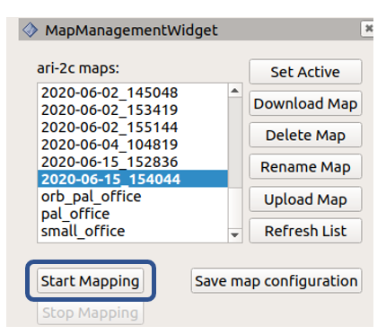
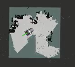
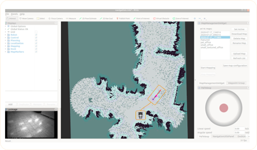
In order to create a new map focus on the right panel of Rviz, where the Stap/Stop Mapping buttons and the PAL Teleop joystick are displayed. Press the button Start Mapping to begin the mapping process.
The Rviz interface will change to that of the figure below.
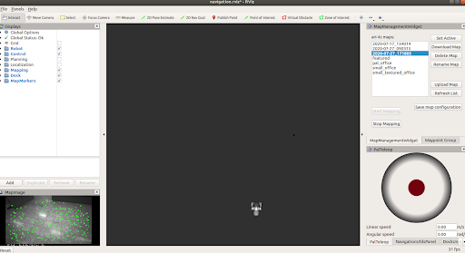
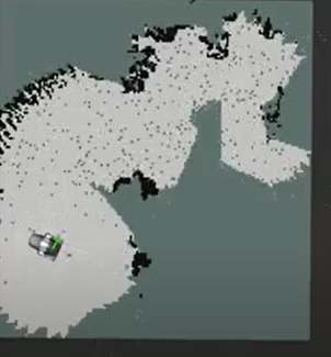
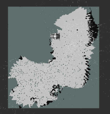
The robot base can be then tele-operated using the key_teleop package or the graphical joystick of Rviz by dragging and keeping the red button in the desired orientation, to move the robot forward or backwards, or to rotate it clockwise/counter-clockwise.
You will see the occupancy grid map updating as the robot moves.
Please make sure you can drive the robot safely before attempting to increase the speeds.
As you move the robot and it starts mapping, in order to make sure that the map is being done correctly, make sure that:
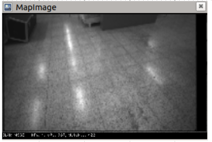
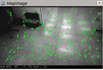
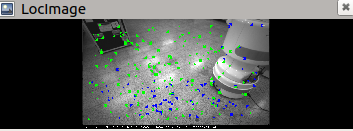
Green points are being detected in the MapImage interface. These are features or keypoints that the Visual SLAM algorithm detects through the torso RGB-D camera.
As the joystick is moved the robot should move accordingly in the map as its estimated pose is updated. It also serves to hint where it should go to continue mapping
To improve mapping process, it is recommended that you:
Move the robot slowly
Avoid sharp turns
Drive in circles in the same direction, by returning to a previous location so that the robot can recognise an already visited area to optimize the map.
Try to drive along walls and have objects in sight
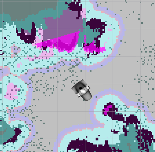
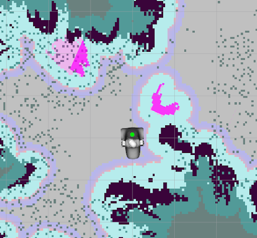
If at a given time key points disappear from the image, attempt to slow down the speed or return to the area where the robot was able to detect them previously. The figures below show a sample mapping process where the occupancy grid map is extended progressively.
Then it is time to “Stop Mapping”. This will create a new map on the robot with a name consisting of a time-stamp that can be used for localization and navigation. Bear in mind it may take a while to process and to store the map. For further details in where the mapping is stored refer to Navigation Appendix A.
At the same time, the robot will start using it for localization and path planning, once the “Start Mapping” option is activated again. If you would like to have more information on how to manage maps refer to Navigation Appendix A. Another option is to use a terminal window for the mapping process, which is detailed in Navigation Appendix B.
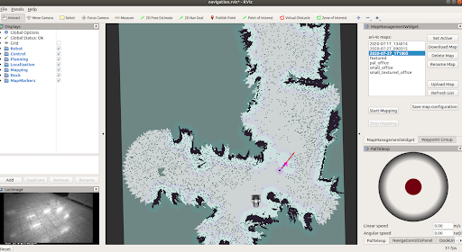
6.3.4 Localization
Once the “Start Mapping” option becomes available again the new map will be loaded and the robot will be localizing in it. You will see the occupancy grid map, as well as the localization debug image, that will output the keypoints detected through Visual SLAM and match them to the map built previously. .. image:: /manuals/ari/figures/ARI_navigation21.png .. image:: /manuals/ari/figures/ARI_navigation22.png
Note that in order to safely send navigation goals it is important to ensure the robot is well localised in the map, as otherwise the robot will not be able to reach the goal.
Because of this, before proceeding to path planning, ensure that the robot is well localized in the map:
The LocImage debug image on the left, which visualizes the output of the torso RGB-D camera, has some green key points in it, indicating that the localization system is recognising and matching features corresponding to the map built previously.
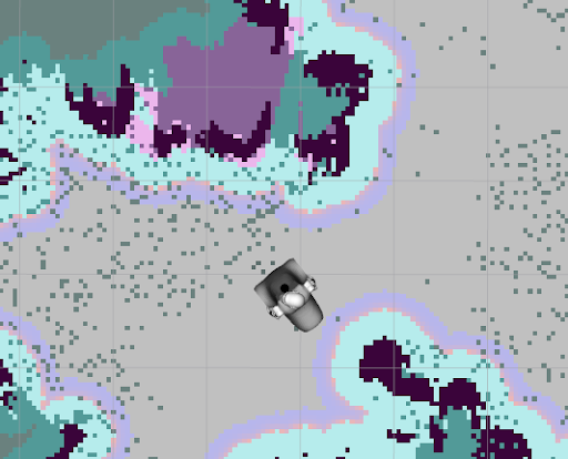
Costmaps are aligned, that is, that regions where obstacles should be are indicated properly.
Move_base node maintains two costmaps, one for the global planner and one for a local planner. They are visible in Rviz through the Planning section of the left panel:
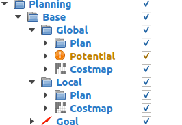
Global costmap: digital representation used by the global planner in order to compute paths to navigate from one point of the map to another without getting too close to the static obstacles registered during mapping. More details can be found here: http://wiki.ros.org/costmap_2d
Local costmap: similar to the global costmap, but it is smaller and moves with the robot, it is used to take into account new obstacles that were not present in the original map. It is used by the teb_local_planner to avoid obstacles, both static and dynamic, while trying to follow the global path computed by the global planner. More details can be found here: http://wiki.ros.org/costmap_2d.
As the robot is navigating, the costmaps should be updated accordingly, indicating the walls and obstacles at the expected locations.
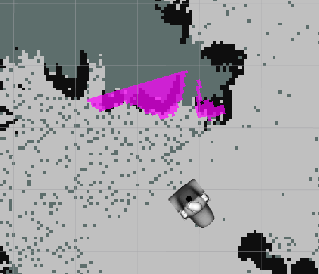
The figure below shows an example of the robot getting lost, as it is not detecting any keypoints through the image on the left bar and the robot is not in the right place in the map.
If no keypoints are detected and the costmaps do not appear aligned, the robot will rely on wheel odometry until it returns to a known area. Some reasons why this could happen are:
robot has moved to an area that is outside the generated map,
new objects have been added to the scene after producing the initial map
If the environment has not changed and the robot is within the mapped area, but the robot gets lost, attempt to return the robot towards the initial position or an area where it was previously localised.
6.3.5 Autonomous navigation
Once the robot has a map and is localized in it, we can send autonomous navigation instructions.
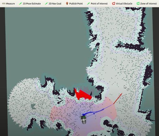
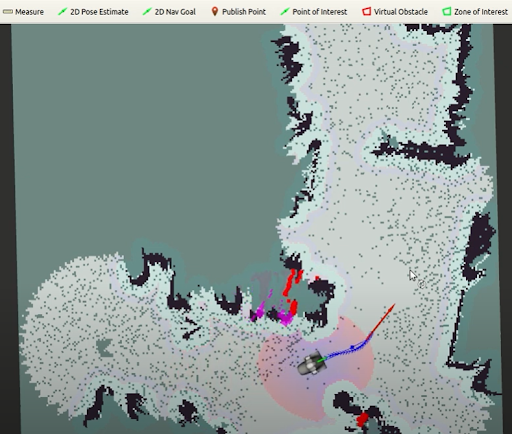
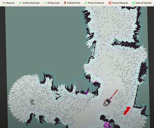
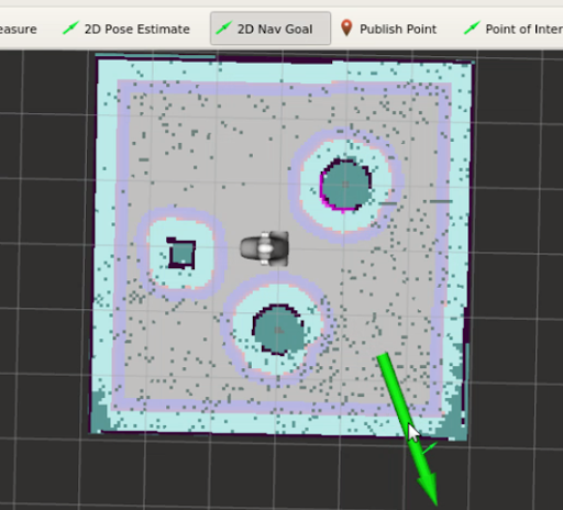
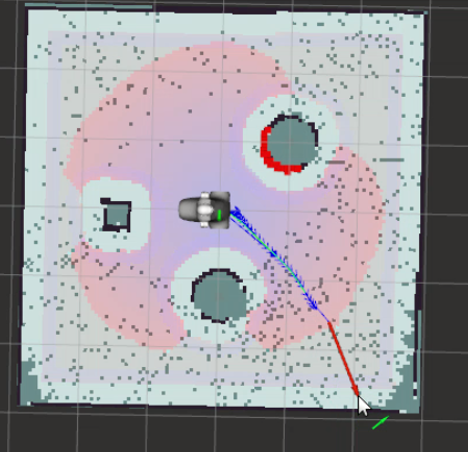
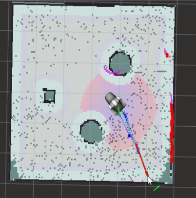
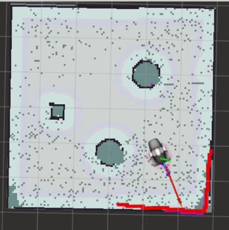
In order to perform autonomous navigation, click on the “2D Nav Goal” of the upper tool-bar, clicking on it with the left mouse button, and select the target location in the map that the robot has to reach while you drag towards the desired orientation.
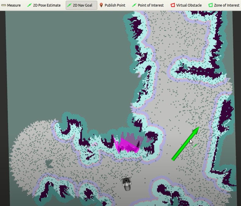
This will send the navigation goal to move_base, which will plan and execute the goal, as illustrated in the sequence of snapshots.
In the event that the robot does not move, make sure that the ROS_IP variable has been set with the right IP address of the development computer.
Navigation goals can be sent programmatically to the Action Server /move_base_simple.
6.4 SLAM and path planning in simulation
The procedure for the simulation is almost the same, instead of using a real robot it uses a Gazebo world and simulated ARI robot.
source /opt/pal/ferrum/setup.bash
roslaunch ari_2dnav_gazebo ari_navigation.launch
The Gazebo window shown in the figure below will open and the robot should be visible in a small enclosed environment.
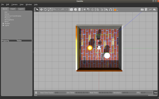
Furthermore, a Rviz window will open with the same content as with the real robot, loading the map of the simulation.
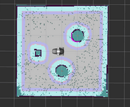
Using the graphical, or the teleop package, move the robot around taking considerations as with the real one in order to build the Point Cloud map after selecting Start Mapping in the MapManagementWidget. Once finished, select Stop Mapping, and an occupancy grid will be produced.
6.4.1 Localization and autonomous navigation
Executing the following on a terminal will start the simulation in localization and path planning mode.
roslaunch ari_2dnav_gazebo ari_navigation.launch
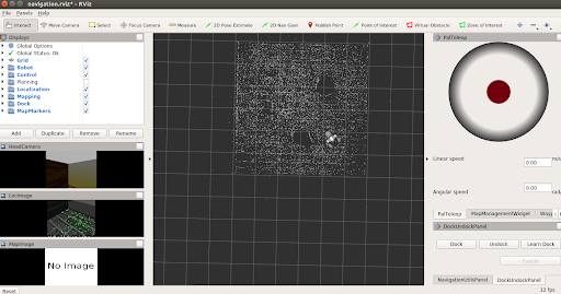
A Gazebo window will open, with the robot in a small enclosed environment, and will load the latest map created, indicating as well the localization debug image with detected keypoint and the localized robot model in the map.
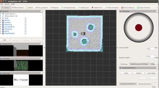
Ensure that the robot is well localized before sending navigation goals. The figure below shows a sequence:
6.5 Advanced Navigation utilities
This section covers additional functionalities of the Rviz panel that allow the user to define and execute a trajectory along points of interests, set-up zones of interests and edit the map to include virtual obstacles. The procedure for the simulation environment and the real robot is the same.
6.5.1 Defining Points of Interest
A Point of Interest is a pose in the map defined by a set of coordinates and orientation. Once a POI is defined and stored in the map metadata the robot can be sent to the POI using the go_to_poi action interface.
To create a new POI the button Point of Interest on the top bar of the Map Editor must be pressed.
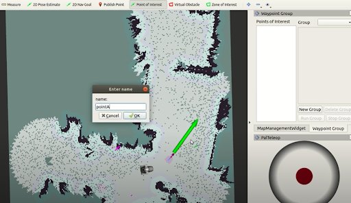
Then move the mouse to the desired map location, press the mouse’s left button and drag the mouse to define the orientation of the POI. Release the mouse’s button to create the POI. Afterwards, a dialog requesting the name of the POI will show up as shown in the figure below. After accepting it the POI will be created. In order to get these meta-data permanently stored press Save map configuration.
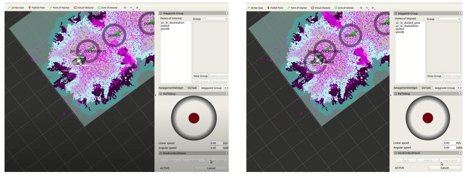
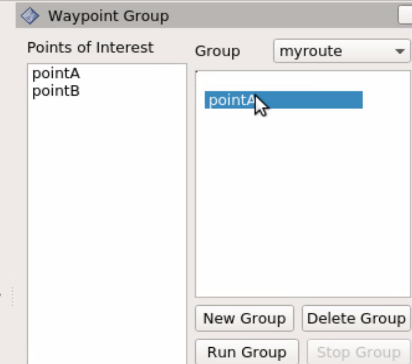
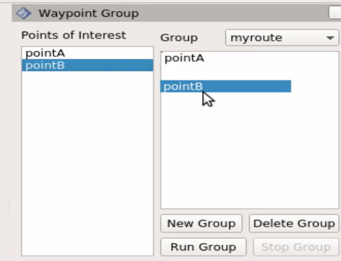
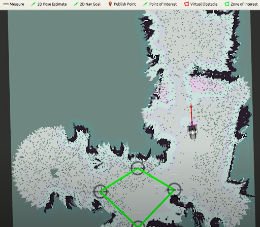
After creating POIs the user can define groups of POIs. By running a group of POIs, the robot will visit in sequence all the POIs in the group. To create groups of POIs the panel Waypoint Group is provided. The list on the left of the panel shows all the POIs created. First press New Group to define a new group of POIs. A dialog requesting the name of the group will appear, the figure below. In order to add POIs first select the POI on the left list and drag-and-drop it to the panel of its right. The same POI can be set multiple times. When the group contains all the desired POIs press the Save map configuration.
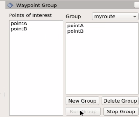
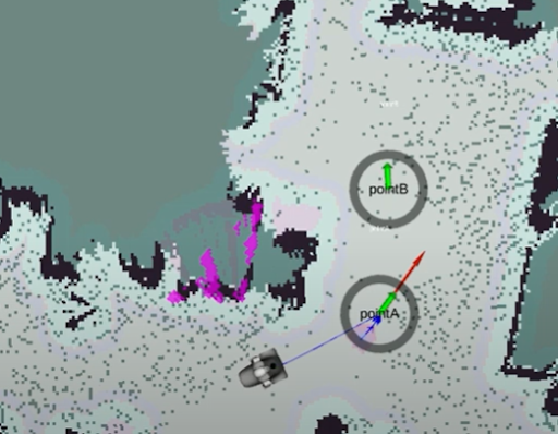
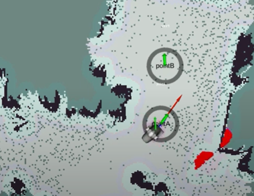
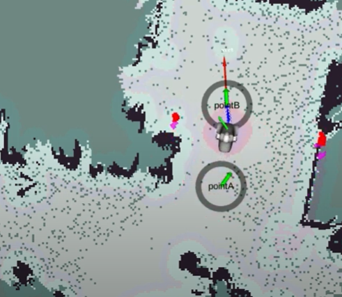
The robot will visit in sequence all the POIs in a group by selecting it in the dropdown list named Group and then pressing the Run Group. The task can be cancelled at any time by pressing the Stop group. The figure below shows the robot running a group of 2 POIs and avoiding VOs. In order to run a group of POIs the action interface /pal_waypoint/navigate is available.
6.5.2 Defining Zones of Interest
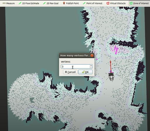
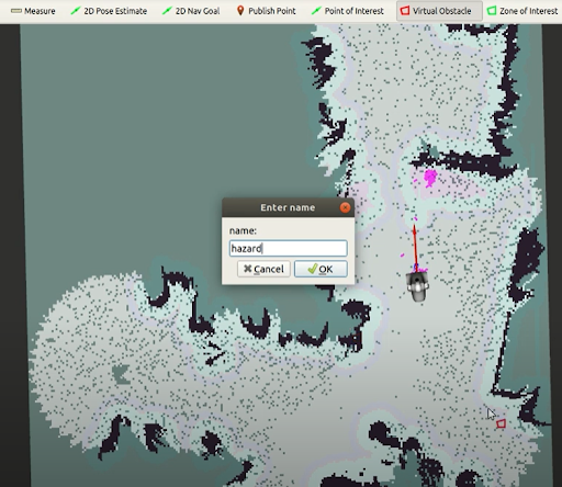
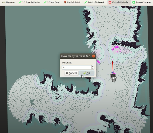
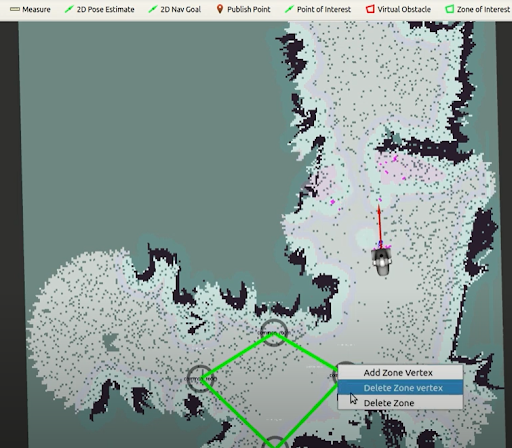
Zones of Interest provide a simple way to have topological localization, i.e. obtain the name of the zone of the map where the robot is located. A ZOI can be defined by pressing the Zone of Interest button on the top bar of the Map Editor. By clicking on a map point the user specifies the central position of the ZOI. Afterwards, a dialog requesting the name of the zone and then another requesting how many points will be used to define the zone will appear, see the figures below. A green polygon with the selected number of vertices will appear on the selection map point. The user can then drag the vertices with the mouse to define the final placement of the Zone of Interest. Note that in order to move a vertex of the zone the mouse icon must be placed on top of the blue circle, the color of the circle will vary slightly, before clicking on it and dragging it.

6.5.3 Defining Virtual Obstacles
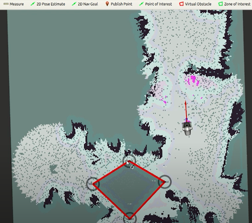
Virtual obstacles are of key importance to prevent some dangerous situations during navigation, like falling downstairs or colliding with obstacles not clearly visible for the robot’s sensors, and to label forbidden areas where the robot is not allowed to enter. The VOs are created the same way as the ZOIs by pressing the Virtual Obstacle button on the top bar of the Map Editor. VOs are represented with red polygons, see the figures below. In order to store the meta-data defining the VOs the user must press Save map configuration.
6.5.4 Modifying map meta-data
The POIs, ZOIs and VOs can be modified at any time or removed by placing the mouse icon on top of their blue circle and clicking on the right button. A popup menu will appear providing different options: removing the POI or in case of ZOIs and VOs adding a new vertex, removing a vertex or removing the whole ZOI or VO.
After any modification of the POIs, ZOIs or VOs remember to press Save map configuration to store the changes permanently in the map.
7 Sensors and joints
This section contains an overview of the sensors included in ARI, as well as their ROS and C++ API. Note that some cameras are optional.
7.1 Vision and inertial measurement unit sensors
The following Figure illustrates the cameras mounted on the robot.
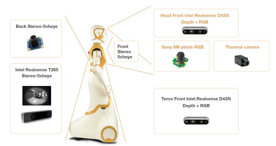
7.1.1 Torso front
Stereo RGB-D camera with IMU (Inertial Measurement Unit): This camera is mounted on the frontal side of the torso below the touch-screen and provides RGB images along with a depth image obtained by using an IR projector and an IR camera. The depth image is used to obtain a point cloud of the scene. It has an integrated IMU sensor unit mounted at the base to monitor inertial forces and provide the altitude.
7.1.2 Torso back
Stereo-fisheye camera with IMU (Inertial Measurement Unit): This camera is mounted on the back side of the torso, right below the emergency button, and provides stereo, fisheye and black and white images. It also has an IMU sensor unit.
7.1.3 Head cameras
Either one of these cameras, located inside ARI’s head, selected by the client.
RGB camera: provides RGB images
RGB-D camera: provides RGB-D images
7.1.4 Optional cameras
Frontal and back stereo-fisheye cameras: The frontal camera is positioned just above the touch-screen and the back camera, above the emergency button They publsh stereo images at 30 frames per second, and also publish IMU data.
Thermal camera: positioned below the head camera, inside the robot, to monitor temperature
7.2 LEDs
7.2.1 Back ring
ARI has an LED back ring at the back, below the emergency button, with a variety of colour options.
7.2.2 Ears rings
ARI has LED rings in each of its ears with a variety of colour options.
7.3 Animated eyes
ARI has LCD eyes with animations, supported by the movement of the head and arms, which can provide gaze interaction. Through gaze ARI can show interest - express emotions, and coordinate conversation by turn-taking and reacting to the user’s actions.
7.4 Speakers and microphones
ARI has an array of four microphones that can be used to record audio and process it in order to perform tasks like speech recognition located on the circlar gap of the torso. There are two HIFI full-range speakers just below it.
7.5 Joints
7.5.1 Base
The base joints of ARI are the front and back wheels of the robot. Take care when wheeling ARI, especially with the smaller back wheels.
7.5.2 Arms
ARI’s joints and arm movements are illustrated below:
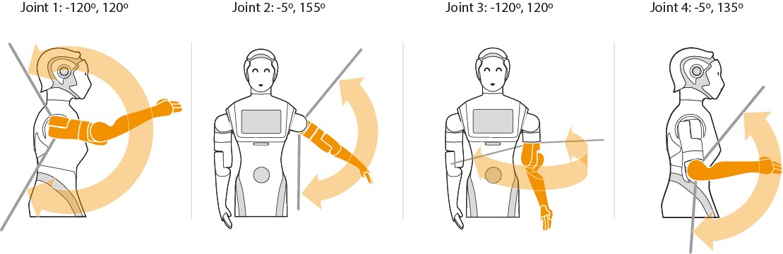
Joint 1: [-120º, 120º] Joint 2: [-5º, 155º] Joint 3: [-120º, 120º] Joint 4: [-5º, 135º]
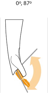
7.5.3 Hands
ARI’s hand movements are illustrated with the following diagram: [0º, 87º]
7.5.4 Head joints
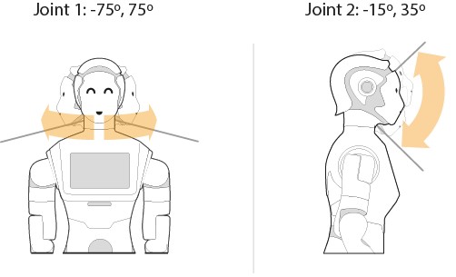
The joint movements for ARI’s head are shown below: Joint 1: [-75º, 75º] Joint 2: [-15º, 35º]
7.6 ROS API
The robot’s power status is reported in the /power_status ROS topic. Please note: This node is launched by default on startup.
Description
The following data is reported:
input: the voltage coming from the batteries.
charger: the voltage coming from the charger.
pc: the voltage coming from the PC.
charge: the percentage battery charge.
is_connected: whether ARI is currently connected to the charger.
is_emergency: whether the emergency stop button is currently enabled.
7.6.1 Sensors ROS API
Please note: Every node that publishes sensor data is launched by default on startup.
Inertial Measurement Unit:
Topics published
/torso_front_camera/accel/sample (sensor_msgs/Imu)
Inertial data from the IMU of the front camera
/torso_back_camera/accel/sample (sensor_msgs/Imu)
Inertial data from the IMU of the back camera
Torso front RGB-D camera topics:
/torso_front_camera/accel/sample (sensor_msgs/Imu)
Inertial data from the IMU of the front camera
/torso_front_camera/aligned_depth_to_color/camera_info (sensor_msgs/CameraInfo)
Intrinsics parameters of the aligned dept to color image
/torso_front_camera/aligned_depth_to_color/image_raw (sensor_msgs/Image)
Aligned depth to color image
/torso_front_camera/aligned_depth_to_infra1/camera_info (sensor_msgs/CameraInfo)
Intrinsics parameters of the aligned depth to infrared camera (aligned_depth_to_infra1 and aligned_depth_to_infra2)
/torso_front_camera/aligned_depth_to_infra1/image_raw (sensor_msgs/Image)
Aligned depth to infrared image
/torso_front_camera/color/camera_info (sensor_msgs/CameraInfo)
Camera calibration and metadata
/torso_front_camera/color/image_raw (sensor_msgs/Image)
Color rectified image. RGB format
/torso_front_camera/depth/camera_info (sensor_msgs/CameraInfo)
Camera calibration and metadata
/torso_front_camera/depth/color/points (sensor_msgs/Image)
Registered XYZRGB point cloud.
/torso_front_camera/depth/image_rect_raw (sensor_msgs/Image)
Rectified depth image
/torso_front_camera/infra1/camera_info (sensor_msgs/CameraInfo)
Camera calibration and metadata (infra1 and infra2)
/torso_front_camera/infra1/image_raw (sensor_msgs/Image)
Raw uint16 IR image
Torso front RGB-D camera services advertised
/torso_front_camera/rgb_camera/set_parameters (dynamic_reconfigure/Reconfigure)
Changes the specified parameters
Torso back RGB-D camera topics:
/torso_back_camera/accel/sample (sensor_msgs/Imu)
Inertial data from the IMU of the back camera
/torso_back_camera/fisheye1/camera_info
Camera calibration and metadata (fisheye1 and fisheye2)
/torso_back_camera/fisheye1/image_raw
Fisheye image (fisheye1 and fisheye2)
Head RGB topics:
/head_front_camera/camera_info (sensor_msgs/Image)
Intrinsics and distortion parameters of the RGB camera
/head_front_camera/image_raw (sensor_msgs/Image)
RGB image
Head RGB-D topics:
For the Head RGB-D camera, the following additional topics are available as well asides from the one for Head RGB:
/head_front_camera/accel/sample (sensor_msgs/Imu)
Inertial data from the IMU of the head RGB-D camera
/head_front_camera/aligned_depth_to_color/camera_info (sensor_msgs/CameraInfo)
Intrinsics parameters of the aligned dept to color image
/head_front_camera/aligned_depth_to_color/image_raw (sensor_msgs/Image)
Aligned depth to color image
/head_front_camera/aligned_depth_to_infra1/camera_info (sensor_msgs/CameraInfo)
Intrinsics parameters of the aligned depth to infrared camera (aligned_depth_to_infra1 and aligned_depth_to_infra2)
/head_front_camera/aligned_depth_to_infra1/image_raw (sensor_msgs/Image)
Aligned depth to infrared image
/head_front_camera/depth/camera_info (sensor_msgs/CameraInfo)
Camera calibration and metadata
/head_front_camera/depth/color/points (sensor_msgs/Image)
Registered XYZRGB point cloud.
/head_front_camera/depth/image_rect_raw (sensor_msgs/Image)
Rectified depth image
/head_front_camera/infra1/camera_info (sensor_msgs/CameraInfo)
Camera calibration and metadata (infra1 and infra2)
/head_front_camera/infra1/image_raw (sensor_msgs/Image)
Raw uint16 IR image
Optional stereo-fisheye camera topics:
/fisheye_rear_camera/rgb/image_raw/compressed (sensor_msgs/Image)
Fisheye image with IMU
/fisheye_front_camera/rgb/image_raw/compressed (sensor_msgs/Image)
Fisheye image with IMU
/fisheye_rear_camera/rgb/camera_info (sensor_msgs/CameraInfo)
Camera calibration and metadata
/fisheye_front_camera/rgb/camera_info (sensor_msgs/CameraInfo)
Camera calibration and metadata
7.6.2 Sensors visualization
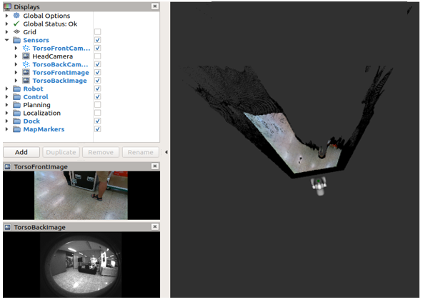
Most of the sensor readings of ARI can be visualized in rviz. In order to start the rviz GUI with a predefined configuration do as follows from the development computer:
export ROS_MASTER_URI=http://ari-0c:11311
rosrun rviz rviz -d `rospack find ari_bringup`/config/ari.rviz
An example of how the torso front and back RGB-D cameras are visualized in rviz.To be specific, the /torso_front_camera/depth/color/points topic output as well as the two images.
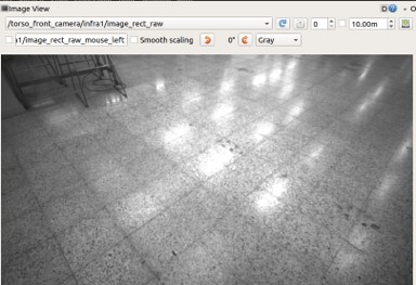
Another option is to visualize image output using the rqt GUI:
export ROS_MASTER=http://ari-0c:11311
rosrun image_view image_view image:=/torso_front_camera/infra1/image_rect_raw _image_transport:=compressed
When visualizing images from an external computer through WiFi, it is recommended to use the compressed topic to reduce bandwidth and latency.
7.6.3 Microphone sound recording
ARI has a ReSpeaker Mic Array V2.0 consisting of 4 microphones (https://www.seeedstudio.com/ReSpeaker-Mic-Array-v2-0.html).
In order to capture audio data, connect to the robot through ssh and list the available recording devices with the “arecord -l” command. You should see two soundcards that are detected on ARI:
ssh pal@ari-0c
arecord -l
Notice the name of the card and of the subdevice of the ReSpeaker device, and use that information to execute another arecord command.
arecord -fS16_LE -c6 -d 10 -r16000 > micro.wav
In this example we record 10 seconds of audio from the card 1, subdevice 0 into the micro.wav file.
To reproduce the recorded data the aplay command can be used.
aplay micro.wav
There are two main methods to access the microphone:
Using the ReSpeaker Python API (https://get-started-with-respeaker.readthedocs.io/en/latest/ReSpeakerPythonAPI/) to directly get microphone input.
Using the respeaker_ros open source ROS wrapper (https://github.com/furushchev/respeaker_ros). By default, the following launch file is running on the robot:
`` roslaunch respeaker_ros respeaker.launch``
It publishes the following topics of interest:
/sound_direction Result of DoA
/sound_localization Result of DoA as Pose
/is_speeching # Result of VAD
/audio # Raw audio > published as uint8 array
/speech_audio # Audio data while speeching
8 LED Control
This section contains an overview of the LED devices included in ARI and how to control them.
8.1 Overview
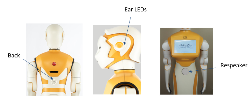
ARI has 4 led displaying devices capable of being controlled via our ROS interface. One at each ear, on in the back below the emergency stop and the respeaker leds.
ID |
#Leds |
Available Effects |
|
|---|---|---|---|
Back |
0 |
40 |
All |
Ear Left |
1 |
16 |
All |
Ear Right |
2 |
16 |
All |
Respeaker |
4 |
12 |
Fixed Color |
Different devices may have different capabilities, and may only be able to show part of the effects.
8.2 LED ROS Interface
All led devices are controlled using the same ROS Interface, provided by the PAL Led Manager. This interface allows clients to send effects to one or multiple led devices, for a duration of time and a priority. When a device has more than one effect active at a time, it displays the one with the highest priority, until the duration ends and then displays the next effect with the highest priority.
There’s a default effect with unlimited duration and lowest priority that display a fixed color.
The led interface is an Action Server with the name pal_led_manager/do_effect.
The type of the action is pal_device_msgs/DoTimedLedEffect
The fields are described in the .action and .msg files in the same repository.
As a summary, a goal consists of:
devices A list of devices the goal applies to.
params The effect type, and the parameters for the selected effect type.
effectDuration Duration of the effect, when the time is over the previous effect will be restored. 0 will make it display forever
priority Priority of the effect, 0 is no priority, 255 is max priority
9 WebCommander
9.1 Default network configuration
When shipped or when a fresh re-installation is performed, the robot is configured as an access point. Note that the SSID ends with the serial number of the robot, i.e. in the given example the s/n is 0.
The address range 10.68.0.0-24 has been reserved. The robot computer name is ARI-Xc, where X is the serial number without the “0s” on the left. The alias control is also defined in order to refer to the computer name of the robot when connecting to it when it is set as an access point or when using a direct connection, i.e. an Ethernet cable between the robot and the development computer.
The WebCommander is a web page hosted by ARI. It can be accessed from any modern web browser that is able to connect to ARI. It is an entry point for several monitoring and configuration tasks that require a Graphical User Interface (GUI).
9.2 Accessing the WebCommander website
Ensure that the device you want to use to access the website is in the same network and able to connect to ARI
Open a web browser and type in the address bar the hostname or IP address of ARI’s control computer and try to access port 8080: http://ARI-0c:8080
If you are connected directly to ARI, when the robot is acting as an access point, you can also use: http://control:8080
The WebCommander website contains visualizations of the state of ARI’s hardware, applications and installed libraries, as well as tools to configure elements of its behaviour.
9.3 Default tabs
ARI comes with a set of preprogrammed tabs that are described in this section, these tabs can also be modified and extended. Each tab is an instantiation of a web commander plugin. For each tab a description and the plugin type used to create it is defined.
Startup tab
Plugin:Startup
Description: Displays the list of PAL Robotics software that is configured to be started in the robot, and whether it has been started or not.
Each application, or group of applications, that provides a functionality, can choose to specify a startup dependency on other applications or groups of applications.
There are three possible states:
Green: All dependencies satisfied, application launched.
Yellow: One or more dependencies missing or in error state, but within reasonable time. Application not launched.
Red: One or more dependencies missing or in error state, and maximum wait time elapsed. Application not launched.
Additionally, there are two buttons on the right of each application. If the application is running, a “Stop” button is displayed, which will stop the application when pressed. If the application is stopped or has crashed, the button “Start” will be displayed, which will start the application when pressed. The “Show Log” button, allows to display the log of the application.
Startup extras tab
Plugin: Startup
Description: This tab is optional, if present it will contain a list of PAL Robotics’ software which is not started by default during the boot up of the robot. These are optional features that need to be manually executed by the user.
Diagnostics Tab
Plugin: Diagnostics
Description: Displays the current status of ARI’s hardware and software.
The data is organized in an hierarchical tree. The first level contains the hardware and functionality categories.
The functionalities are the software elements that run in ARI, such as vision or text to speech applications. Hardware diagnostics contain the hardware’s status, readings and possible errors. Inside the hardware and functionality categories, there’s an entry for each individual functionality or device. Some devices are grouped together (motors, sonars), but each device can still be seen in detail. The color of the dots indicates the status of the application or component.
Green: No errors detected.
Yellow: One or more anomalies detected, but they are not critical.
Red: One or more errors were detected which can affect the behavior of the robot.
Black: Stale, no information about the status is being provided.
The status of a particular category can be expanded by clicking on the “+” symbol to the left of the name of the category. This will provide information specific to the device or functionality. If there’s an error, an error code will be shown.
Logs Tab
Plugin: Logs
Description: Displays the latest messages printed by the applications’ logging system. The logs are grouped by severity levels, from high to low severity: Fatal, Error, Warn, Info and Debug. The logs are updated in real time, but messages printed before opening the tab can’t be displayed.
The log tab has different check-boxes to filter the severity of the messages that are displayed. Disabling a priority level will also disable all the levels below it, but they can be manually enabled. For instance, unchecking Error will also uncheck the Warn, Info and Debug levels, but the user can click on any of them to re-enable them.
General Info Tab
Plugin: General Info
Description: Displays the robot model, part number and serial number.
Installed Software Tab
Plugin: Installed Software
Description: Displays the list of all the software packages installed in both the robot’s computers
Settings Tab
Plugin: Settings
Description: The settings tab allows to change ARI’s behaviour.
Currently it allows to configure the language of ARI for speech synthesis. It is possible to select one from a drop down list. Changing the text-to-speech language will change the default language when sending sentences to be spoken by ARI.
Hardware Configuration
The Settings tab allows the user to configure the hardware of the robot. Hardware configuration will let the user to disable/enable the different motors, enable/disable the Arm module, choose different End Effector configuration, and also enable/disable the mounted F/T sensor.
For instance, to disable the “head_1_motor”, untick the head_1_motor checkbox in the “Enabled motors” options. If you want to switch to a different end-effector, then in the “End Effector” drop down, select the end effector that you are going to install, and click the “Save as Default” button at the bottom of the section. Reboot the robot for the above selected configuration to be taken into effect.
Remote Support
The Settings tab is equipped with the remote support connection widget. A technician from PAL Robotics can give remote assistance to the robot by connecting through this widget. Using an issue in the support portal, the PAL Robotics’ technician will provide the IP Address and the Port, this information needs to be filled in the respective fields of the widget and then pressing the Connect button will allow for the remote assistance. If the robot needs to be rebooted, the customer has to activate the remote support after each reboot because it is not persistent.
At any point of time after the connection has been established, the remote connection can be terminated by clicking the Disconnect button. Please note: After clicking the Connect, if the widget pops back to normal, instead of showing the connection status, then it means that the robot is either not connected to the internet (or) there should be some network issue.
Networking tab
By default, the controls for changing the configuration are not visible in order to avoid access by multiple users.
If the Enter button is pressed, the tab connects to the network configuration system and the controls will appear.
When a user connects to the configuration system, all the current clients are disconnected and a message is shown in the status line.
Configurations are separated in different blocks:
Wifi: – Mode: Can be selected whether WiFi connection works as client or access point.
SSID: ID of the Wi-Fi to connect to client mode or to publish in access point mode.
Channel: When the robot is in access point mode, use this channel.
Mode Key: Encryption of the connection. For more specific configurations select manual. In this case it is used the file /etc/wpa_supplicant.conf.manual that can be manually created in the robot.
Password: Password for the WiFi connection
Ethernet: – Mode: Can be selected whether the ethernet connection works as an internal LAN or external connection.
IPv4 – Enable DHCP Wifi: Enables DHCP client in WiFi interface.
Enable DHCP Ethernet: Enables DHCP client in the external ethernet port.
Address, Network, Gateway: In client mode, the manual values of the building’s network are used by the Wi-Fi interface. This is the same for the external ethernet port.
DNS
Server: DNS server.
Domain: Domain to use in the robot.
Search: Domain to use in the search.
VPN – Enable VPN: If the customer has a PAL basestation, the robot can be connected to the customer’s VPN.
Enable Firewall: When activating the VPN, a firewall can be connected to avoid an incoming connection from outside the VPN.
Address: Building network IP address of the basestation.
Port: Port of the base station where the VPN server is listening.
No changes are set until the Apply change button is pressed.
When the Save button is pressed (and confirmed), the current configuration is stored in the hard disk.
Be sure to have a correct networking configuration before saving it. A bad configuration can make it impossible to connect to the robot. If this happens, a general reinstallation is needed.
Changes to the WiFi between client and access point could require a reboot of the computer in order to be correctly applied.
Using the diagnostic tab, it is possible to see the current state of the WiFi connection.
Connecting ARI to a LAN In order to connect ARI to your own LAN follow the steps below.
First of all you need to access the WebCommander via the URL http://ARI-0c:8080 and go to the Networking tab. Press Enter button.
Once you have filled in the right configuration and pressed the Apply change button it is very important to wait until you are able to ping the new robot IP in your own LAN. If it does not happen you might have to reboot the robot as the configuration changes have not been saved yet. The robot will reboot with its previous networking configuration, allowing you to repeat the process properly.
When the new configuration allows you to detect the robot in your own LAN then you may proceed to enter the WebCommander again and press the Save button and then the Confirm button.
Setting ARI as an Access Point In order to configure ARI as an access point open the WebCommander via the URL http://ARI-0c:8080 and go to the Networking tab.
Once you have filled in the right configuration and pressed the Apply change button it is very important to wait until the new Wi-Fi network is detected. A smartphone, a tablet or a computer provided with a WiFi card can be used for this purpose. If it does not happen you might have to reboot the robot as the configuration changes have not been saved yet. The robot will reboot with its previous networking configuration, allowing you to repeat the process properly.
When the new configuration allows you to detect the robot’s Wi-Fi then you may proceed to enter the WebCommander after connecting to the Wi-Fi of the robot and press the Save button and then the Confirm button.
Video Tab
Plugin:Video
Movements Tab
Plugin: Movements
Description: Enables playing pre-recorded motions on ARI.
The movement tab allows a user to send upper body motion commands to the robot. Clicking on a motion will execute it immediately in the robot. Make sure the arms have enough room to move before sending a movement, to avoid possible collisions.
Demos tab
Plugin: Commands
Description: This tab provides buttons to start and stop different demos and synthesize voice messages with ARI, using either predefined buttons or by typing new messages in a text box.
9.4 Configuration
The WebCommander is a configurable container for different types of content, and the configuration is done through the /wt parameter in the ROS Parameter Server. On the robot’s startup, this parameter is loaded by reading all the configuration files in /home/pal/.pal/wt/. For a file to be loaded, it needs to have a .yaml extension containing valid YAML syntax describing ROS parameters within the /wt namespace.
In the box below, an example of how a WebCommander configuration is displayed. It is a YAML file, where /wt is a dictionary and each key in the dictionary creates a tab in the website with the key as the title of the tab. Each element of the dictionary must contain a type key, whose value indicates the type of plugin to load. Additionally, it can have a parameters key with the parameters that the selected plugin requires.
The parameters in the box of this section would create four tabs. Named “0. Startup”, “1. Diagnostics”, “2. Logs” and “3. Behaviour”, of the types Startup, Diagnostics, Logs and Commands respectively. The first three plugins do not require parameters, but the Command type does, as explained in the Command Plugin section.
Startup Plugin Configuration
Description: Displays the list of PAL Robotics’ software that is configured to be started in the robot, and whether it has been started or not.
Parameter format
Parameters startup_ids
A list of strings that contains the startup groups handled the instance of the plugin.
Diagnostics Plugin Configuration
Description: Displays the current status of ARI’s hardware and software.
Parameters: None required
Logs Plugin Configuration
Description: Displays the latest messages printed by the applications’ logging system.
JointCommander Plugin Configuration
Description: This tab provides slides to move each joint of ARI ’s upper body.
Parameters: A list of the joints groups to be controlled. Each element of the list must be a dictionary containing “name”, “command_topic” and “joints”. Where “name“ is the name that will be displayed for this group, “command_topic” is the topic where the joint commands will be published and “joints” is a list containing the joint names to be commanded.
General Info Plugin Configuration
Description: Displays the robot model, part number and serial number.
Parameters: None required
Installed Software Plugin Configuration
Description: Displays the list of all the software packages installed in both the robot’s computers.
Parameters: None required
Settings Plugin Configuration
Description: The settings tab allows you to change the behaviour of ARI.
Parameters: None required
Networking Embedded Plugin Configuration
Description: This tab allows you to change the network configuration.
Parameters: None required
Video Plugin Configuration
Description: Displays the images from a ROS topic in the WebCommander.
Parameters: topic Name of the topic to read images from, for instance: /xtion/rgb/image_raw/compressed
Movements Plugin Configuration
Description: Enables playing pre-recorded motions on ARI.
Parameters: goal_type Either “play_motion” or “motion_manager”. Determines which action server will be used for sending the motions.
Commands Plugin Configuration
Description:Contains buttons that can be programmed through parameters to perform actions in the robot.
Parameters buttons: A list of buttons, where each button is a dictionary with 2 fields. The name field is the text displayed on the button, and the second field name determines the type of button and is a dictionary with the configuration of the button.
9.5 Access Web Commander
IF the robot is AP: select ARI WIFI network and use the passw:”pal”. Then from the browser of the mobile device go to control:8080 or ari-SNc:8080
IF the robot uses external WIFI: from the browser connect to the address ari-assigned-ip:8080.
The WebCommander is a web page hosted by ARI. It can be accessed from any modern web browser that is able to connect to ARI.
It is an entry point for several monitoring and configuration tasks that require a Graphical User Interface (GUI).
Accessing the WebCommander website
Ensure that the device you want to use to access the website is in the same network and able to connect to ARI.
Open a web browser and type in the address bar the hostname or IP address of ARI’s control computer and try to access port 8080: http://ARI-0c:8080.
10 WebGUI
10.1 Overview
This section explains the use ARI’s Web User Interface and its different plugins. The Web User Interface is a tool designed to simplify the configuration of the robot as well as the user experience. The Web User Interface can be accessed via browser, at the address http://ari-Xc, where X is the serial number of the robot.
10.2 Technical considerations
At the moment the Web User Interface supports only the Chrome browser on a laptop or computer. Accessing the Web User Interface from a mobile phone or tablet, or from a different browser, will result in some of the functions not working properly or at all.
10.3 Login screen
When accessing the Web User Interface a user and password will be requested. The default user and password is pal / pal . Once the correct user and password are introduced the user will automatically be redirected to the page he was accessing.
Sessions are not time-constrained, which means that once a user has logged in he won’t be logged out until either he closes the browser or the robot is rebooted.
Figure: Login screen of the WebGUI.
10.4 Navigation between plugins
The menu on the left side contains the different plugins that are accessible for the user, depending on the configuration selected. Moving the mouse over the icons will show a tooltip to indicate the plugin name. Clicking on the menu icon on the top-left corner will open the menu, revealing both name and icon of the plugin. Clicking on an icon will redirect the user to the plugin.
Open navigation menu, with dark theme enabled.
The switch that can be found under the icons allows the user to change between light and dark themes for the WebGUI.
10.5 ARI Homepage
In this page there is a grouped list of webapps with short descriptions of each of them. Clicking on any icon will redirect you to the corresponding app:
Management - to configure the robot aspects (includes 10.7 Motion Builder, 10.8 Touchscreen Manager).
Monitorization - to access the robot status information (includes 10.6 Information Panel).
Teleoperation - to operate the robot remotely (includes 10.9 Command desks, 10.10 Teleoperation).
On top of the page there is a summary of the robot’s status in real-time. It indicates if the emergency button is pressed, if the robot is docked (if it’s charging now) and the level of the robot’s battery.
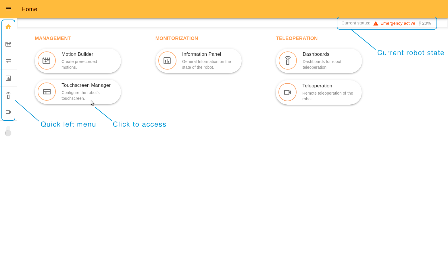
To quickly access any webapp use the menu on the left hand side. Under the menu icons there is a switcher between Light and Dark color themes.
10.6 Information Panel
The Information Panel serves to provide visual information on the robot’s current state.
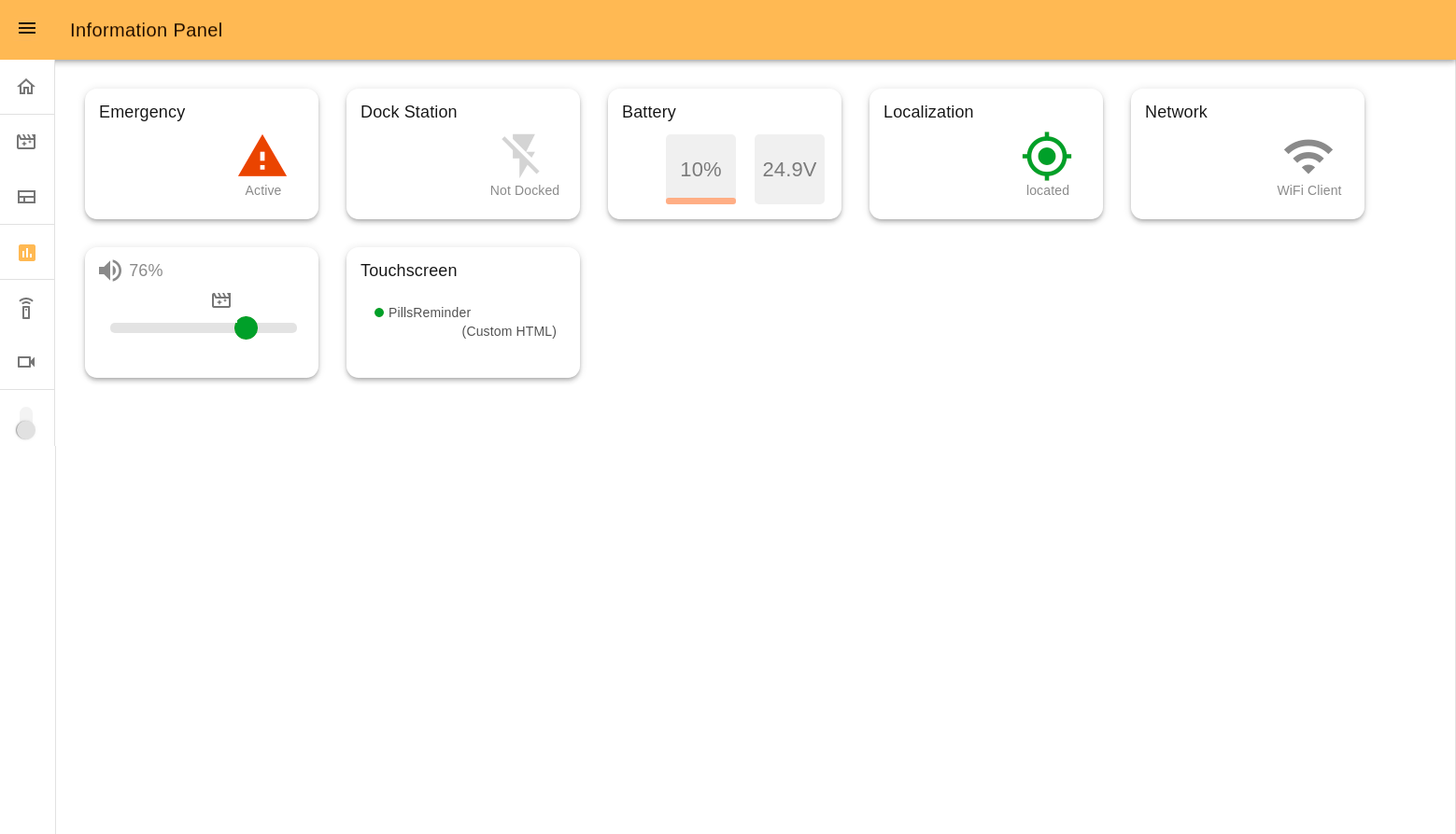
Emergency indicates the emergency button status (pressed or not). In the case of it being pressed, the icon will be red.
Dock Station indicates if the robot is connected to the dock or not.
Battery shows the current battery percentage and voltage. Yellow and red colors indicate middle and low battery levels.
Localization shows if the robot is located correctly in the navigation map.
Network indicates the currently active connection mode of the robot. Can be: Wi-fi Client or Access point.
Volume allows management of the robot’s volume and shows the current volume percentage.
Touchscreen is connected with the 10.8 Touchscreen Manager webapp. Here there is the information on the page that is displayed on the touchscreen and its template.
Some examples that may be displayed:
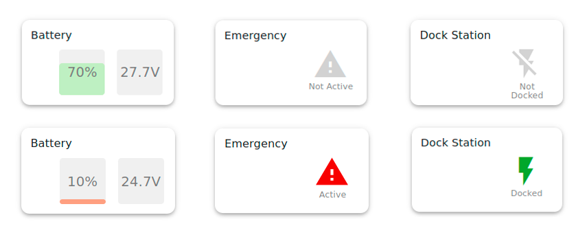
10.7 Motion Builder
The Motion Builder is a webapp that allows you to create prerecorded motions and execute them.
The features of Motion Builder tool include:
Creating, Editing, Deleting Motions
Adding, Editing and Deleting keyframes
Positioning the robot in any keyframe
Managing joints and groups used for the motion
Executing the motion at different speeds for testing purposes
Store the motion
The interface of Motion Builder consists of a list of the motions and a user-friendly editor, where you can create, edit and test motions without special technical skills.
10.7.1 Start page interface
The start page of Motion Builder serves not only to display stored motions but also to manage them. From here you can execute any motion, create copy and edit it, edit motion, delete it. Functions “Edit” and “Delete” are active only for motions created by the user.
Motions that have a star icon are default motions and can’t be edited or deleted. Click “Copy and edit icon” to use them as an example or a part of a new motion.
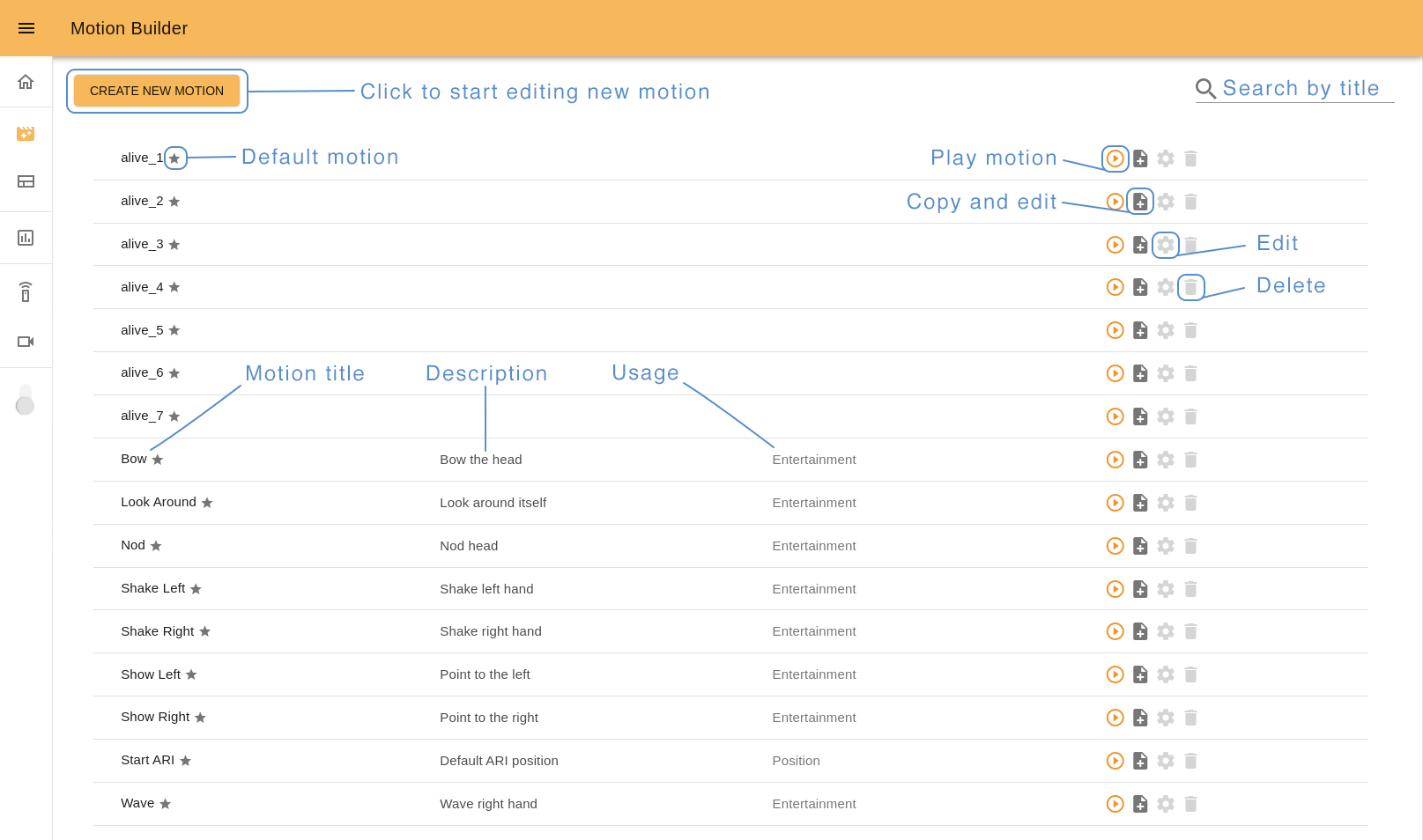
Use Search input (loupe icon) to browse the list easier. Start type the name of the motion you are looking for and you will see the corresponding results.
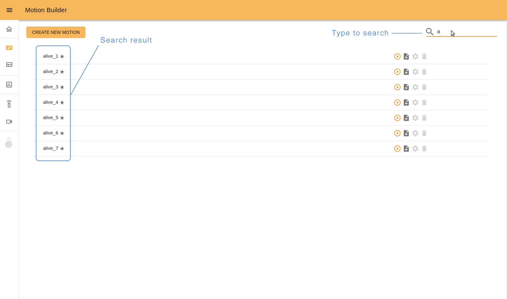
To open Motion Builder editor click “Create new motion” button, “Copy and edit” or “Edit” icons.
10.7.2 It’s important to know before starting
Each movement consists of a group of robot motors poses (keyframes) that the user has to define and capture.
The first you need to do is to position the robot in the desired keyframe. There are two ways to do it: by positioning the robot manually (Gravity compensation mode - optional package) or by using online Editor tools (Position mode).
In Gravity compensation mode the robot doesn’t have a motor control. You can freely fix the position of the robot’s motors (head, arms and hands) by moving them manually. In Position mode you can control the robot position by using the online tools: sliders and joystick. You can switch between different control modes instantly.
So to create a whole movement, capture the robot’s keyframes in the desired order.
10.7.3 Editor interface
Let’s see what the interface Motion Builder has and how to interact with it.
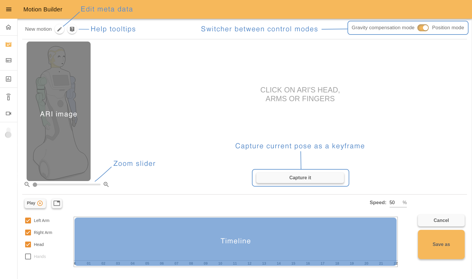
On the left top of the page there is a current motion name, “Edit meta” button and “Help mode” button.
10.7.4 Edit meta popup
Click the “Edit meta” button to set meta data of your motion: required ROS name, title, short description, and usage. This info is displayed on the Motion Builder start page (normally the ROS name is not shown but if a motion title wasn’t set previously, ROS name is used instead of it).
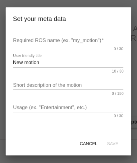
ROS name is a required field. It should be a unique word that describes the motions, starts with a letter and consists of the letters, numbers and _. It’s not allowed to change it after saving a new motion. Examples, “nod”, “shake_1”, “shake_2”, etc.
User friendly title should be a word or short phrase that helps you quickly understand what the motion does. It’s not a required field but it’s a good practise to fill it as well. Examples, “Nod”, “Shake Left”, “Shake Right”, etc.
In a short description field, you can describe some important details of the motion to distinguish it easily from the others. Examples, “Nod head”, “Shake right hand”, “Shake left hand”, etc.
In a usage field define the main usage of the motion. It is also a good practise to fill it because in the 10.9 Command desks webapp (“Motions” desk), you will see all your motions divided precisely by Usage names. Examples, “Entertainment”, “Greeting”, “Dance”, etc.
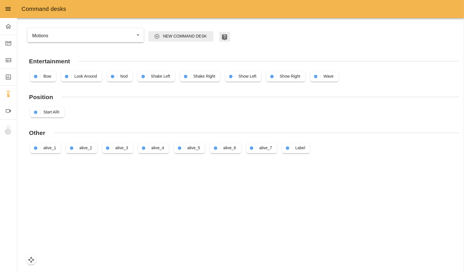
10.7.5 Help tooltips
“Help mode” button shows/hides help tooltips on the screen. If you click this button you will see blue icons with question signs. Hover the cursor over any icon to read a tip about Motion Builder usage.
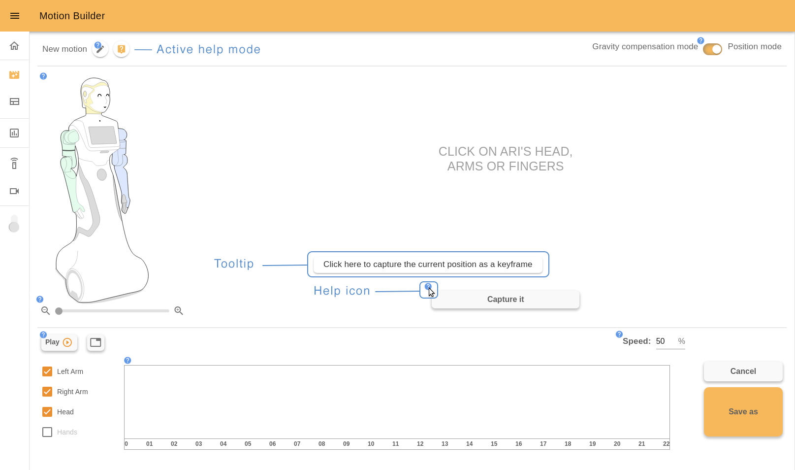
10.7.6 Position mode
On the right top of the page there is a switcher between different control modes. You can use it any moment during the editing process.
When the Position mode is active, you can interact with the ARI image and choose the part of the robot to control. Use a zoom slider under it to change the image size.
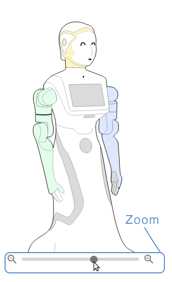
The painted parts are available to choose. For example, click ARI’s head to control it.
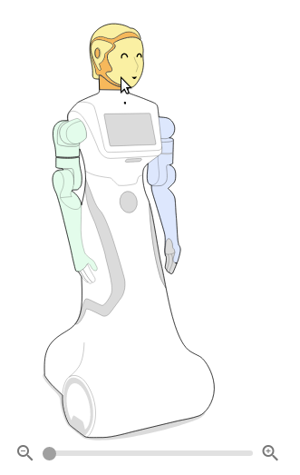
You also can manage joints and groups used for motion. Check the box with joints names on the bottom left of the page to add or remove it. In the example below we removed ARI’s head from the motion and now it’s not painted on the interactive image.
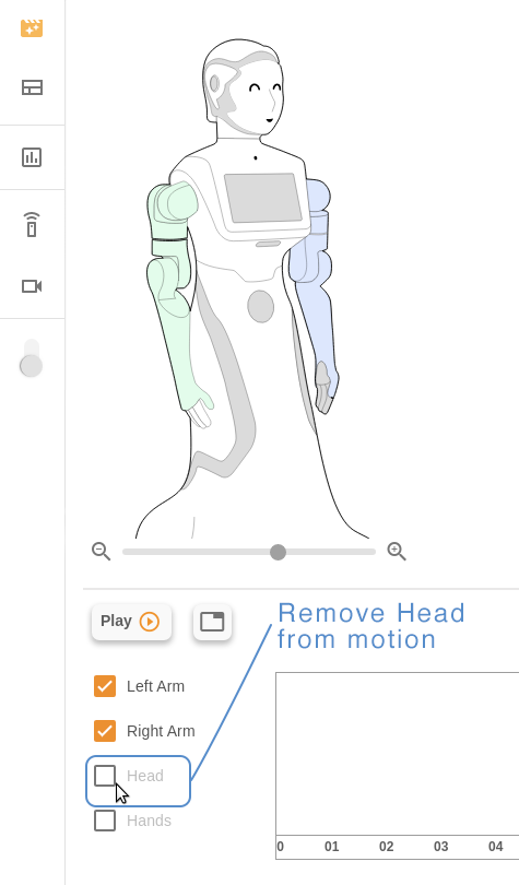
10.7.7 Joystick
To control ARI’s head use a joystick. Just drag the orange circle (green when the cursor is over it) and watch how the pose of the robot’s head changes.
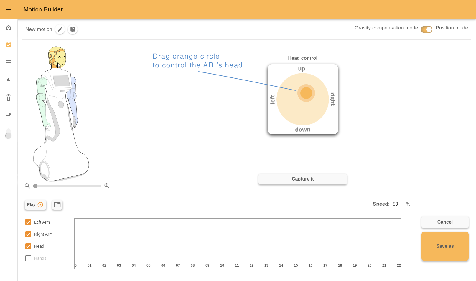
When you move a joystick quickly, for a short time it’s possible that the robot didn’t change its pose yet. In this case you will see a grey circle that shows the current pose of the head. When the robot has the same pose as the joystick, the grey circle will disappear.
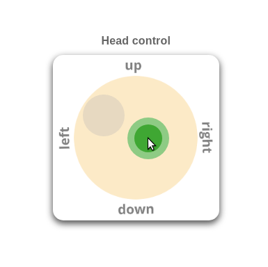
Click the “Capture it” button to store the keyframe.

10.7.8 Sliders
Sliders are used to control other groups of robots joints. Let’s click ARI’s arm.
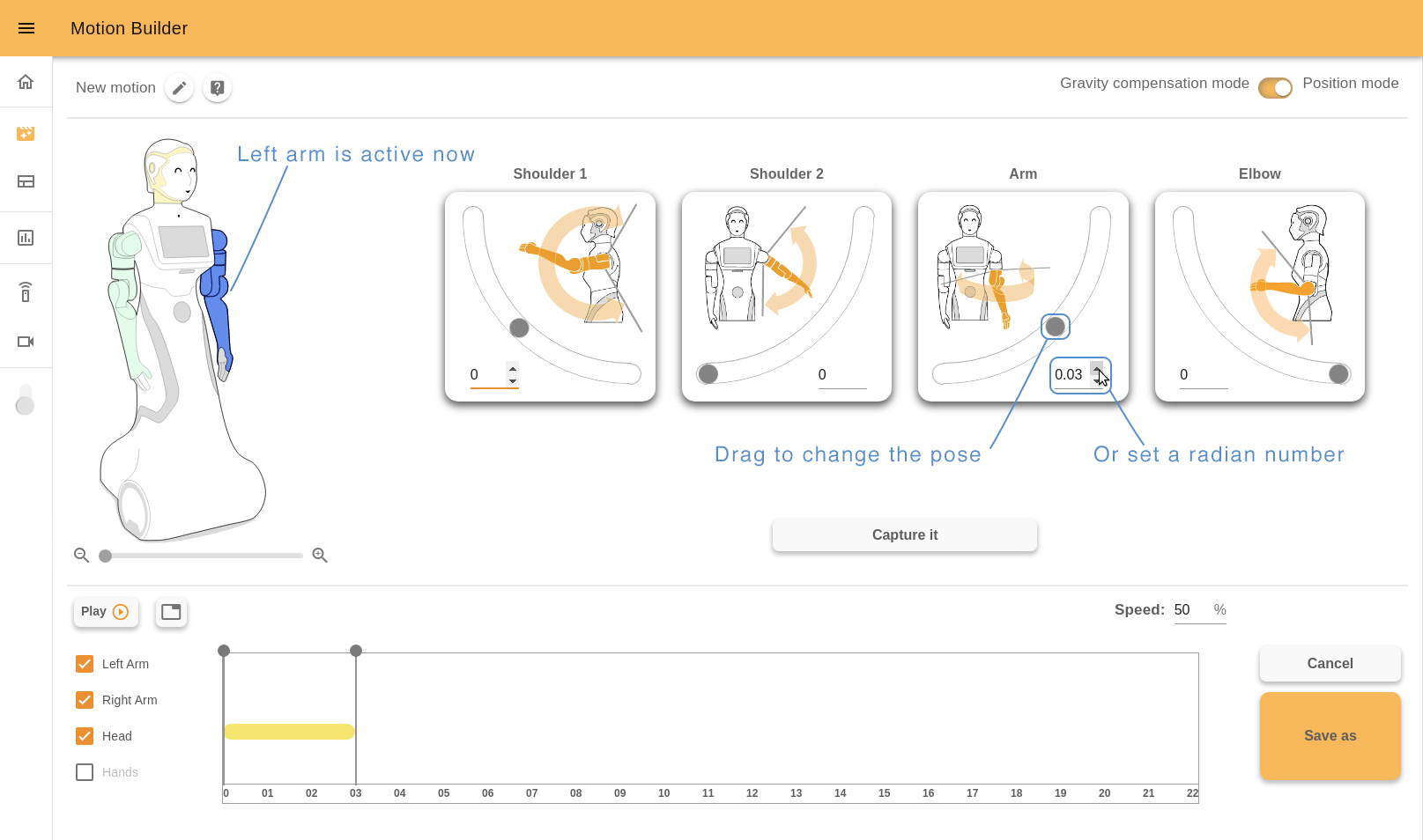
ARI’s arm consists of a group of joints. You can create complex motion by changing the joints pose by separate.
Each joint has a title and a description image. To control the joint, drag a slider circle or change the position number in the input field (type a desired number or use arrows).
Click the “Capture it” button to store the keyframe.
10.7.9 Gravity compensation mode (optional package)
When the Gravity compensation mode is chosen, ARI’s image will not be interactive. You should change the robot pose manually and click the “Capture it” button to store the keyframe.
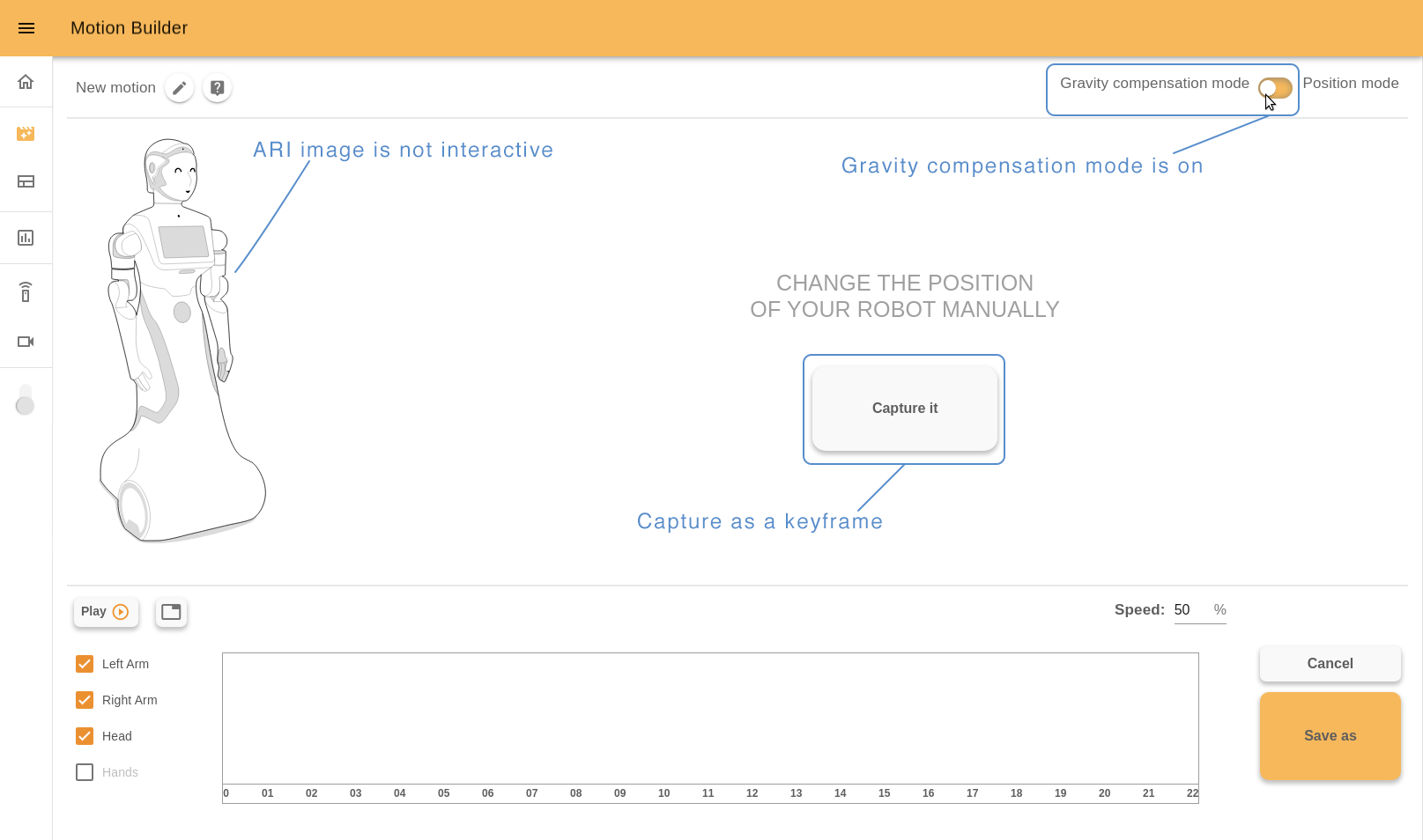
10.7.10 Timeline
After creating a new keyframe it will appear graphically on the timeline as a pointer. If the pose of any joints group was changed, opposite the corresponding checkbox will appear a colored line. The colors match with the color of the joints group on ARI’s image. For example, orange for the head, green for the right arm, blue for the left arm.
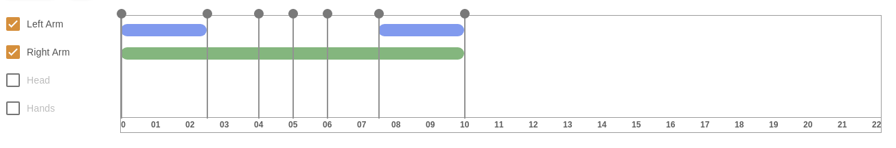
Each pointer is a keyframe you captured. It is situated on the timeline relatively to the time the robot needs to implement the motion. By dragging you can move the keyframe on the timeline.
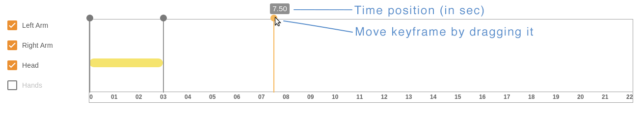
By double clicking you can open a context menu of the selected keyframe.
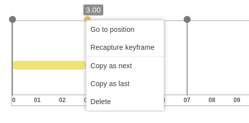
Go to position - robot will move to the captured position. Recapture keyframe - the selected keyframe will be replaced with the current pose of the robot. Copy as next - copy this keyframe right after it. Copy as last - add copy to the end of the motion. Delete - delete one keyframe.
10.7.11 InfoTable
The timeline has another view mode - infotable. Here you can see detailed info about each keyframe: how long this keyframe lasts (in seconds) and angular position of each joint in radians.
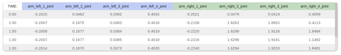
To change the view click a ‘table” icon near the “Play” button.
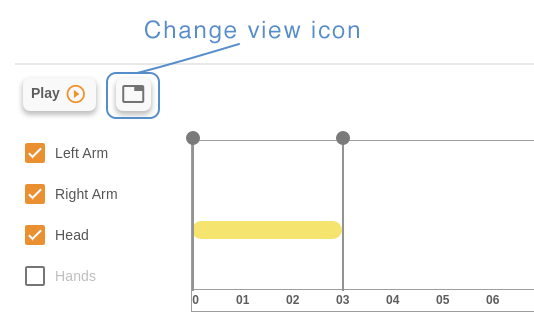
10.7.12 Speed of the execution
Speed number allows to control the speed of the motion execution. Switch to 100% to execute the motion at full speed, reduce it to slow down the motion.
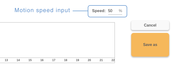
10.7.13 Play motion
You can play motion while editing or after it. To play motion from the Editor click the “Play” button under ARI’s image.
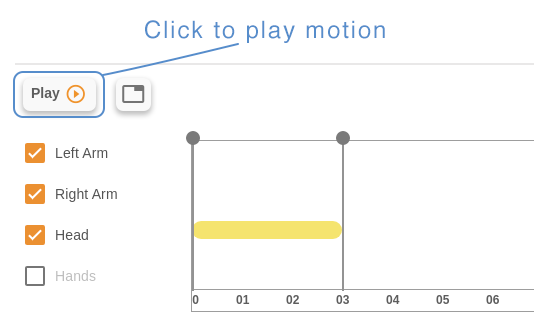
If you want to play the motion from the start page, click the “play” icon of the chosen motion.
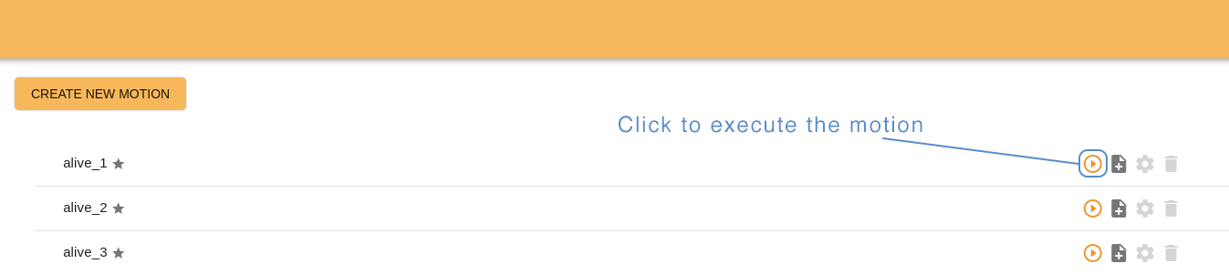
Also you can play motions from Command desks webapp. Open the “Motions” desk and click the corresponding button.
ARI’s touchscreen allows play motions as well. Create a page with buttons using “Page with buttons” or “Slideshow” template and assign any motion to the button on the screen. When a user touches this button, ARI will execute the motion.
10.7.14 Save motion
To leave the Editor without saving the changes click “CANCEL”, to store the changes and leave click “SAVE”. Remember that the ROS name is a required field. Fill it before saving a motion and leaving Editor.
10.8 Touchscreen Manager
The Touchscreen Manager is a webapp that allows you to create web pages and publish them on the ARI’s touchscreen.
The Touchscreen Manager consists of a list of the pages to display and an editor, where you can create pages using some predefined templates, or load your own HTML files.
From here, you can see all the pages that have been created, and you can edit them or delete them as well. To create a new page click on the “CREATE NEW PAGE ”button.
To make the page appear on ARI’s screen, click the publish button next to the page, and then it will be indicated with a green circle.
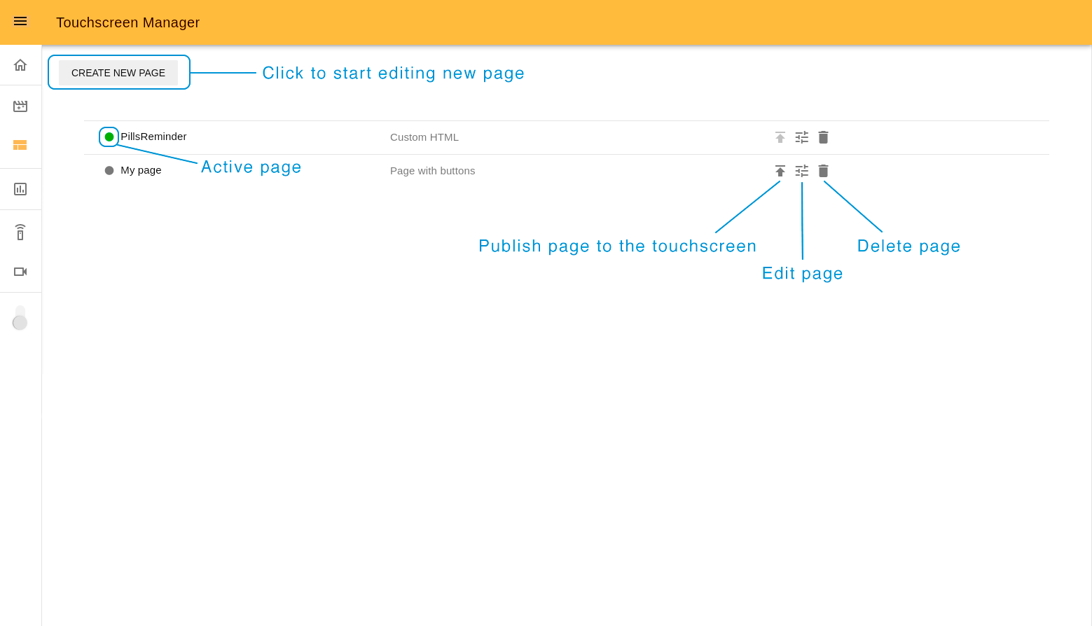
10.8.1 Create a new page
The Touchscreen editor is a tool that allows creating pages by customizing predefined templates or by importing your own webpage in .zip format. While the page is being edited a preview is displayed on the preview screen on the right.
Let’s check the full process for creating a new page.
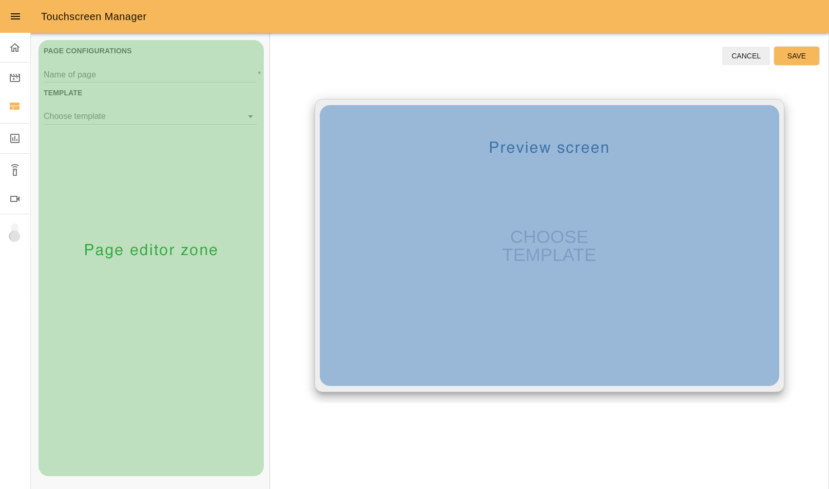
Step 1. Choose the page name. Remember it will be permanent and it is impossible to change it later.
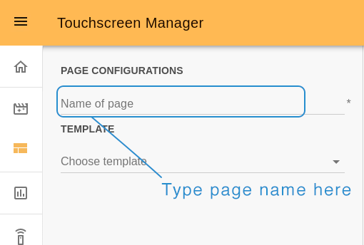
Step 2. Choose the template. There are three options: 10.8.2 Page with buttons, 10.8.3 Slideshow and 10.8.4 Custom HTML.
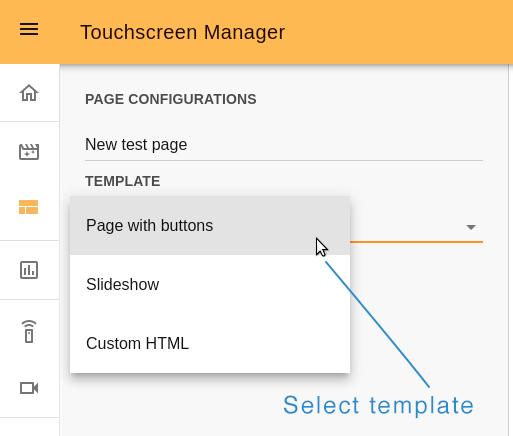
10.8.2 Page with buttons
The “page with buttons” template gives you the option of adding background images as well as custom buttons in different types of layouts.
Step 3. Set background. As a background you can choose any color or import your own image. The recommended image size is 1280x800px.
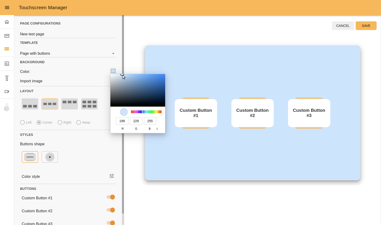
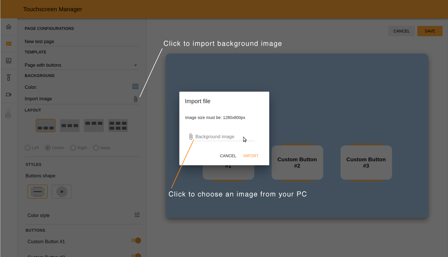
Step 4. Choose layout. In this section you can choose three possible positions for the buttons, add a second row of buttons, and align it (on the left hand side, center, right or away from each other if there are only two buttons in the row).
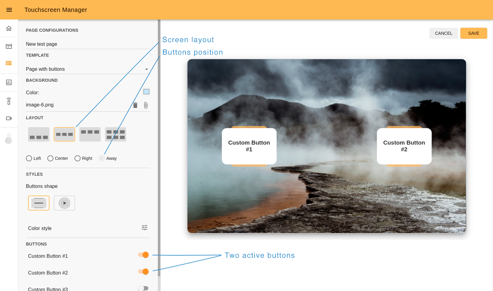
Step 5. Customize buttons. Touchscreen manager has two predefined designs of buttons: square and round. Some aspects can be customized. Here we can see how, by using the editor the button style changes. The Square button style allows you to change its colors and opacity.
You can customize the colors and opacity of the Round button style as well.
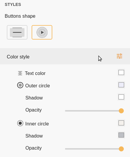
Under the “Color style” section there is a list of buttons you can display on the screen. The Switcher near the button name (by default is “Custom Button #N”) serves to show or hide this button on the screen.
The max quantity of buttons that can be shown on the screen is 6.
By clicking on the button name you will open an additional panel where you can change the button’s name, and choose an action for ARI to perform when the button is clicked. There are three options:
Motion- choose a motion for ARI from the list.Speech- type text for ARI to say.Change tablet's page- in case you want to be redirected to another page you created before.
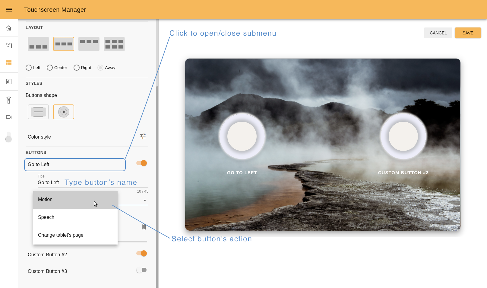
It’s not permitted to save a page if there are some buttons on the screen without any action assigned. Choose an action for each button you want to display on the touchscreen.
If you selected the Round button style in the previous step you will see the option to import the icon for each button. Make sure that the image has a transparent background and a small size. Suitable formats are PNG and SVG.
After import you can change the size of the uploaded icon.
In the case of choosing the “Slideshow” template these steps will be different.
10.8.3 Slideshow
With this template you can create a presentation of a series of still images. After choosing a page name and the Slideshow template the next step will be:
Step 3. Import photo. Click on the attach icon and one by one import photos to your presentation. In the same section you will see the list of imported photos. By dragging and dropping it is also possible to change the order in which the images will appear.
Step 4. Set preview settings. Choose how often the images will change. Also with the button “Play/Stop” you can check the results on the preview screen.
Importing at least one photo and setting a time period are mandatory steps before you can use the Play button.
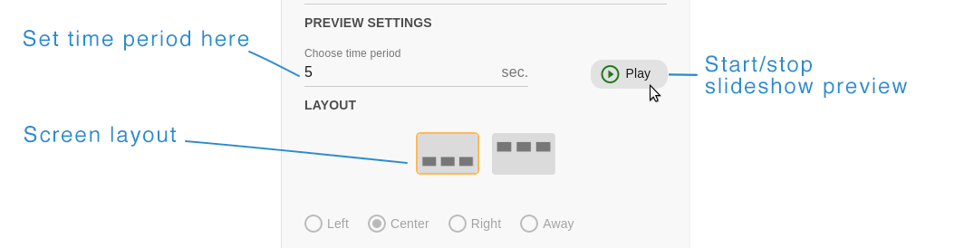
By clicking the Stop button you can put on pause a reproduction of slideshow preview.
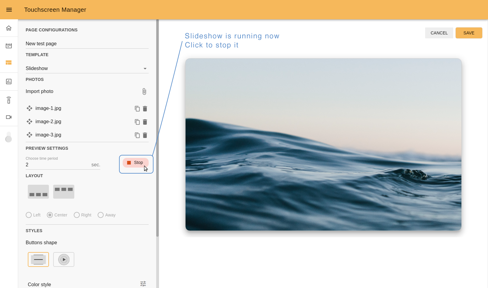
Step 5. Choose layout. The main difference between this section and the same one in the 10.8.2 Page with buttons template is the quantity of buttons that can be displayed. It’s possible to choose up to three static custom buttons that will be shown during the presentation. The buttons can be displayed on the top or on the bottom of the touchscreen, and can be aligned with each other (if you have less than three buttons in a row).
Step 6. Customize buttons. This step is identical to the one in the previous template: 10.8.2 Page with buttons, step 5.
10.8.4 Custom HTML
This template can be used if you want to display your own webpage. In the section File click the attach icon and import your file.
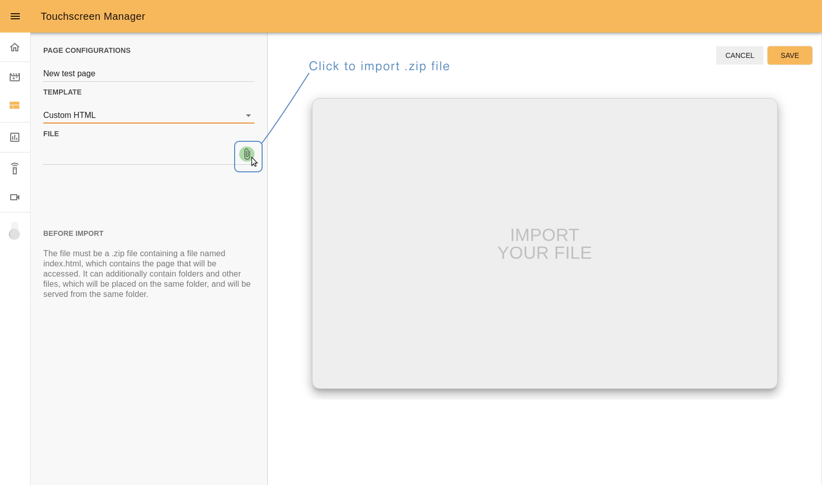
To display your webpage correctly:
the file must be a
.zipformat;the Zip file must contain a file named
index.html, which contains the page that will be accessed;it can additionally contain folders and other files, which will be placed in the same folder.
An example of how files can be organized before zip compression:
To check if you imported the file correctly, save the page, publish it, and view the result directly on ARI’s touchscreen.
10.8.5 Cancel or save
On the top right of the page there are the buttons “CANCEL” and “SAVE”. Click “CANCEL” if you want to stop editing and don’t want to save your progress. Click “SAVE” to save your page and go back to the pages list, where you can publish it on ARI’s touchscreen.
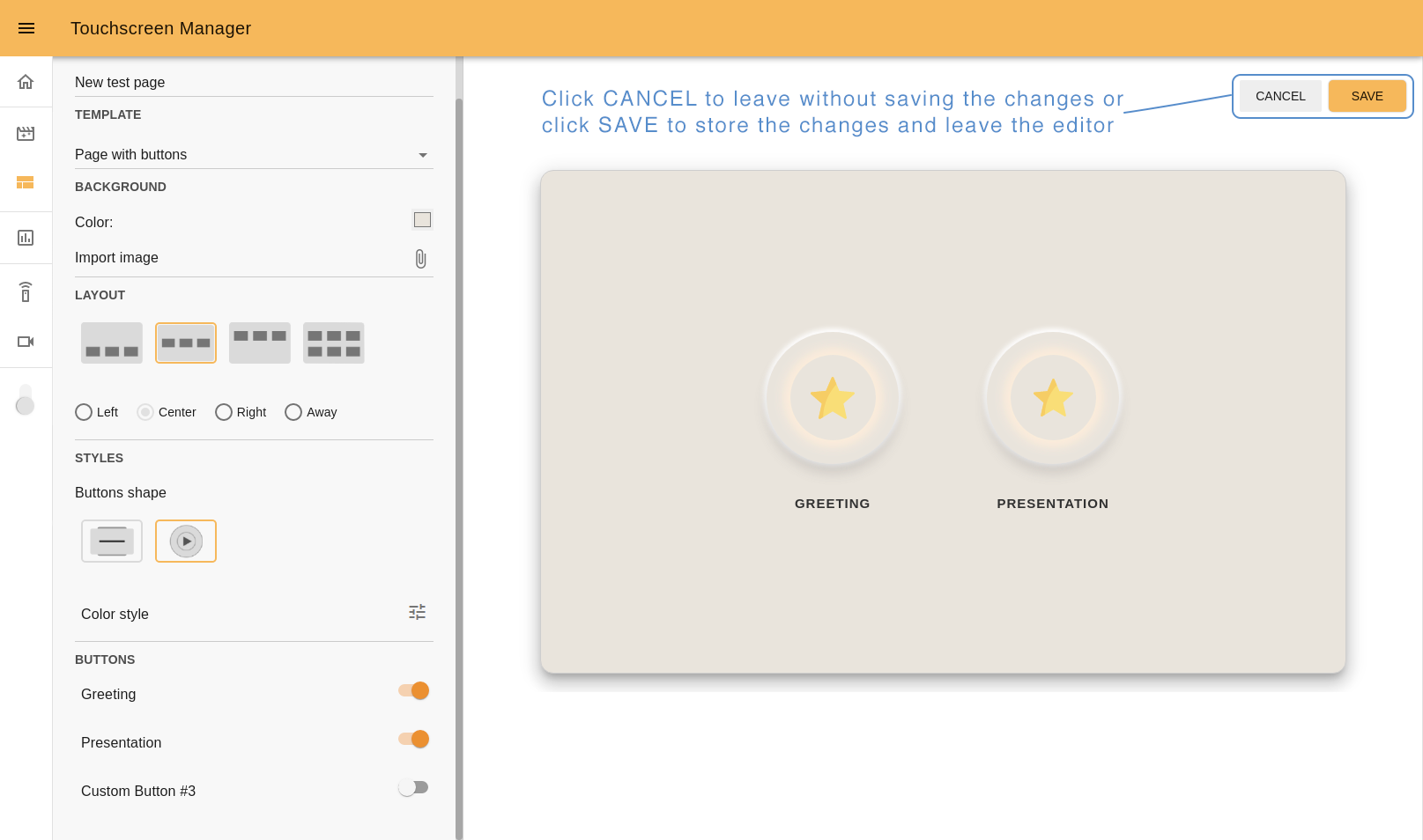
10.9 Command desks
With this app, you can teleoperate the robot, and prepare it for events or other needs, by creating Command desks with groups of buttons inside them. Then you assign actions that the robot will perform when you click any button.
To create a new command desk click on the “NEW COMMAND DESK” button at the top of the page. Near it, at the left top corner menu, you can choose a Command desk created earlier.
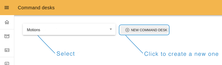
10.9.1 Create a new desk
Type the name of your desk and create a first group (you must have at least one) by clicking on the “plus” icon near the “New group” title. To create a new button, click “ADD NEW”.
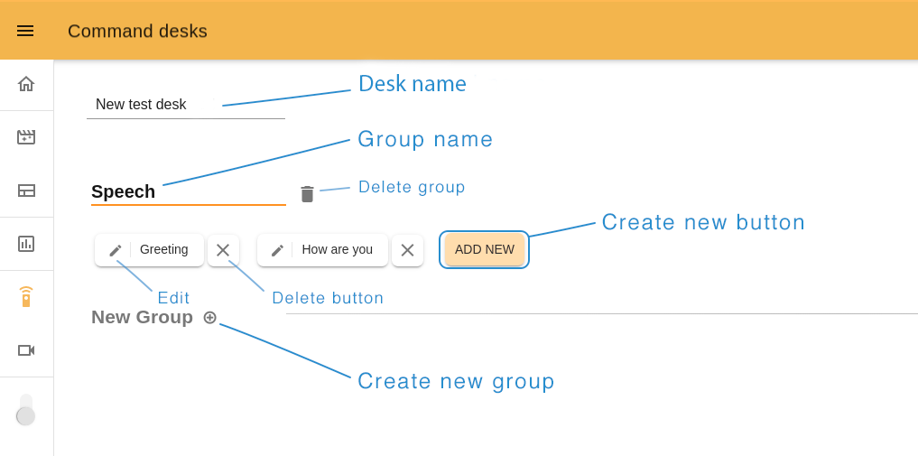
Step 1. Button’s name. Choose a name related to the action this button will perform.
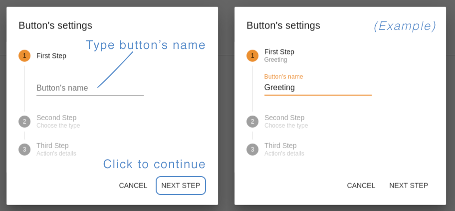
Step 2. Action’s type. You can create buttons with “Motion” type (10.7 Motion Builder), corresponding to the blue circles, so that the robot makes a movement, “Presentation” with a dark brown circle to execute your prerecorded (Presentations) or “Custom Speech type”, which is represented by an orange circle, so that the robot says the written text. In this example we chose “Custom speech”.
The available list of action types depends on the the installed web apps and the robot.
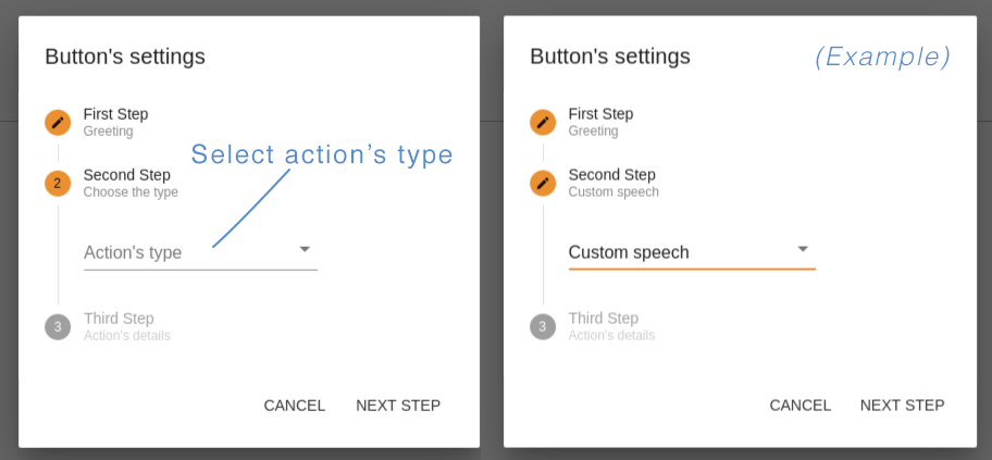
Step 3. Action’s details. Here you should define what ARI will do after clicking on this button. For “Motion” or “Presentation”, choose an option from the list, for “Custom speech” type a custom text for ARI to say, and choose the corresponding language.
The button “TEST NOW” allows you to try your button in action before saving it. If all is ok, click “DONE” to save and close the button editor.
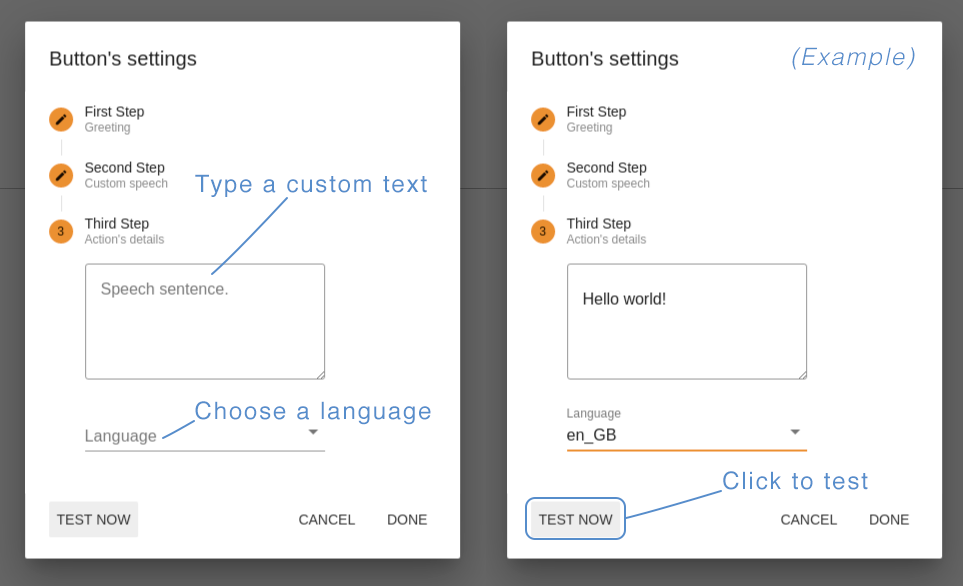
After creating all the buttons you need, click “SAVE” at the right top of the page to exit the Edit mode and return to the Command desk page.
To play the Command press on the the button of the command you would like to execute.
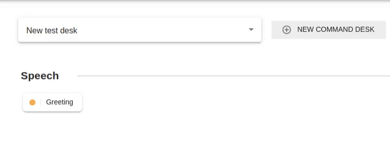
10.9.2 Joystick
With this webapp you can also navigate the robot. The small joystick button at the bottom of the page opens a virtual joystick. Drag the orange circle towards the direction you wish to move the robot.

10.10 Teleoperation
The Teleoperation webapp serves to navigate a robot remotely by using its cameras. The webapp has 2 tabs: teleoperation and exposure tuning.
The Teleoperation tab allows you to see from the head camera’s point of view. With this display you can click anywhere on the image to have ARI look at that point, or, by clicking the navigate icon at the top right and then clicking on an empty spot on the floor, have ARI navigate to this position. The two arrow buttons allow for simple rotation of the base. In this tab you also can Dock/Undock the robot (see 4.2.5 Dock/Undock through WebGUI for further information).
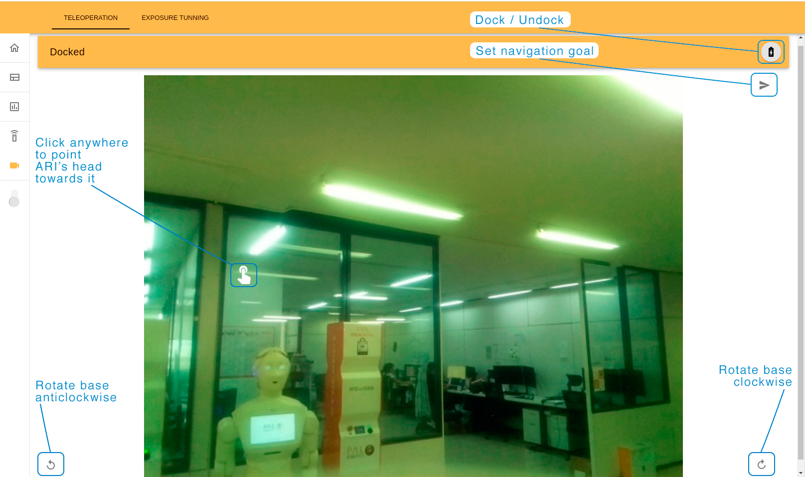
In order to be able to navigate the robot must be in an “Undocked” state, displayed by this text on the top menu, which will also change color to grey.
On the Exposure Tuning tab you can change the exposure settings on the torso front camera, which will affect obstacle avoidance. It is a good practice to do it each time the robot changes its environment. Different quantities of light, and the presence of luminescent light affect the camera image and consequently the robot’s ability to distinguish obstacles on the floor.
To calibrate the exposure, type a number or use the arrow buttons on the bottom of the page to change it. The direction of the arrows (right or left) shows if the exposure number will increase or decrease (respectively). The quantity of the arrows (one or two) means a step of the number changing (10 or 100 respectively). Use the camera image as a reference to a current state of the exposure.
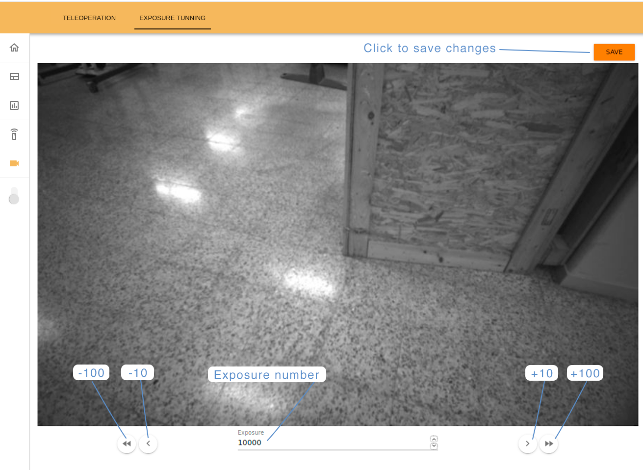
Click on the top-right “SAVE” button to store the current configuration.
11 Mobile base control
The robot base can be teleoperated by using the PAL Teleop functionality through its graphical joystick. The joystick is available both on the Rviz graphical interface or the Web GUI.
Make sure the robot is undocked
Make sure that the robot has sufficient space to move around
The joystick controls both linear and angular velocities at the same time.
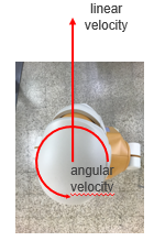
11.1 Moving the base with Rviz Map Editor
Launch the commands listed to launch PAL’s Rviz Map editor with a specific file for navigation. In order to ensure that rviz works properly, make sure that the robot computer is able to resolve the development computer hostname.
export ROS_MASTER_URI=http://ari-0c:1131
export ROS_IP=10.68.0.128
rosrun rviz rviz -d `rospack find ari_2dnav`/config/rviz/navigation.rviz
For more details on the Map Editor and how to use it for navigation, refer to the section ARI’s autonomous navigation system. In order to teleoperate the robot you only need the PAL Teleop and DockUndock panels. Guide the red circle of the graphical joystick towards the direction you wish the robot to move
11.2 Moving the base with WebGUI
You may also access the graphical joystick through the Web GUI, from the Dashboard tab. Open the graphical joystick by pressing the lower-left icon, and drag the orange circle towards the direction you wish to move the robot. Refer to WebGUI chapter for more details.
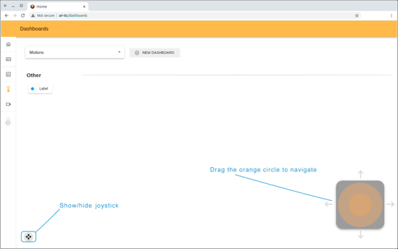
11.3 Mobile base control ROS API
At user level, linear and rotational speeds can be sent to the mobile base controller using the following topic:
/mobile_base_controller/cmd_vel (geometry_msgs/Twist)
These velocities are specified in meters per second and are translated to wheel angular velocities internally.
Different ROS nodes publish velocity commands to the mobile base controller through the /mobile_base_controller/cmd_vel topic. The graphical joystick of Rviz of WebGUI are translated into velocity commands directly through Rviz interface. The move_base node on the other hand is the one in charge of the autonomous navigation, and publishes in a topic the velocity commands required to reach a goal.
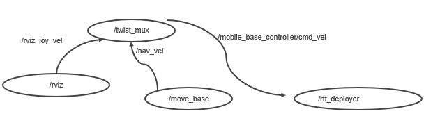
12 Upper body motions
12.1 Overview
This section explains how to move ARI’s two arms, two hands and head, the different ways of controlling each joint and how to execut complex motions.
In total, the controllers that can be moved are:
arm_left_controller: 4 joints
arm_right_controller: 4 joints
hand_left_controller: 1 joint
hand_right_controller: 1 joint
head_controller: 2 joints
Additionally the arm controller provides a safe version, which performs self collision check before executing each trajectory.
12.2 Joint trajectory motions with rqt GUI
The joints can be moved individually using a GUI implemented on the rqt framework. In case of running this example with the real robot, i.e. not in simulation, open the terminal in a development computer and first run:
export ROS_MASTER_URI=http://ari-0c:11311
export ROS_IP=10.68.0.128
Make sure to use your robot’s serial number when exporting the ROS_MASTER_URI variable and to set your development computer’s IP when exportig ROS_IP.
The GUI is launched as follows:
rosrun rqt_joint_trajectory_controller rqt_joint_trajectory_controller
The GUI is shown in figure below. In order to move the arm joint, select /controller_manager in the combo box at the left and the desired controller at the right (e.g. arm_left_controller). Sliders for the four joints of the arm will show up. When using it be careful as self-collisions are not checked and it is possible to move a joint and cause a collision between the arm and the body of the robot.
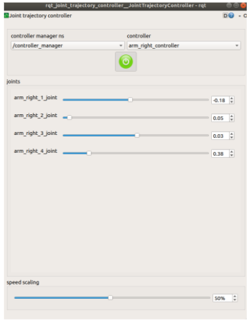
12.3 Joint trajectory motions with Web Commander
The Web Commander offers the option to control the joints of the robot in a similar way, at the Control joints tab. For the arm_left and arm_right the safe joint trajectory topic interfaces are used:
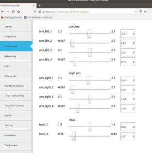
12.4 Joint trajectory motions ROS API
Joint trajectory motions are sent to the joint_trajectory_controller ROS package, an open source ROS package that takes as input joint space trajectories and executes them. Each controller accepts trajectories as ROS messages of type trajectory_msgs/JointTrajectory. Each trajectory point specifies positions, velocities, accelerations or efforts, for all the joint names given and in the same order.
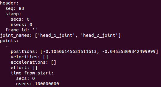
The controllers accepts trajectory goals through their respective ROS topic and action interfaces.
12.5 Predefined upper body motions
While moving individual joints is good for testing, and programming trajectories useful for manipulation tasks, sometimes there are some movements that are always executed the same way, usually for gesturing. For that our robots come with a library of predefined motions. The predefined motions encapsulate trajectories of the robot under a human friendly name, and can be triggered for consistent production of movements. Specifically, it makes use of p**play_motion** ROS package. Saved motions are stored inside ari_bringup/config/ar_motions.yaml and exist in the parameter server.
Example motions include:
bow
look_around
nod
shake_left
shake_right
show_left
show_right
start_ari
wave
Motions can be executed through the WebCommander’s Movements tab or using the rqt action client:
export ROS_IP=10.68.0.128
# For ROS Melodic
rosrun actionlib axclient.py /play_motion

# For ROS Noetic
rosrun actionlib_tools axclient.py /play_motion
In this last case fill the name of the motion in the motion_name field before sending the action goal.
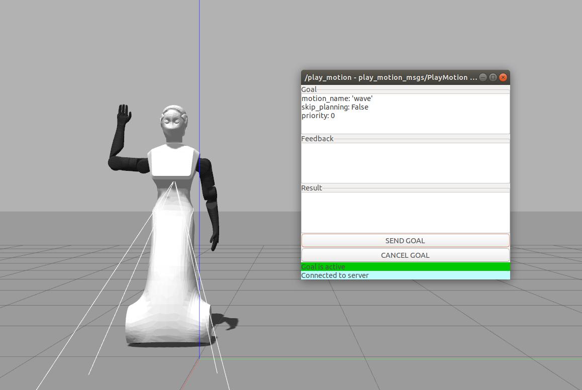
12.5.1 Topic interfaces
/arm_left_controller/command (trajectory_msgs/JointTrajectory)
Sequence of positions that the arm joints have to reach in given time intervals.
/arm_left_controller/safe_command (trajectory_msgs/JointTrajectory)
The same as the previous topic, but the motion is only executed if it does not lead to a self-collision
/arm_right_controller/command (trajectory_msgs/JointTrajectory)
Sequence of positions that the arm joints have to reach in given time intervals.
/arm_right_controller/safe_command (trajectory_msgs/JointTrajectory)
The same as the previous topic, but the motion is only executed if it does not lead to a self-collision
/hand_left_controller/command (trajectory_msgs/JointTrajectory)
Sequence of positions that the hand joints have to reach in given time intervals.
/hand_left_controller/safe_command (trajectory_msgs/JointTrajectory)
The same as the previous topic, but the motion is only executed if it does not lead to a self-collision
/head_controller/command (trajectory_msgs/JointTrajectory)
Sequence of positions that the head joints have to reach in given time intervals.
12.5.2 Action interfaces
/arm_left_controller/follow_joint_trajectory (control_Msgs/FollowJointTrajectory Action)
This action encapsulates the trajectory_msgs/JointTrajectory message.
/safe_arm_left_controller/follow_joint_trajectory (control_msgs/FollowJointTrajectory Action)
The same as the previous topic, but the goal is discarded if a self-collision will occur.
/arm_right_controller/follow_joint_trajectory (control_Msgs/FollowJointTrajectory Action)
This action encapsulates the trajectory_msgs/JointTrajectory message.
/safe_arm_right_left_controller/follow_joint_trajectory (control_msgs/FollowJointTrajectory Action)
The same as the previous topic, but the goal is discarded if a self-collision will occur.
/hand_left_controller/follow_joint_trajectory (control_Msgs/FollowJointTrajectory Action)
This action encapsulates the trajectory_msgs/JointTrajectory message.
/safe_hand_left_controller/follow_joint_trajectory (control_msgs/FollowJointTrajectory Action)
The same as the previous topic, but the goal is discarded if a self-collision will occur.
/head_controller/follow_joint_trajectory (control_Msgs/FollowJointTrajectory Action)
This action encapsulates the trajectory_msgs/JointTrajectory message.
13 Text-to-Speech
ARI incorporates the Acapela Text-to-Speech from Acapela Group
The system is able to generate speech output, based on an input text utterance, by doing the phonetic transcription of the text, predicting the appropriate prosody for the utterance and finally generating the signal waveform.
There are several ways to send text to the TTS engine: using the ROS API, by executing ROS commands in the command line or by implementing a client. Each of them is descibed below.
13.1 Text-to-Speech node
13.1.1 Launching the node
To be able to generate speeches, the soundServer should be running correctly.
System diagnostics allow to check the status of the TTS service running in the robot. These services are started by default on start-up, so normally there is no need to start them manually. To start/stop them, the following commands can be executed in a terminal opened in the multimedia computer of the robot:
pal-start sound_server
pal-stop sound_server
13.1.2 Action interface
The TTS engine can be accessed via a ROS action server named /tts. The full definition and explanation of the action is located in /opt/pal/ferrum/share/pal_interaction_msgs/action/Tts.action, below is a summary of the API:
Goal definition fields:
I18nText text
TtsText rawtext
string speakerName
float64 wait_before_speaking
Result definition fields:
string text
string msg
Feedback message:
In spoken language analysis an utterance is a smallest unit of speech. It is a continuous piece of speech beginning and ending with a clear pause.
uint16 event_type
time timestamp
string text_said
string next_wor
string viseme_id
TtsMark marks
Text to speech goals need to have either the rawtext or the text fields defined, as specified in the sections below.
The field wait_before_speaking can be used to specify a certain amount of time (in seconds) the system has to wait before speaking aloud the text specified. It may be used to generate delayed synthesis.
Sending a raw text goal
The rawtext field of type TtsText has the following format:
string text
string lang_id
The rawtext field needs to be filled with the text utterance ARI has to pronounce and the text’s language should to be specified in the lang_id field. The language Id must follow the format language_country specified in the RFC 3066 document (i.e., en_GB, es_ES, … ).
Sending a I18nText goal
The text field of type I18nText has the following format:
string section
string key
string lang_id
I18nArgument[] arguments
I18n stands for Internationalization, this is used to send a pair of sections and a key that identifies a sentence or a piece of text stored inside the robot.
In this case the lang_id and arguments fields are optional. This allows the user to send a sentence without the need of specifying which language must be used, the robot will pick the language it’s currently speaking and say the sentence in that language.
In the ROS manual you can find examples about how to create an action client that uses these message definitions to generate a speech in ARI .
13.2 Examples of usage
13.2.1 WebCommander
Sentences can be synthesized using the WebCommander, a text field is provided so that text can be written and then synthesized by pressing the Say button.
Additionally buttons can be programmed to say predefined sentences.
Several buttons corresponding to different predefined sentences are provided in the lower part of the Demos tab.
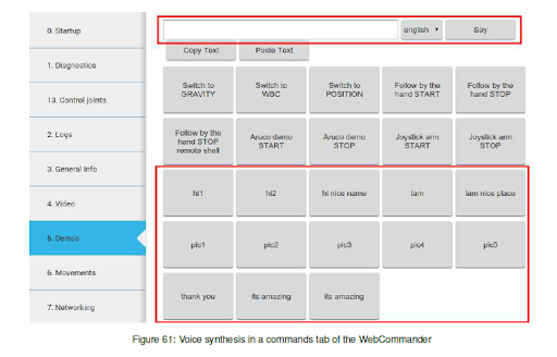
13.2.2 Command line
Goals to the action server can be sent through command line by typing:
rostopic pub /tts/goal pal_interaction_msgs/TtsActionGoal
Then, by pressing Tab, the required message type will be auto-completed. The fields under rawtext can be edited to synthesize the desired sentence, as in the following example:
rostopic pub /tts/goal pal_interaction_msgs/TtsActionGoal "header:
    seq: 0
    stamp:
        secs: 0
        nsecs: 0
        frame_id: ''
    goal_id:
        stamp:
            secs: 0
            nsecs: 0
        id: ''
    goal:
        text:
            rawtext:
                text: 'Hello world'
                lang_id: 'en_GB
            speakerName: ''
    wait_before_speaking: 0.0"
Action client
A GUI included in the actionlib package of ROS Melodic or actionlib_tools in ROS Noetic can be used to send goals to the voice synthesis server.
In order to be able to execute the action successfully, the ROS_IP environment variable should be exported with the IP direction of your development computer:
export ROS_IP=DEV_PC_IP
The GUI can be run as follows:
export ROS_MASTER_URI=http://ARI-0c:11311
# For ROS Melodic
rosrun actionlib axclient.py /tts
# For ROS Noetic
rosrun actionlib_tools axclient.py /tts
Editing the fields inside rawtext parameter and pressing the SEND GOAL button will trigger the action.
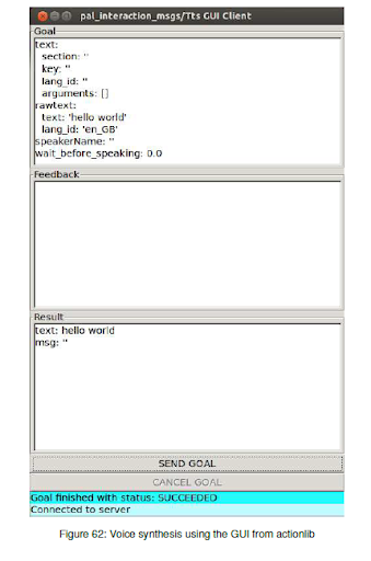
14 Facial perception
This chapter presents the software package for face and emotion recognition included in ARI.
Face and emotion recognition are implemented on top of the Verilook Face SDK provided by Neurotechnolgy.
The ROS package implementing facial perception subscribes to /head_front_camera/image_raw image and processes this topic at 3 Hz in order to provide the following information:
Multiple face detection
3D position estimation
Gender classification with confidence estimation
Face recognition with matching confidence
Facial attributes: eye position and expression
Emotion confidences for six basic emotions
14.1 Facial perception ROS API
Topic interfaces
/pal_face/faces (pal_detection_msgs/FaceDetections)
Array of face data found in the last processed image
/pal_face/debug (sensor_msgs/Image)
Last processed image with overlayed face data: face ROIs, gender, facial features, name and emotion.
In order to visualize the debug image, enter the following command from a development computer:
export ROS_MASTER_URI=http://ari-0c:11311
rosrun image_view image_view image:=/pal_face/debug _image_transport:=compressed
This software is included in the Facial Perception Premium Software package.
14.2 Face perception guidelines
In order to improve the performance of facial perception and to ensure its correct behavior, some basic guidelines have to be taken into account:
Do not have the robot looking at the backlight, i.e. out of a window or towards an indoor lamp. The brightness of the light source will cause high contrast in the images, so that faces may be too dark to be detected.
Best performance is achieved when the subjects are enrolled and recognized at a distance of between 0.5 and 1.2 m from the camera. The further away the person, the worse recognition confidences will be obtained.
When enrolling a new person in a database, it is mandatory that no other faces appear in the image. Otherwise, the stored face data will contain features of both people and the recognition will fail.
In order to reduce the CPU load, the face recognizer should be disabled when possible.
15 Speech Recognition
This chapter presents the software package for online speech recognition included in ARI.
When enabled, the ROS package that implements speech recognition captures audio from the robot’s microphones and sends it to the recognizers for processing. It returns recognized speech.
It has the following features:
Continuous speech recognition.
Recognition after hearing a special keyword.
Ability to use multiple speech recognizers.
Current recognizers implemented:
Google Cloud Speech, available in up to 80 languages
15.1 Requirements
Speech Recognition Premium Software Package.
An appropriate level of ambient noise. The noisier the environment, the worse the recognition results will be.
Google Cloud Speech requirements:
ARI must be connected to the internet and able to reach Google’s servers.
A valid Google Cloud Speech account.
When creating the Google account, ensure to copy the credentials file inside ARI, by doing:
scp google_cloud_credentials.json pal@ari-Xc:/home/pal/.pal/gcloud_credentials.json
15.2 Running speech recognition
Install the speech_multi_recognizer package on both your host PC and inside ARI if it is not installed already. Check the ReSpeaker microphone array’s device id, which is used to capture audio data, by doing the following:
arecord --list-devices
This will indicate the device id of the microphone, for instance, in the following case it will be 1.
card 1: ArrayUAC10 [ReSpeaker 4 Mic Array (UAC1.0)]
Running the following launch file will activate the speech recognition server.
roslaunch speech_multi_recognizer multi_speech_recognition.launch device:=1,0
Then on a separate terminal you can open the action client.
# For ROS Melodic
rosrun actionlib axclient.py /speech_multi_recognizer
# For ROS Noetic
rosrun actionlib_tools axclient.py /speech_multi_recognizer
The language can be set as part of the goal message, if none is specified it will be set as American English. Once the goal is sent, it will listen to input sentences, and deliver a result message. This includes a list of strings with the recognition.
15.3 Speech Recognition ROS API
Action interface
/speech_multi_recognizer (TYPE OF MSGS)
This action starts the speech recognition.
The goal message includes the following data:
language: A BCP47 language tag. For instance en-US.
The feedback message includes the following data:
recognition_results: A list of strings with the recognition, if any. If multiple recognizer engines are configured, it will contain one entry per recognizer that performed a successful recognition.
There is no result message - the action ends when the user aborts. While active, it will perform continuous speech recognition.
Google Cloud Speech account creation
At the time this manual was written, Google offers 60 minutes of online speech recognition per mnth, free of charge. After that, your account will be billed according to your use of their recognition engine. For more information, refer to https://cloud.google.com/speech/pal_interaction_msgs
Go to https://cloud.google.com/speech/ .
Click on “Try it free” .
Log in and agree to the terms and conditions.
Complete your personal/company information and add a payment method
You will be presented with your Dashboard. If not click, here (https://console.cloud.google.com/home/dashboard).
Enter “Speech API” in the search bar in the middle of the screen and click on it.
Click on Enable to enable the Google Cloud Speech API.
Go to the Credentials page (https://console.cloud.google.com/apis/credentials) .
Click on “Create credentials,” and on the dropdown menu select: “Service account key”.
You’ll be asked to create a service account. Fill in the required info and set Role to Project -> Owner.
A .json file will be downloaded to your computer. STORE THIS FILE SECURELY: IT IS THE ONLY COPY.
Copy this file to TIAGo’s /home/pal/.pal/gcloud_credentials.json Google will now use these credentials.
16 Software recovery
16.1 Main robot computer
This section explains the System and Software reinstall procedure for ARI.
Operating system layer
As can be seen, there are two main software blocks: the operating system, which is Ubuntu with the real-time kernel patch Xenomai, and the robotics middleware, which is based on Orocos for real-time, safe communication between processes.
ROS layer
ROS is the standard robotics middleware used in ARI. The comprehensive list of ROS packages used in the robot are classified into three categories:
Packages belonging to the official ROS distribution melodic.
Packages specifically developed by PAL Robotics, which are included in the company’s own distribution, called ferrum.
Packages developed by the customer.
The three categories of packages are installed in different locations of the SSD.
ROS melodic packages and PAL ferrum packages are installed in a read-only partition.
Note that even if these software packages can be modified or removed, at the customer’s own risk, a better strategy is to overlay them using the deployment tool. The same deployment tool can be used to install ROS packages in the user space.
Software startup process
When the robot boots up, the software required for its operation starts automatically. The startup process can be monitored in the WebCommander.
Deploying software on the robot
The deploy tool can be used to:
Install new software onto the robot
Modify the behaviour of existing software packages by installing a newer version and leaving the original installation untouched.
16.1.1 Robot computer installation
The installation is performed using the Software USB drive provided with ARI.
Insert the Software USB drive.
Turn on the robot and press F2 repeatedly. Wait until the BIOS menu appears.
Enter the Boot Menu by pressing F8 and select the Software USB drive.
The Language menu will pop up. Select English.
Select Install ARI.
Select the keyboard layout by following the instructions.
16.2 Head computer installation/update
16.2.1 Installation of head computer
The installation procedure on flashing the Raspberry PI will be updated in future.
16.2.2 Update of head computer
Whenever the robot is connected to the internet, the Raspberry PI automatically pulls the new changes from the servers, before starting its applications.
16.3 NVIDIA TX2 PC installation/update
16.3.1 Installation of NVIDIA TX2 PC
The installation procedure on flashing the Jetson TX2 will be updated in future.
16.3.2 Update of NVIDIA TX2 PC
Whenever the robot is connected to the internet, the Jetson automatically pulls the new changes from the servers, before starting its applications.
17 ROS
17.1 Introduction to modifying robot startup
ARI startup is configured via YAML files that are loaded as ROS Parameters upon robot startup.
There are two types of files: configuration files that describe how to start an application and files that determine which applications must be started for each computer in a robot.
All these files are in the pal_startup_base package within the config directory.
Application start configuration files
These files are placed inside the apps directory within config.
foo_bar.yaml contains a YAML description on how to start the application foo_bar.
roslaunch: "foo_bar_pkg foo_bar_node.launch"
dependencies: ["Functionality: Foo", "Functionality: Bar"]
timeout: 20
The required attributes are:
One of roslaunch, rosrun or bash: used to determine how to start the application. The value of roslaunch,rosrun or bash is the rest of the commands that you would use in a terminal (you can use bash magic inside such as ‘rospack find my_cfg_dir‘). There are also some keywords that are replaced by the robot’s information in order to make scripts more usable. @robot@ is replaced by the robot name as used in our ROS packages (ie REEMH3 is reem, REEM-C is reemc, …)
dependencies: a list of dependencies that need to be running without error before starting this application. Dependencies can be seen in the diagnostics tab on page 68. If an application has no dependencies, it should be set to an empty list [].
Optional attributes:
timeout: applications whose dependencies are not satisfied after 10 seconds are reported as an error.
This timeout can be changed with the timeout parameter.
auto_start: Determines whether this application must be launched as soon as its dependencies are satisfied, if not specified defaults to True.
Examples:
localization.yaml
roslaunch: "@robot@_2dnav localization_amcl.launch"
dependencies: ["Functionality: Mapper", "Functionality: Odometry"]
web_commander.yaml
rosrun: “pal_webcommander web_commander.sh”
dependencies: []
Additional startup groups
Besides the control group, and the multimedia group for robots that have more than one computer, additional directories can be created in the config directory at the same level as the control directory.
These additional groups are typically used to group different applications in a separate tab in the WebCommander, such as the Startup Extras optional tab.
A startup_manager pal_startup_node.py instance is required to handle each startup group.
For instance if a group called grasping_demo is needed to manage the nodes of a grasping demo started in the control computer, a directory will have to be created called grasping_demo containing at least one computer start list yaml file as described in the previous section.
Additionally it is recommended that we add to the control´s computer startup list a new application that will start the startup manager of the grasping_demo so it is available from the start.
rosrun: "pal_startup_manager pal_startup_node.py grasping_demo" dependencies: []
Startup ROS API
Each startup node can be individually controlled using a ROS api that consists of the following services, where {startup_id} must be substituted for the name of the corresponding startup group (ie control, multimedia or grasping_demo).
/pal_startup_{startup_id}/start Arguments are app (name of the application as written YAML files for the application start configuration files) and args (optional command line arguments). Returns a string containing if the app was started successfully.
/pal_startup_{startup_id}/stop Arguments are app (name of the application as written YAML files for the application start configuration files). Returns a string containing if the app was stopped successfully.
/pal_startup_{startup_id}/get_log Arguments are app (name of the application as written YAML files for the application start configuration files) and nlines (number of lines of the log file to return). Returns up to the last lines of logs generated by the specified app.
/pal_startup_{startup_id}/get_log_file Arguments are app (name of the application as written YAML files for the application start configuration files). Returns the path of the log file of the specified app.
Startup command line tools
pal-start
This command will start an application in the background of the computer it is executed on, if it is stopped. Pressing TAB will list the applications that can be started.
pal-stop
This command will stop an application launched via pal_startup in the computer it is executed on, if it is started. Pressing TAB will list the applications that can be stopped.
pal-log
This command will print the name and path of the log file of the selected application. Pressing TAB will list the applications whose log can be seen.
17.2 ROS workspaces
The startup system will look for packages in the following directories in order, if a package is found in one of the directories, it will not be looked for any further on directories lower in the list.
/home/pal/deployed_ws (see 13)
/opt/pal/ferrum
/opt/ros/melodic
Modifying the robot’s startup
In order to enable the robot’s users to fully customize the startup of the robot, in addition to using the files located in the config directory of the pal_startup_base package, the startup procedure will also load all the parameters within /home/pal/.pal/pal_startup/ of the robot’s control computer, if it exists.
To modify the robot’s startup, this directory must be created and have the same structure as the config directory within the pal_startup_base package.
Adding a new application for automatic startup
To add a new application, “new_app”, to the startup, create a new_app.yaml file within the apps directory. Fill it with the information described in Application start configuration files.
The file we created specifies how to start the application, in order to launch the application in the control computer, create a control directory and place it inside a new yaml file, which must consist of a list containing
new_app.
For instance:
/home/pal/.pal/pal_startup/apps/new_app.yaml
roslaunch: "new_app_package new_app.launch"
dependencies: []
/home/pal/.pal/pal_startup/control/new_app_list.yaml
- new_app
Modifying how an application is launched
To modify how the application “foo_bar” is launched, copy the contents from the original foo_bar.yaml file in the pal_startup_base package and perform the desired modifications.
Adding a new workspace
In cases where the workspace resolution process needs to be changed, the file at /usr/bin/init_pal_env.sh can be modified to adapt the environment of the startup process.
17.3 Deploying software on the robot
When ARI boots up it always adds two sources of packages to its ROS environment. One is the ROS software distribution of PAL Robotics at /opt/pal/ferrum/, the other is a fixed location at /home/pal/deployed_ws, which is where the deploy tool installs to. This location precedes the rest of the software installation, making it possible to overlay previously installed packages.
To maintain consistency with the ROS release pipeline, the deploy tool uses the install rules in the CMake-Lists.txt of every catkin package. Make sure that everything you need on the robot is declared to be installed.
Usage
usage: deploy.py [-h] [--user USER] [--yes] [--package PKG]
[--install_prefix INSTALL_PREFIX]
[--cmake_args CMAKE_ARGS]
robot
Deploy built packages to a robot. The default behavior is to deploy *all*
packages from any found workspace. Use --package to only deploy a single package.
positional arguments: robot
hostname to deploy to (e.g. ari-0c)
optional arguments:
-h, --help show this help message and exit
--user USER, -u USER username (default: pal)
--yes, -y don't ask for confirmation, do it
--package PKG, -p PKG deploy a single package
--install_prefix INSTALL_PREFIX, -i INSTALL_PREFIX
Directory to deploy files
--cmake_args CMAKE_ARGS, -c CMAKE_ARGS
Extra cmake args like
--cmake_args="-DCMAKE_BUILD_TYPE=Release"
e.g.: deploy.py ari-0c -u root -p pal_tts -c="-DCMSAKE_BUILD_TYPE=Release"
Notes
The build type by default is not defined, meaning that the compiler will use the default C++ flags. This is likely to include -O2 optimization and -g debug information, meaning that, in this mode, executables and libraries will go through optimization during compilation and will therefore have no debugging symbols.
This behaviour can be changed by manually specifying a different option such as:
–cmake_args=”-DCMAKE_BUILD_TYPE=Debug”
–cmake_args=”-DCMAKE_BUILD_TYPE=Debug -DPCL_ONNURBS=1”
If an existing library is overlaid, executables and other libraries which depend on this library may break.
This is caused by ABI / API incompatibility between the original and the overlaying library versions. To avoid this, is it recommended to simultaneously deploy the packages that depend on the changed library.
There is no tool to remove individual packages from the deployed workspace except to delete the /home/pal/deployed_ws folder altogether.
Deploy tips
You can use an alias ( you may want to add it to your .bashrc) to ease the deploy process:
alias deploy="rosrun pal_deploy deploy.py"
You can omit the –user pal as it is the default argument
You may deploy a single specific package instead of the entire workspace:
deploy -p hello_world ARI-0c
You can deploy multiple specific packages instead of the entire workspace:
deploy -p "hello_world other_local_package more_packages" ARI-0c
Before deploying you may want to do a backup of your previous ~/deployed_ws in the robot to be able to return to your previous state, if required.
Use-case example
Adding a new ROS Package
In the development computer, load the ROS environment (you may add the following instruction to the ~.bashrc)
source /opt/pal/ferrum/setup.bash
Create a workspace
mkdir -p ~/example_ws/src
cd ~/example_ws/src
Create a catkin package
catkin_create_pkg hello_world roscpp
Edit the CMakeLists.txt file with the contents
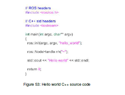
Build the workspace
cd ~/example_ws
catkin build
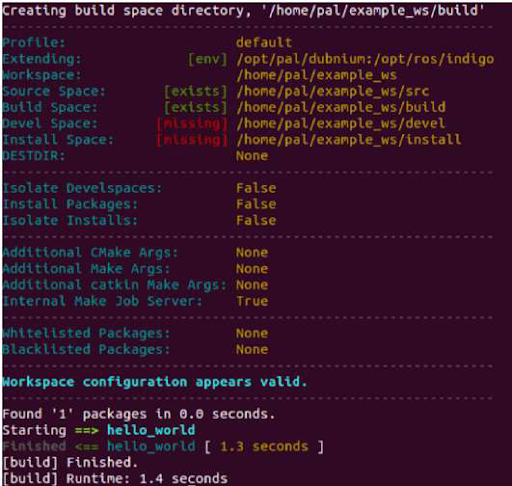
Deploy the package to the robot:
cd ~/example_ws
rosrun pal_deploy deploy.py --user pal ARI-0c
The deploy tool will build the entire workspace in a separate path and, if successful, it will request confirmation in order to install the package on the robot.
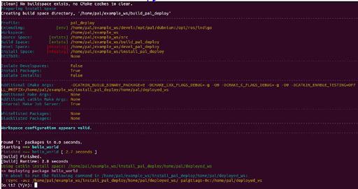
Press Y so that the package files are installed on the robot computer.
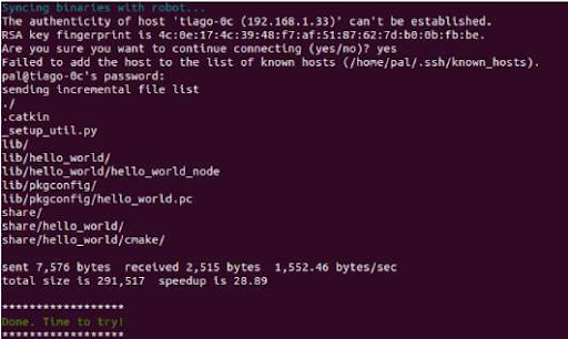
for the hello world package, according to the installation rules specified by the user in the CMakeLists.txt.
Then connect to the robot:
ssh pal@ARI-0c
And run the new node as follows:
rosrun hello_world hello_world_node
If everything goes well you should see ’Hello world’ printed on the screen.
Adding a new controller
One use-case for the tool is to add or modify controllers. Let’s take the ros_controllers_tutorials package, as it contains simple controllers, to demonstrate the power of deploying.
First, list the known controller types on the robot. Open a new terminal and execute the following:
export ROS_MASTER_URI=http://ARI-0c:11311
rosservice call /controller_manager/list_controller_types | grep HelloController
As it is a genuine installation, the result should be empty.
Assuming a running robot and a workspace on the development computer called ARI_ws that contains the sources of ros_controllers_tutorials, open a new terminal and execute the following commands:
cd ARI_ws
catkin_make #-j5 #optional
source devel/setup.bash # to get this workspace into the development environment
rosrun pal_deploy deploy.py --package ros_controllers_tutorials ARI-0c
The script will wait for confirmation before copying the package to the robot.
Once successfully copied, restart the robot and run the following commands again:
export ROS_MASTER_URI=http://ARI-0c:11311
rosservice call /controller_manager/list_controller_types | grep HelloController
Now, a list of controller types should appear. If terminal highlighting is enabled, “HelloController” will appear in red.
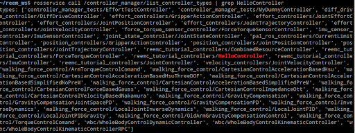
Modifying an installed package
Now let’s suppose we found a bug on an installed controller inside the robot. In this case, we’ll change the joint_state_controller/JointStateController.
Go to https://github.com/ros-controls/ros_controllers, open a new terminal and execute the following commands:
cd ARI_ws/src
git clone https://github.com/ros-controls/ros_controllers
# Fix bugs in controller
cd ..
catkin_make #-j5 #optional
source devel/setup.bash # to get this workspace into the development environment
rosrun pal_deploy deploy.py --package joint_state_controller ARI-0c
After rebooting the robot, the controller with the fixed changes will be loaded instead of the one installed in/opt/
17.4 Software recovery
Development computer installation
Hardware installation Connect the computer to the electric plug, the mouse and the keyboard. Internet access is not required as the installation is self-contained.
Software Installation
The installation is performed using the Software USB drive provided with ARI.
Insert the Software USB drive.
Turn on the computer, access the BIOS and boot the Software USB drive.
The Language menu will pop up. Select English.
Choose Install Development (Advanced) if you wish to select a target partition in the development computer. Using the “Install Development” option will delete all partitions in the disk and automatically install the system in a new partition.
Select the keyboard layout by following the instructions.
Default users
The following users are created by default:
root: Default password is palroot.
pal: Default password is pal.
aptuser: Default password is palaptuser.
17.5 Development computer
The operating system used in the SDE Development Computer is based on the Linux Ubuntu 16.04 LTS distribution. Any documentation related to this specific Linux distribution applies to SDE. This document only points out how the PAL SDE differs from the standard Ubuntu 16.04.
Computer requirements
A computer with 8 CPU cores is recommended. A powerful graphics card with resolution of at least 1920x1080 pixels is recommended in order to have a better user experience when using visualization tools like rviz and the Gazebo simulator. The development computer ISO provides support for Nvidia cards. In case of upgrading the kernel of the development computer PAL Robotics cannot ensure proper support for other graphic cards.
Setting ROS environment
In order to use the ROS commands and packages provided in the development ISO the following command needs to be executed when opening a new console:
source /opt/pal/ferrum/setup.bash
A good way to spare the execution of this command every time is to append it at the /home/pal/.bashrc file.
ROS communication with the robot
When developing applications for robots based on ROS, it is typical to have the rosmater running on the robot’s computer and the development computer running ROS nodes connected to the rosmaster of the robot. This is achieved by setting in each terminal of the development computer running ROS nodes the following environment variable:
export ROS_MASTER_URI=http://ARI-0c:11311
Note that in order to successfully exchange ROS messages between different computers, each of them needs to be able to resolve the hostname of the others. This means that the robot computer needs to be able to resolve the hostname of any development computer and vice versa. Otherwise, ROS messages will not be properly exchanged and unexpected behavior will occur.
Do the following checks before starting to work with a development computer running ROS nodes that point to the rosmaster of the robot:
ping ARI-0c
Make sure that the ping command reaches the robot’s computer.
Then do the same from the robot:
ssh pal@ARI-0c
ping devel_computer_hostname
If ping does not reach the development computer then proceed to add the hostname to the local DNS of the robot. Otherwise, you may export the environmental variable ROS_IP - the IP of the development computer that is visible from the robot. For example, if the robot is set as access point and the development computer is connected to it and it has been given IP 10.68.0.128 (use ifconfig to figure it out), use the following command in all terminals used to communicate with the robot:
export ROS_MASTER_URI=http://ARI-0c:11311
export ROS_IP=10.68.0.128
All ROS commands sent will then use the computer’s IP rather than the hostname.
Compiling software
The development computer includes the ROS messages, system headers and our C++ open source headers necessary to compile and deploy software to the robot. Some of the software APIs that we have developed are proprietary, and their headers are not included by default. If you require them you can contact us through our customer service portal and after signing a non disclosure agreement, they will be provided. These APIs are for accessing advanced features not available through a ROS API.
System Upgrade
In order to upgrade the software of the development computers, you have to use the pal_upgrade_chroot.sh command. Log in as root and execute:
root@development:~# /opt/pal/ferrum/lib/pal_debian_utils/pal_upgrade_chroot.sh
Notifications will appear whenever software upgrades are available.
17.6 ARI’s internal computers
ARI LAN The name of ARI ’s computer is ARI-0c, where 0 needs to be replaced by the serial number of your robot. For the sake of clarity, hereafter we will use ARI-0c to refer to ARI’s computer name.
In order to connect ot the robot, use ssh as follows:
ssh pal@ARI-0c
Users
The users and default passwords in the ARI computers are:
root: Default password is palroot.
pal: Default password is pal.
aptuser: Default password is palaptuser.
File system
File system The ARI robot’s computer has a protection against power failures that could corrupt the filesystem. These partitions are created:
/ : This is an union partition, the disk is mounted in /ro directory as read-only and all the changes are stored in RAM. So, all the changes are not persistent between reboots.
/home : This partition is read-write. Changes are persistent between reboots.
/var/log : This partition is read-write. Changes are persistent between reboots.
In order to work with the filesystem as read-write do the following:
root@ARI-0c:~# rw
Remounting as rw...
Mounting /ro as read-write
Binding system files... root@ARI-0c:~# chroot /ro`
rwcommand remounts all the partitions as read-write. Then with a chroot to /ro we have the same system than the default but all writable. All the changes performed will be persistent.
In order to return to the previous state do the following:
root@ARI-0c:~# exit
root@ARI-0c:~# ro
Remount /ro as read only
Unbinding system files
First exit command returns from the chroot. Then the ro script remounts the partitions in the default way.
Internal DNS
The control computer has a DNS server that is used for the internal LAN of the ARI with the domain name reem-lan. This DNS server is used by all the computers connected to the LAN.
When a computer is added to the internal LAN (using the Ethernet connector, for example) it can be added to the internal DNS with the command addLocalDns:
root@ARI-0c:~# addLocalDns -h
-h shows this help
-u DNSNAME dns name to add
-i IP ip address for this name Example: addLocalDns -u terminal -i 10.68.0.220.
The same command can be used to modify the IP of a name: if the dnsname exists in the local DNS, the IP address is updated.
To remove names in the local DNS, exit the command delLocalDns:
root@ARI-0c:~# delLocalDns -h
-h shows this help
-u DNSNAME dns name to remove
Example: addLocalDns -u terminal
These additions and removals in the local DNS are not persistent between reboots.
NTP
Since big jumps in the local time can have undesired effects on the robot applications, NTP is setup when the robot starts and before the ROS master is initiated. If no synchronization was possible, for example if the NTP servers are offline, the NTP daemon is stopped after a timeout.
To setup ntp as a client edit the /etc/ntp.conf file and add your desired ntp servers. You can use your own local time servers or external ones, such as ntp.ubuntu.com. You can also try uncommenting the default servers already present. For example, if the local time server is in 192.168.1.6 add the following to the configuration file.
server 192.168.1.6 iburst
Restart the ntp daemon to test your servers.
systemctl restart ntp.service
Run the ntpq -p command and check that at least one of the configured servers has a nonzero reach value and a nonzero offset value. The corrected date can be consulted with the date command. Once the desired configuration is working make sure to make the changes in /etc/ntp.conf persistent and reboot the robot.
If, on the contrary, you want the robot to act as the NTP server of your network, no changes are needed. The current ntp daemon already acts as a server. You will only need to configure NTP for the clients.
To configure NTP on the rest of the clients, like the development PCs, run:
systemctl status ntp.service
If the service is active follow the previous steps to configure the ntp daemon. Once again a private or public NTP server can be used. If, instead the robot is desired as a server add this line to /etc/ntp.conf.
server ARI-Xc iburst
If the service is not found then that means ntp is not installed. Either install it with apt-get install ntp or make use of Ubuntu’s default ntp client called timesyncd.
To configure timesyncd simply edit the /etc/systemd/timesyncd.conf file and set the proper NTP server.
Restart the timesyncd daemon.
systemctl restart systemd-timesyncd.service
Check the corrected date with the date command. The time update can take a few seconds.
System upgrade
For performing system upgrades connect to the robot, make sure you have Internet access and run the pal_upgrade command as root user. This will install the latest ARI software available from the PAL repositories. Reboot after upgrade is complete.
Firmware update
Check for updates for the pal-ferrumfirmware-* packages and install them.
Before running the script, place the arm in a safe position with a support underneath it, as during the installation of the script, the arm can tumble.
Run the update_firmware.sh script, as shown below. The update will take a few minutes.
pal@ARI-0c:~# rosrun firmware_update_robot update_firmware.sh
Finally, shut it down completely, power off with the electric switch and then power up the robot.
Meltdown and Spectre vulnerabilities
Meltdown and Spectre exploit critical vulnerabilities in modern processors. Fortunately the linux Kernel has been patched to mitigate these vulnerabilities, this mitigation comes at a slight performance cost.
PAL Robotics configuration does not interfere with mitigation, whenever the installed kernel provides mitigation, it is not disable by our software configuration.
Below we provide some guidelines to disable the mitigation in order to recover the lost performance, this is not recommended by PAL Robotics and it is done on the customer’s own risk.
On this website the different tunables for disabling mitigation controls are displayed. These kernel flags must be applied to the GRUB_CMDLINE_LINUX in /etc/default/grub.
After changing them, update-grub must be executed, and the computer must be rebooted. These changes need to be made in the persistent partition.
Be extremely careful when performing these changes, since they can prevent the system from booting properly.
17.7 Introspection controller
The introspection controller is a tool used at PAL Robotics to serialize and publish data on the real robot that could be recorded and used later for debugging.
Start the controller
The introspection controller doesn’t use any resource, and it could be activated in parallel with any other controller.
In order to start it run:
ssh pal@ARI-0c
roslaunch introspection_controller introspection_controller.launch
Once the controller is started it will start publishing all the information on the topic: /introspection_data/full
Record and reproduce the data
If you want to record the information from your experiment, it can simply be done using rosbag.
ssh pal@ARI-0c
rosbag record -O NAME_OF_THE_BAG /introspection_data/full
Once you are finished to record your experiment simply close it with Ctrl-C
Then copy this file in your development PC.
ssh pal@ARI-0c
scp -C NAME_OF_THE_BAG.bag pal@development:PATH_TO_SAVE_IT
Once in your development PC you can reproduce it using PlotJuggler.
rosrun plotjuggler PlotJuggler
Once PlotJuggler is open load the bag: File -> Load Data and select the recorded rosbag.
For more information about PlotJuggler please visit: http://wiki.ros.org/plotjuggler
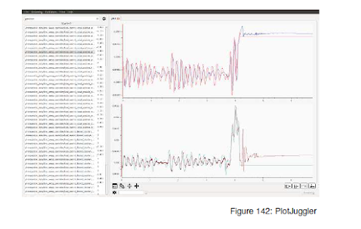
Figure: PlotJuggler
Record new variables
In order to record new variables it will be necessary to register them inside your code as follows.
#include < pal_statistics / pal_statistics .h>
#include < pal_statistics /pal_statistics_macros.h>
#include < pal_statistics / registration_utils .h>
...
double aux = 0;
pal_statistics :: RegistrationsRAII registered_variables_;
REGISTER_VARIABLE("/introspection_data", "example_aux", &aux, ®istered_variables_);
Eigen::Vector3d vec(0,0,0);
REGISTER_VARIABLE("/introspection_data", "example_vec_x", &vec[0], ®istered_variables_);
REGISTER_VARIABLE("/introspection_data", "example_vec_y", &vec[1], ®istered_variables_);
REGISTER_VARIABLE("/introspection_data", "example_vec_z", &vec[2], ®istered_variables_);
...
Take in account that the introspection controller only accepts one dimensional variables. For more information please check: https://github.com/pal-robotics/pal_statistics
18 Customer service
18.1 Support portal
All communication between customers and PAL Robotics is made using tickets in a helpdesk software. This web system can be found at http://support.pal-robotics.com. New accounts will be created on request by PAL Robotics.
Once the customer has entered the system, two tabs can be seen: Solutions and Tickets. The Solution section contains FAQs and News from PAL Robotics . The Tickets section contains the history of all tickets the customer has created.
18.2 Remote support
A technician from PAL Robotics can give remote support. This remote support is disabled by default, so the customer has to activate it manually. Using an issue in the support portal, the PAL Robotics technician will provide the IP address and port the customer has to use.
19 Navigation Appendix
19.1 Appendix A: Managing Maps
When finished mapping, two files will be saved: a map.pgm occupancy grid image file and a map.yaml binary configuration file. These files will be stored in the path
$HOME/.pal/ari_maps/configurations in the robot’s file system. The current map in use is the one
pointed to by the symbolic link $HOME/.pal/ari_maps/config
In order to list all the maps stored in the robot the button Refresh List of the Map Configuration panel must be clicked. The list of available maps will appear in the panel as shown in the figure below. Note that the one shown in bold is the active one.
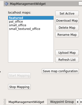
When the navigation is in localization mode, any of the maps stored in $HOME/.pal/ari_maps/configurations can be selected.
Map operations available are:
Set Active: the map selected in the list will be loaded and used for navigation
Download Map: this button saves the selected map in the list in the path of the local computer running the Rviz specified by the user
Delete Map: removes the selected map from the robot
Rename Map: change the name of the selected map
Upload Map: copy a map from the local computer to the robot’s computer.
19.2 Appendix B: Mapping and managing maps through a terminal window
Another option is to use a terminal window for the mapping process, by calling the following service of the pal_map_manager to initiate it:
export ROS_MASTER_URI=http://ari-0c:11311
export ROS_IP=10.68.0.128
rosservice call /pal_navigation_sm "input: 'MAP'"
To save the map just built in the right path automatically, use can use the save_map service:
export ROS_MASTER_URI=http://ari-0c:11311
export ROS_IP=10.68.0.128
rosservice call /pal_map_manager/save_map “directory: ‘’”
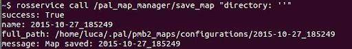
The save_map service will store all the map files in the same path as indicated above.
Once mapping is finished, instead of using Rviz it is possible to call the following service from a terminal window to save the map and start the localization mode in the latest built map:
export ROS_MASTER_URI=http://ari-0c:11311
export ROS_IP=10.68.0.128
rosservice call /pal_navigation_sm "input: 'LOC'"
To select a different map the following command can be used, which corresponds to the “Set Active” button of the MapManagementWidget:
ssh pal@ari-3c
rosservice call /pal_map_manager/change_map "input: 'MAP_NAME'"
where MAP_NAME is the name of the map that we want to select.